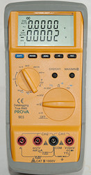
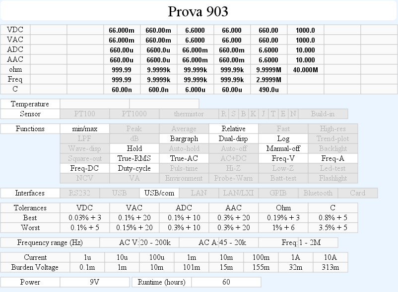
DMM Prova 903
This is a very advanced meter from "TES", it is supposed to be very precise and has two channels (That is two meters in one).
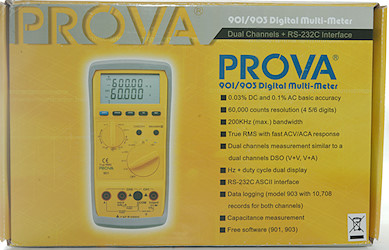
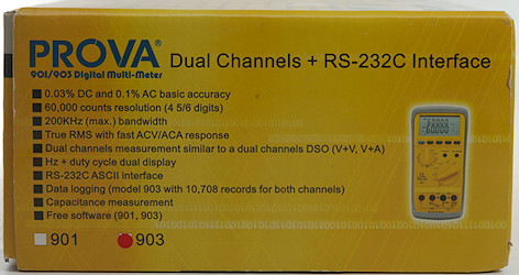

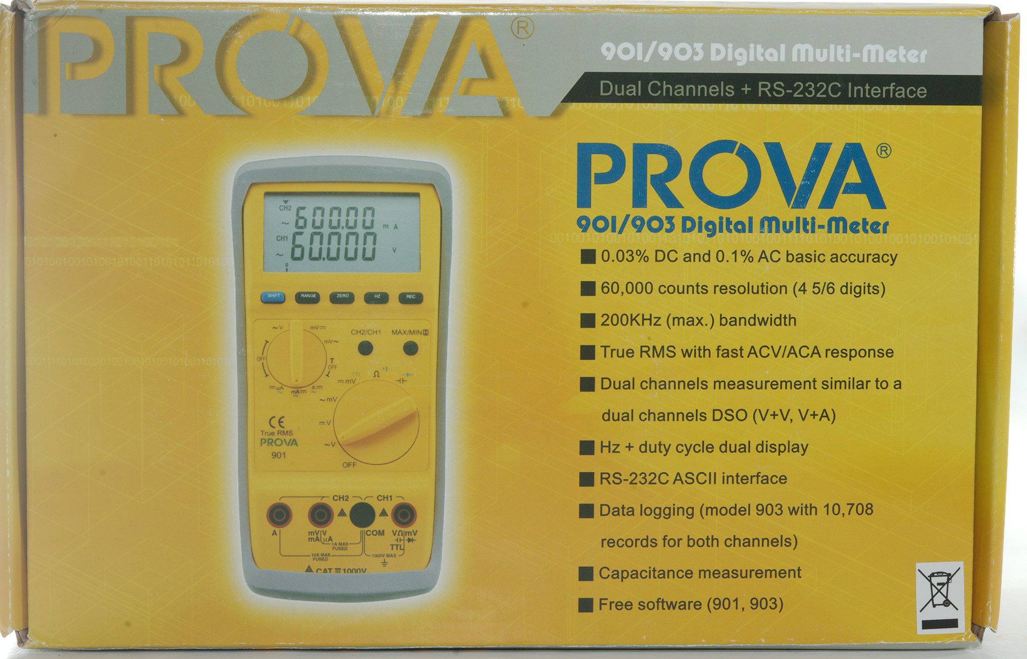
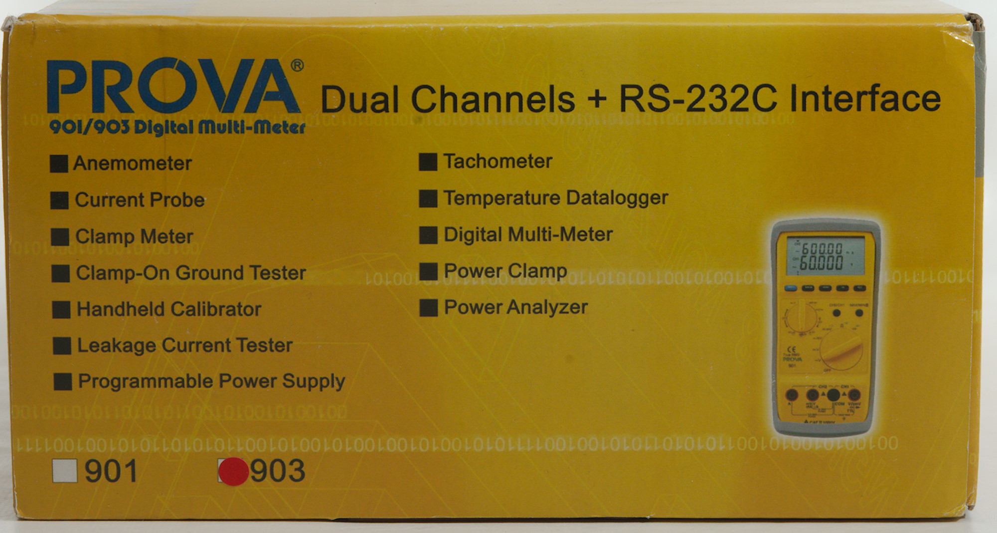
The meter arrived in a cardboard box that is used for the two top models.
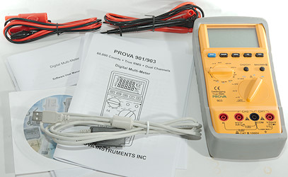
The box included the meter, two probes, two wires with alligator clips, a computer interface, four manuals (English + Chinese for meter and software).
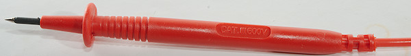
Probes are unbranded and rated for CAT III 600V
The plug is fully shrouded and standard probe plug size.
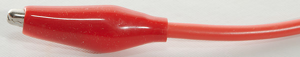
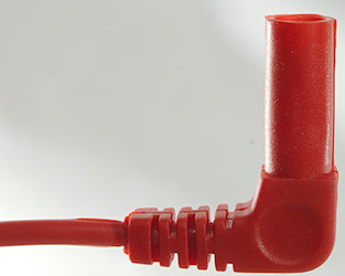
Alligator clips do not have a CAT rating
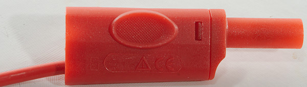
The plugs are stackable shrouded plugs, this makes it possible to share the common input terminal on the meter.
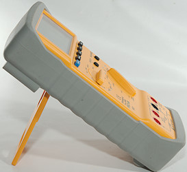
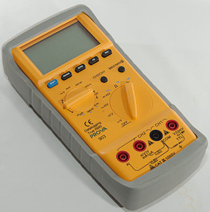
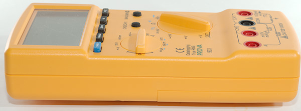
The meter is heavy and the tilting bale can hold it while the range switch is used or the buttons is pressed.
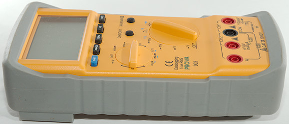
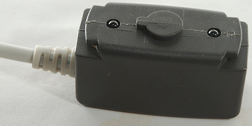
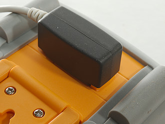
The PC connection is here with an optical link.
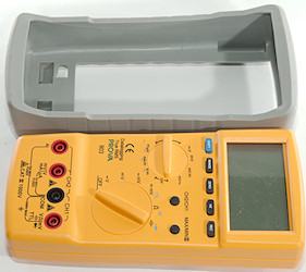
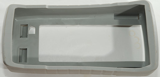
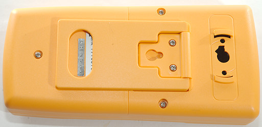
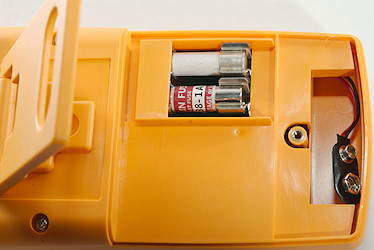
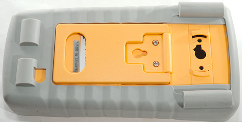
The rubber sleeve must be removed to replace the battery. Both battery and fuse is accessible with one screw removed.
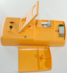
The screw stays in the lid (nice).
Display
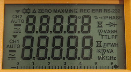
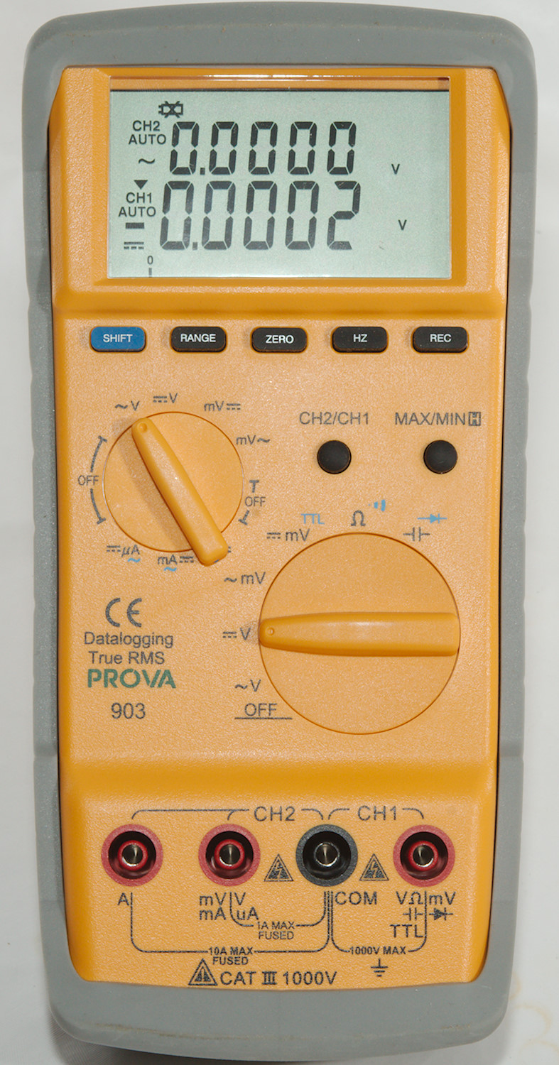
The above picture shows all the segments on the display. The meter use nearly all of them.
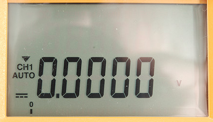
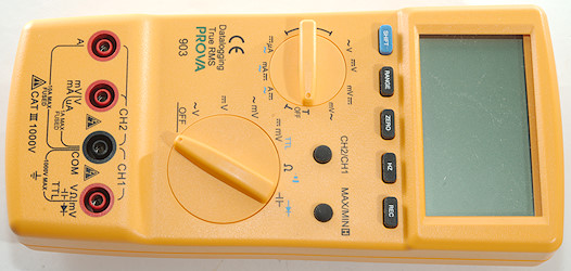
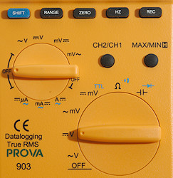
This readout and the bargraph is for the large rotary switch and the V input terminal.
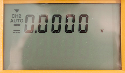
The upper readout is for the small rotary switch and the V/mA input.
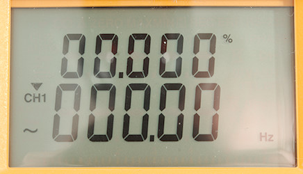
When frequency and duty cycle is selected (Hz button or SHIFT to TTL mode) both displays are used, one for frequency, the other for duty cycle.
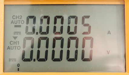
Both range switches used, one on A and one on V. The triangle above CH1 shows what readout the button rows will affect, press CH2/CH1 to change to CH2.
Functions
Buttons (Generally the buttons are rather slow to use):
- Shift (blue): Select the blue modes on the range switches.
- Range: Switch to manual range and select range, hold down to activate automatic ranging again.
- Zero: Zero the value and show relative values, hold down to disable.
- Hz: Switch to frequency and duty cycle mode in volt and current modes, this works for both range switches and for both AC and DC (It will switch to AC internally).
- Rec: Start recording data, meter can only record one type of data and must be cleared before next logging session. Hold down to turn logging off again. If the button is held down during power on the recordings are cleared and it is possible to adjust the sample interval.
- CH2/CH1: Use to select what channel the buttons works on
- Max/min/hold: Freeze the display and starts recording min/max values, pressing the button will change between hold/min/max values (Bargraph will show actual value). Hold down to disable.
Zero, Rec and max/min/hold will all disable auto range.
Small Rotary switch:
- Off: Meter is turned off.
- VAC: Measure AC volt on the mA/V terminal
- VDC: Measure DC volt on the mA/V terminal
- mVDC: Measure mDC volt on the mA/V terminal
- mVAC: Measure mAC volt on the mA/V terminal
- Off: Meter is turned off.
- A: Measure A current on the A terminal, use SHIFT to select AC
- mA: Measure mA current on the mA/V terminal, use SHIFT to select AC
- uA: Measure uA current on the mA/V terminal, use SHIFT to select AC
Large Rotary switch:
- Off: Meter is turned off.
- VAC: Measure AC volt on the V terminal
- VDC: Measure DC volt on the V terminal
- mVAC: Measure mAC volt on the V terminal
- mVDC: Measure mDC volt on the V terminal, this is also the TTL frequency input.
 : Resistance and continuity.
 : Capacitance and diode range.
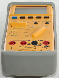
Input
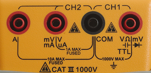
- A: High current, maximum current is 10A.
- mAuAmVV: The lower current ranges and + voltage input for the small rotary switch.
- CON: The common terminal for all ranges and both inputs (Use the stackable alligator clip lead for one input).
- xxx: All ranges on the large rotary switch.
Measurements
- Volt and frequency
- TTL frequency input triggers around 0.8V and requires at least 1Vpp
- AC frequency input requires a zero crossing.
- At 2Vpp square wave input on TTL the frequency range is from 1Hz to 1.5MHz
- At 100mVrms input on mVAC range, frequency range is from 2Hz to 800kHz
- Duty cycle on TTL works from 2% to 99% at 100kHz with 4Vpp, precision is within 1.3 (Precision improves with lower frequency)
- 1 VAC is 5% down at 600kHz (RMS will not work at the frequency).
- Max/min needs about 200ms to capture a voltage.
- Input impedance is 10-11Mohm on VDC
- Input impedance is 5Mohm on mVDC main input up to about 3.6V and high on mVDC secondary input up to about 1.5V.
- AC input has a capacitor, both V and mV
- Rated overload protection on V ranges is 1000VDC/VAC
- Precision is only valid when one input is used, with two inputs it will be lower.
- TTL Frequency input is 5Mohm up to about 3.5V, then it drops to 1Mohm at 8V and 1kOhm at 30V
- Current
- 10A range may be loaded to 20A for 30 seconds
- Overload protection in uA and mA: 1A/1000V 10x38mm fuse
- Overload protection in A: 20A/1000V 10x38mm fuse
- Ohm, continuity, diode and capacitance
- Ohm needs about 1.5s to measure 100ohm
- Ohm is 1.2V open and 1.05mA shorted
- Continuity is very fast (Below 10ms).
- Continuity beeps when resistance is below 50ohm
- Continuity is 3.3V open and 1.05mA shorted
- Diode range uses 3.3V, max. display is 2.0000V at 0.46mA, max. current is 1.05mA shorted
- 400uF takes about 5 seconds to measure.
- Rated overload protection is 1000VAC, no specification for capacitance range.
- Miscellaneous
- Current consumption of meter is 8mA (Secondary display adds about 0.2mA)
- Meter works down to 4.4V where the display is faded, battery symbol show at 6.9V, but only if second channel is on.
- The meter reading will change from 6.0V, a 5V reading shows 6.6V at 4.6V battery voltage
- The meter usual needs two display updates before the reading is fully correct.
- Viewing angle is good
- Display updates around 1.5 times/sec with one reading on and 1 times/sec with dual readings
- Bargraph updates fast
- Will not turn power off automatic
- Standard probes fits perfectly into sockets on meter.
- Weight is 615g without accessories, but with sleeve and batteries.
- Size is 210 x 104 x 55mm.
- Probes
- Probe resistance 54mOhm for one.
- Probe wire is soft and 90cm long.
- Alligator wire resistance 22mOhm for one.
- Alligator wire is soft and 80cm long.
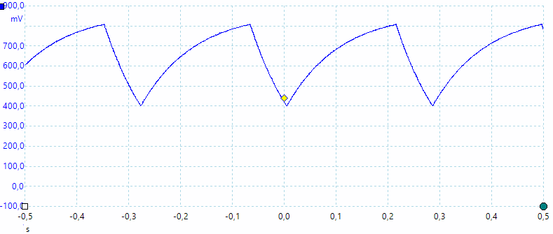
A look at the capacitance measurement waveform.
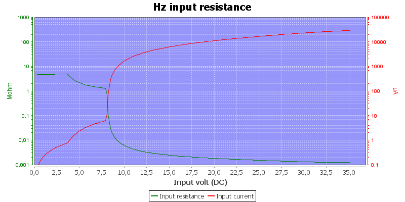
TTL Frequency input impedance.
The high ohm ranges are very sensitive to noise and may jump a bit up/down.
Ohms values just above the maximum range (i.e. 40-60Mohm) makes the display freeze, higher values will show OL
In manual range all capacitor ranges can be used up to 9999, that means highest value is 999.9uF
Tolerances are only valid with one channel on, they are worse when both channels are used.
Software
The software and cable is included.
The cable is an optical connection and uses a usb connector on the PC side. It is a CP2102 chip and a working driver was supplied on the CD. The software installs VISA drivers.

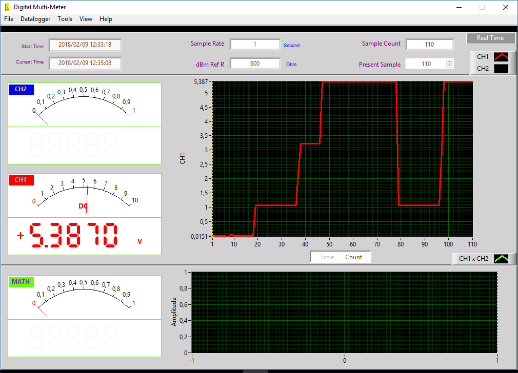
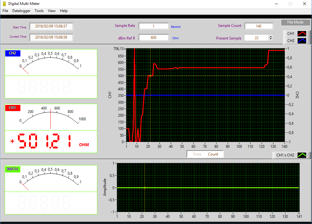
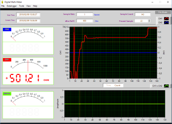
The software can show the two channels and a math channel, both as digital, analog and curve, but no tabular display.
The above is with CH1 on.
It is possible to activate the button functions from the software.

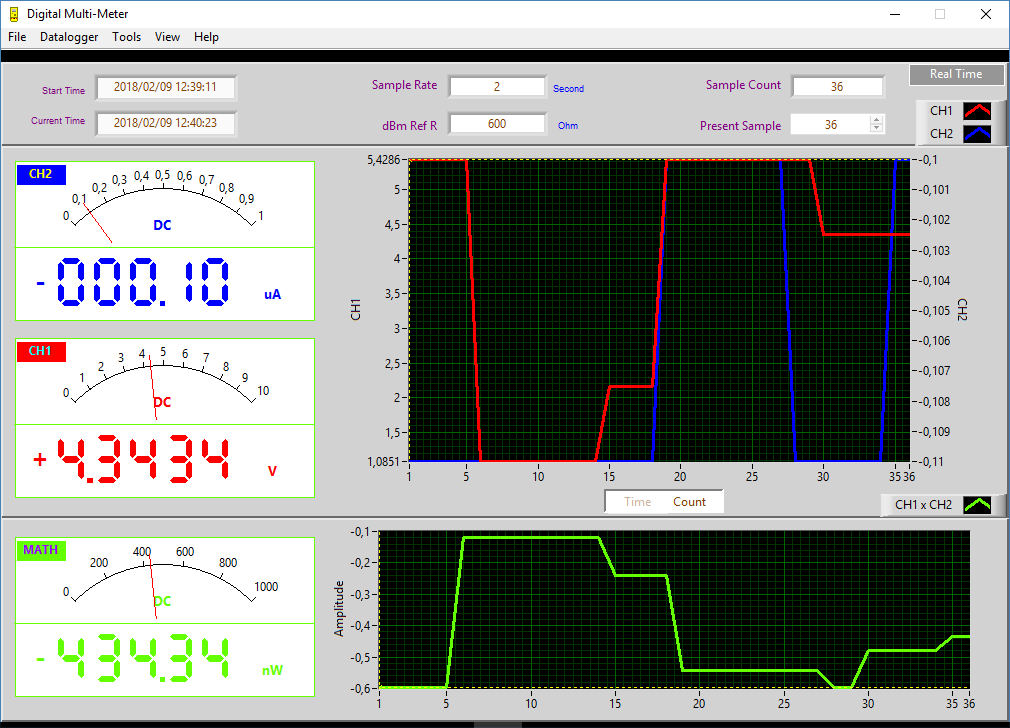
Here I have both CH1 and CH2 on and the math channel will be calculated.
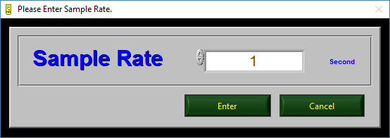
The sample rate can be adjusted and it is recommend to use 2 seconds or slower when logging both channels.
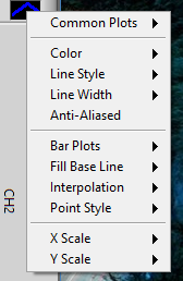
The design of the curves can be adjusted in many ways, this adjustment menu is present for CH1, CH2 and MATH channel.
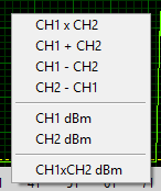
It is also possible to select what the math channel do, at least to some degree.
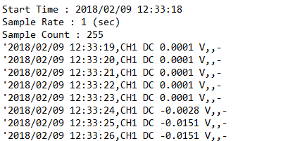
The CSV file is not a CSV file, each line start with a quote.
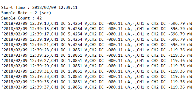
Both dual display and math channel is logged when on.
The meter can record data on its own and it can later be fetched with the software. When fetching data the software ask about when the data was recorded and will then add timestamps to the values.
This time I used the cursors to select a specific data point, the readout will show this value.
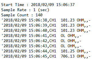
The saved data looks like above, but the timestamp is based on the time I entered.
The meter can log for nearly 6 hours with a reading each other second.
The communication protocol is documented in the manual and is very simple.
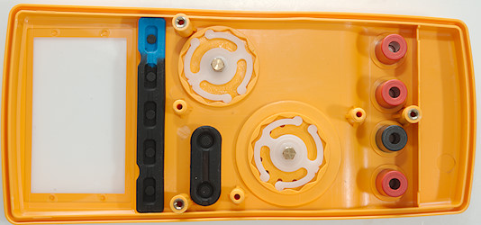
Tear down
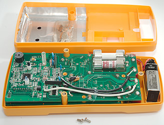
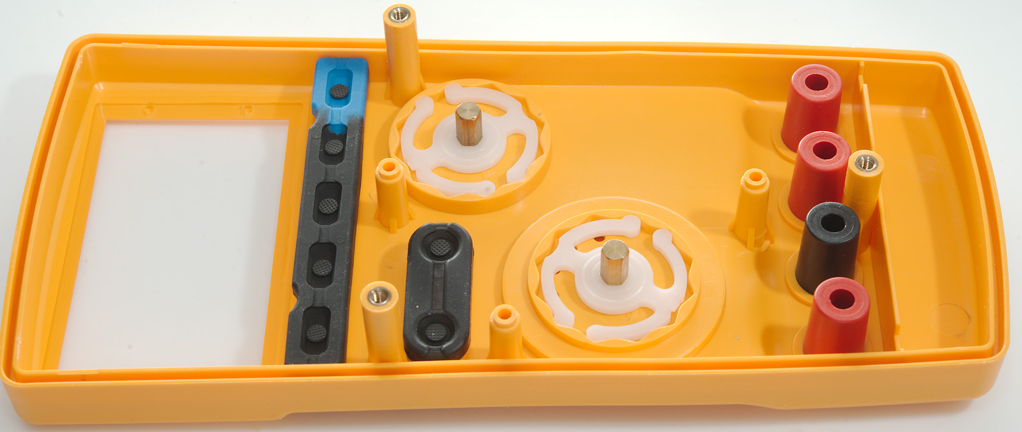
The battery cover and two more screws must be removed to open the meter.
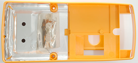
There is some shielding with holes for IR communication in the back.
The top circuit board takes up all the space inside the meter. The screws looks like they are connections to the lower circuit board.
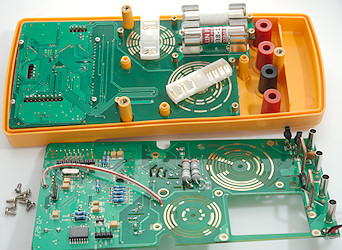
I had to remove 8 screws before I could get the circuit board out. The range switch bars can just be pulled off, but it is a good idea to get them on in exactly the same position and the right way around!
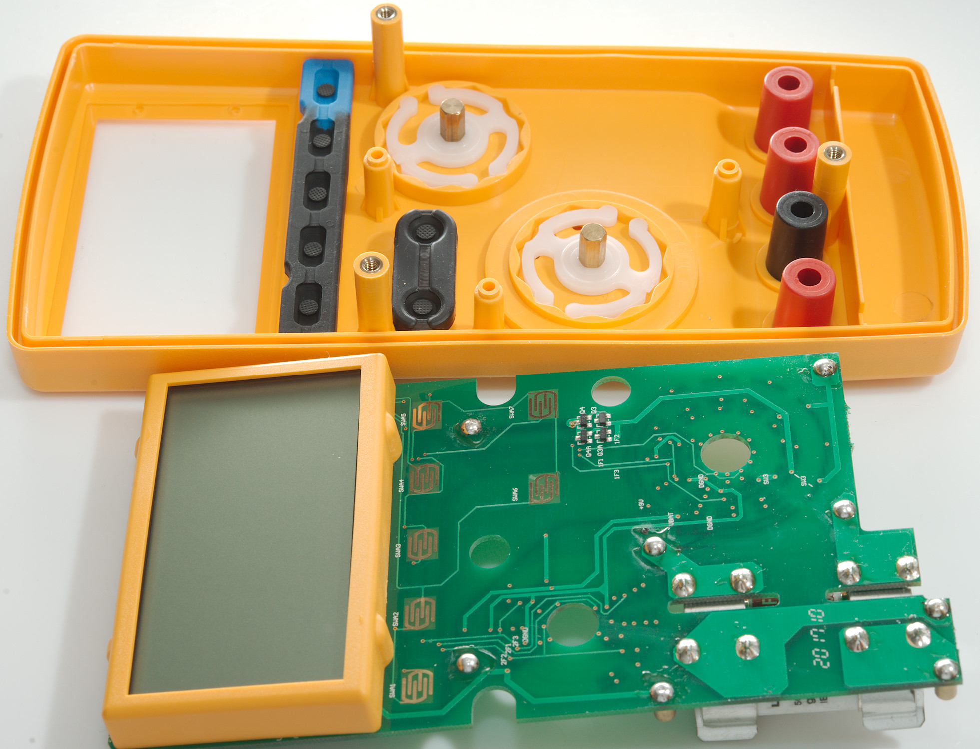
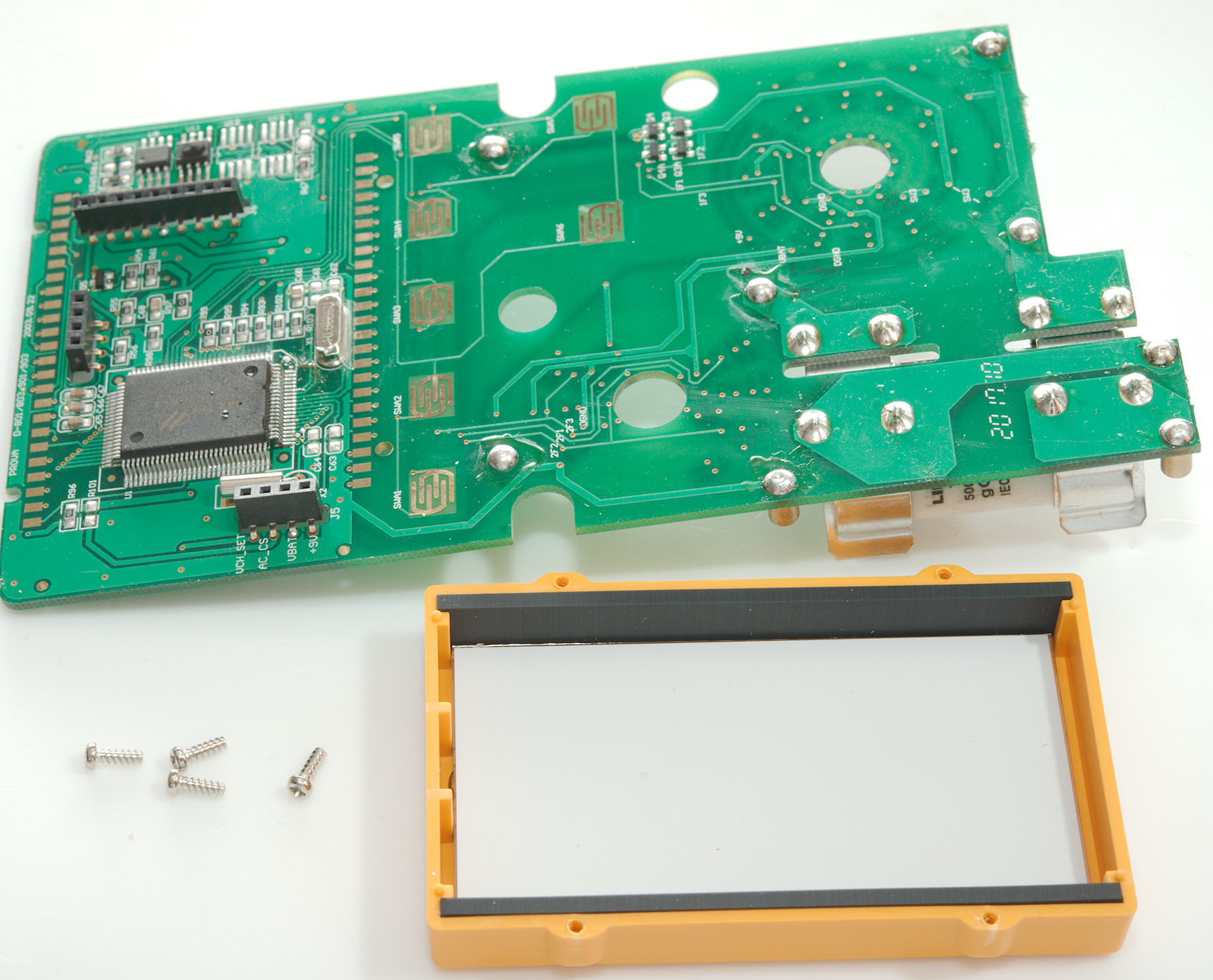
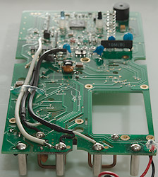
The lower circuit board could just be pulled out.
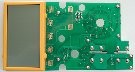
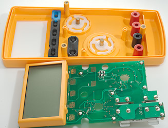
On this side is pads for the buttons on the front and a pair of protection transistors.
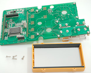
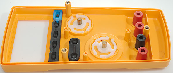
Four more screws and I could remove the display, be careful with the orientation of it.

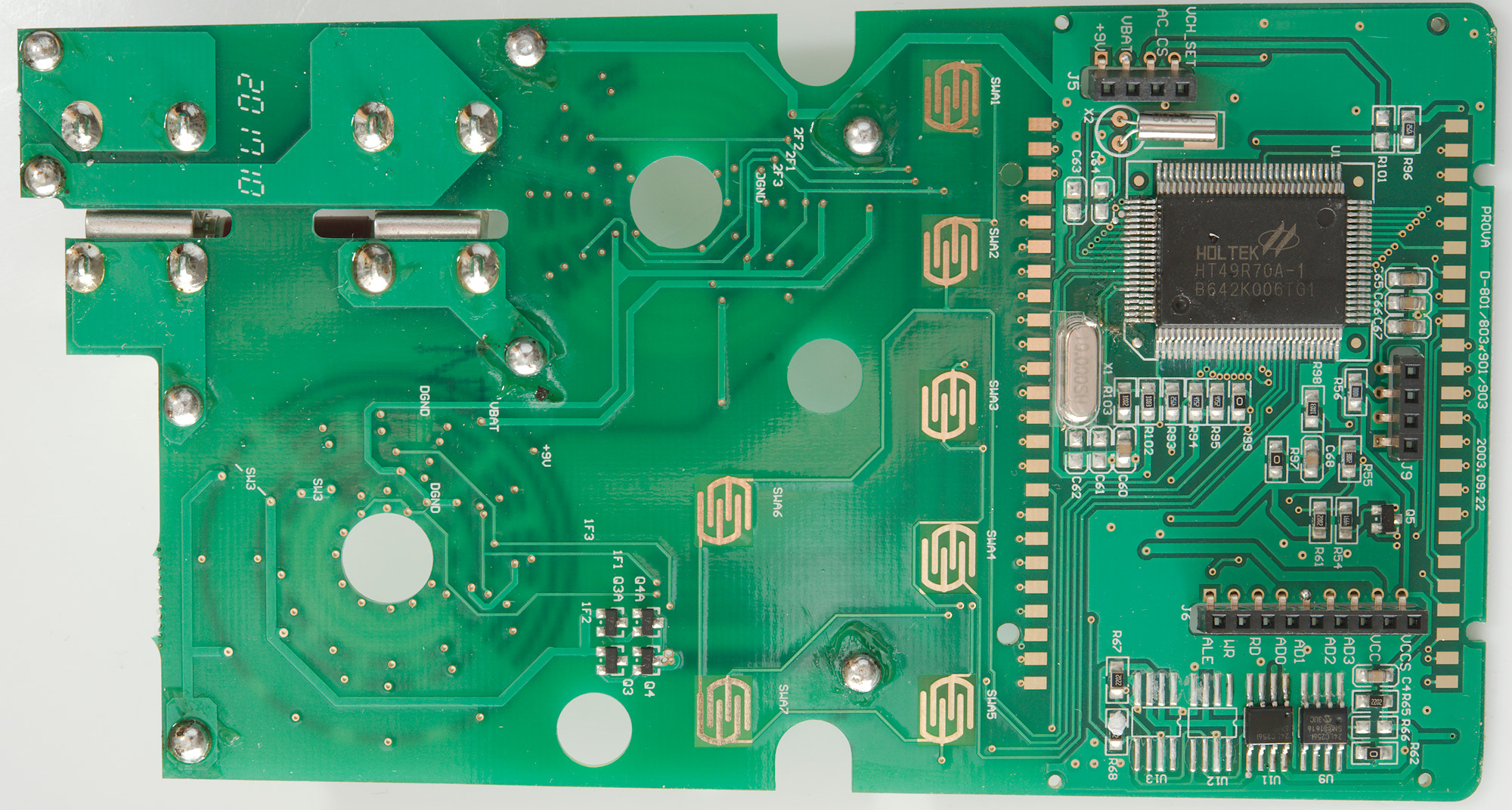
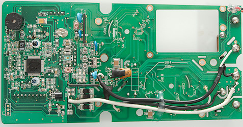
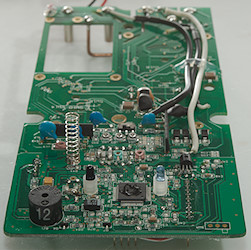
Here is a HOLTEK HT49R70A-1 8 bit RISK processor with 8Kx16 program memory. It runs at 10MHz. There is als two EEPROM chips (U9 & U11: 24LC256 32Kx8), probably used for the 10708 dataset log.
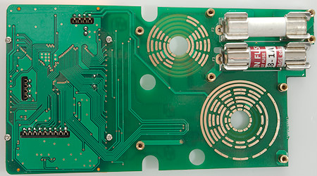
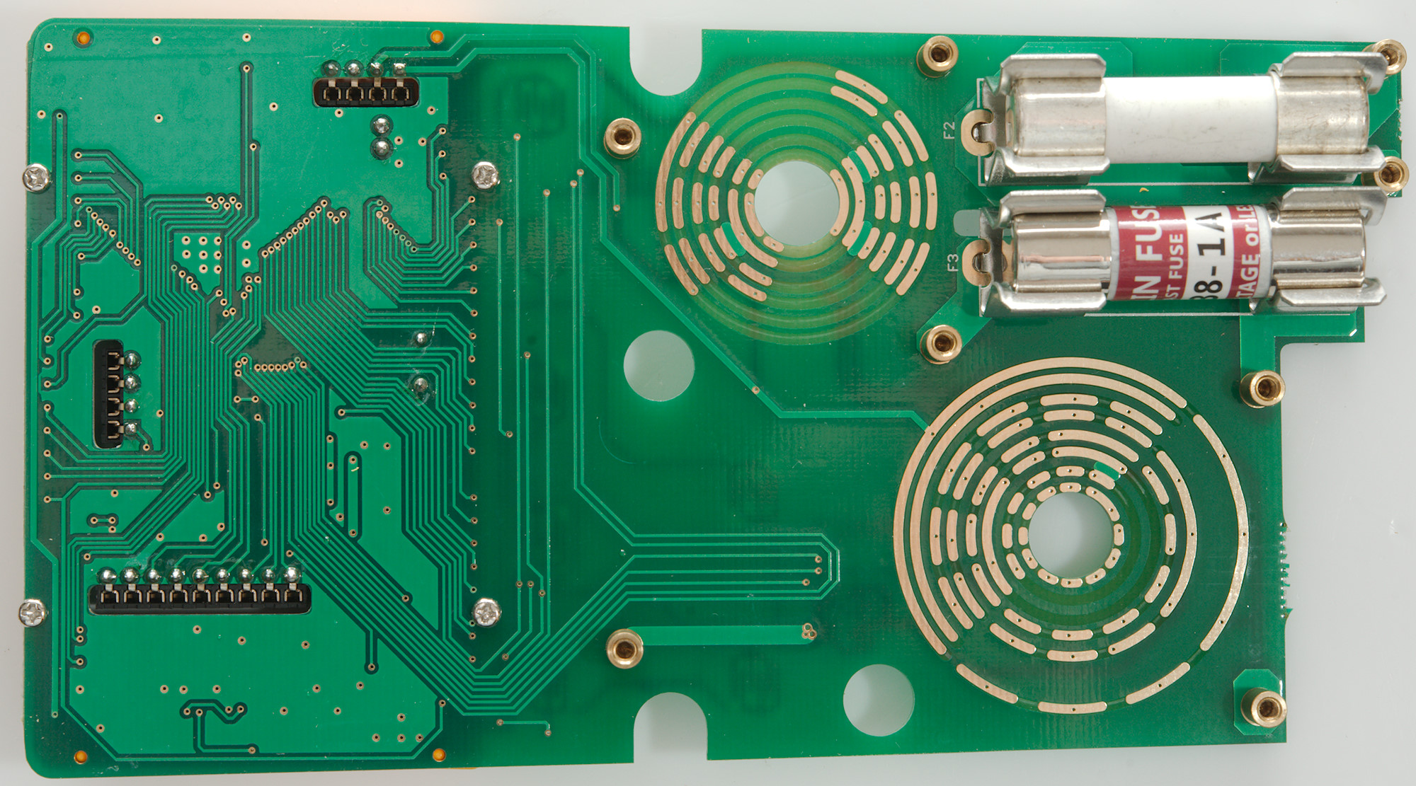
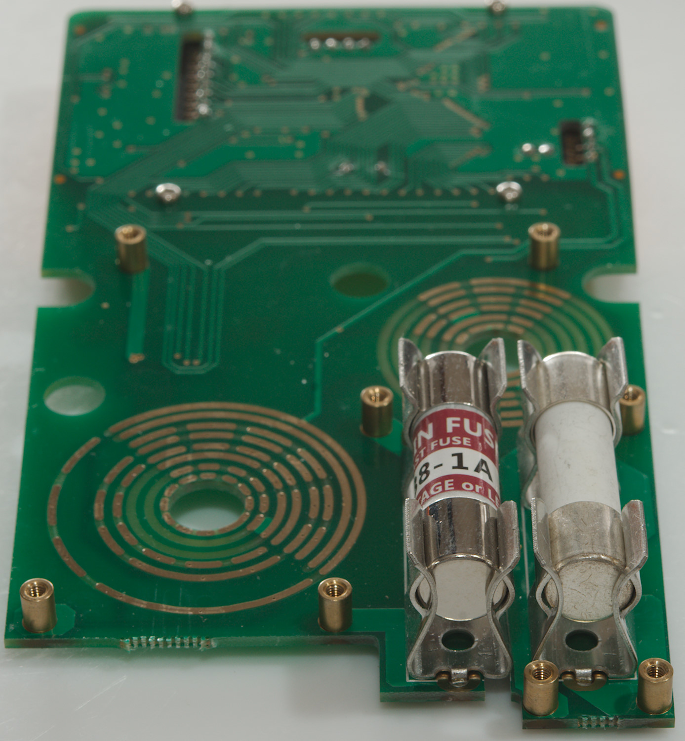
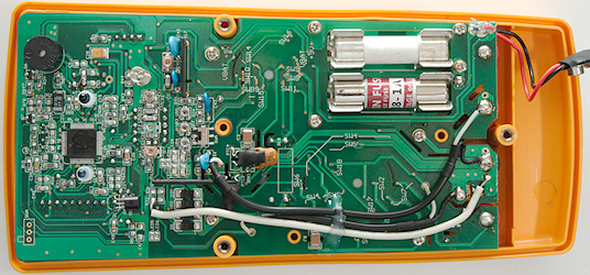
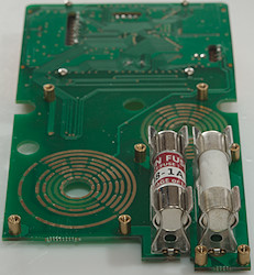
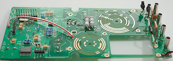
On the other side is part of the range switch and the fuses.
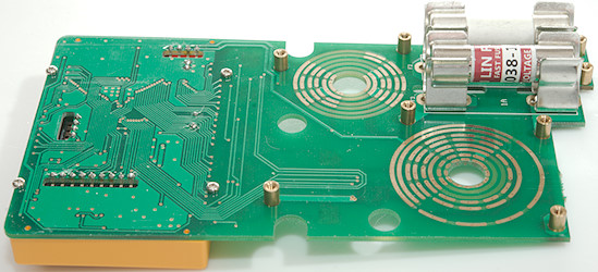
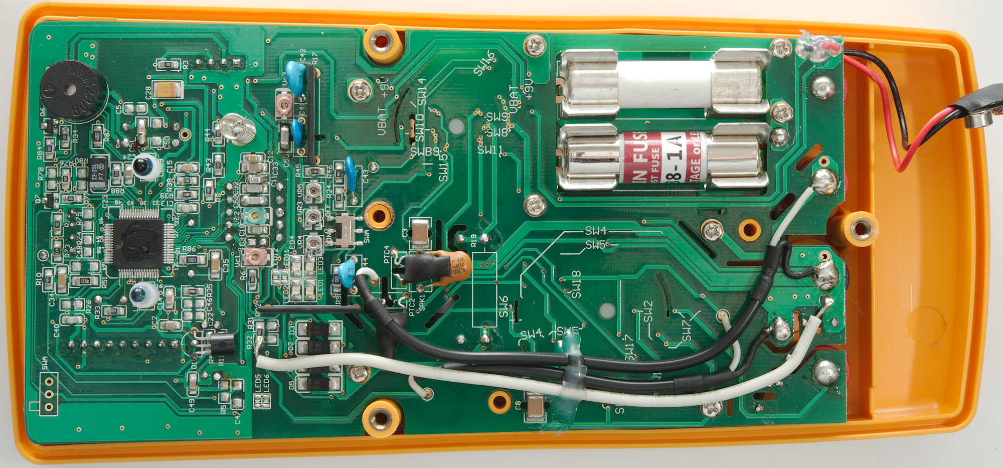
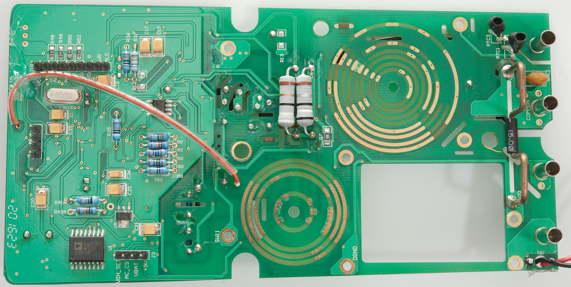
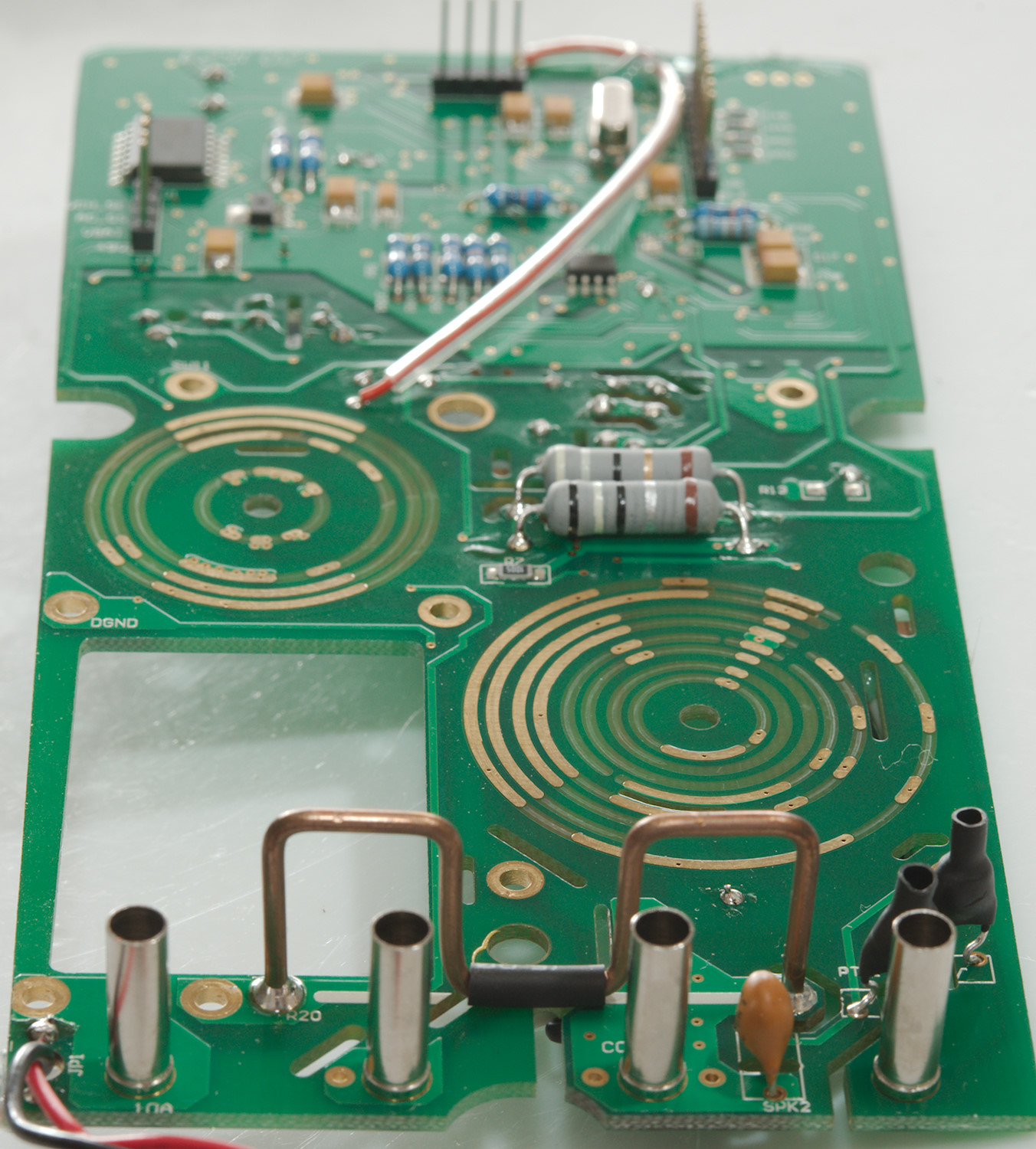
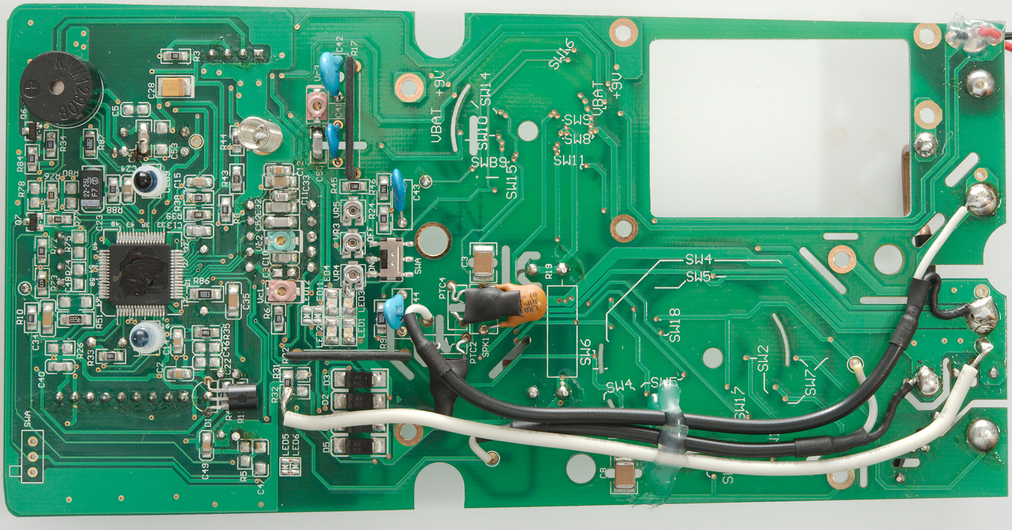
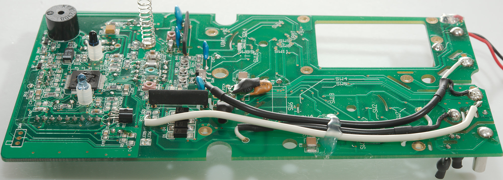
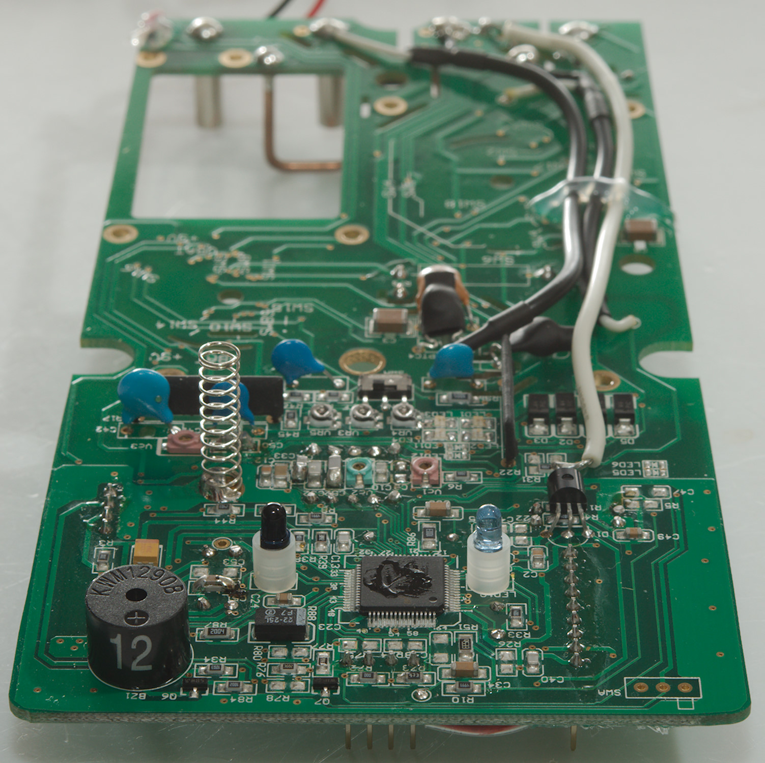
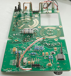
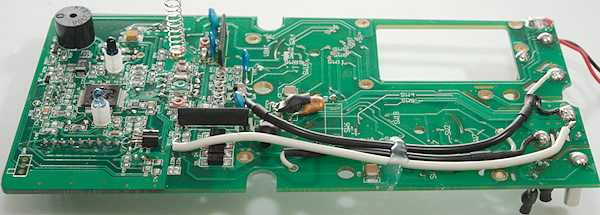
This circuit board is the analog and converter board. On this side there is two PTC's and a MOV near the V input terminal. The 10A shunt is very large (good) and the mA and uA resistors also looks fairly large.
The input mux (U3: DG419) that switches between the two inputs is partly hidden below the red wire. The large chip (U1: AD637) is the rms converter.
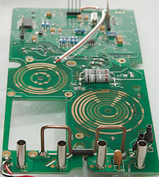
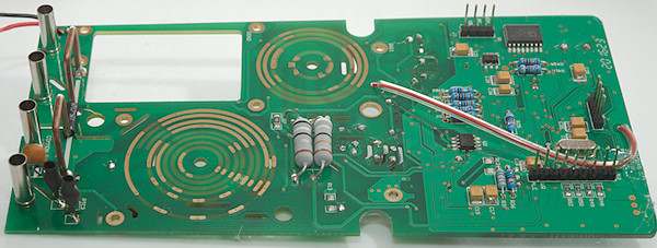
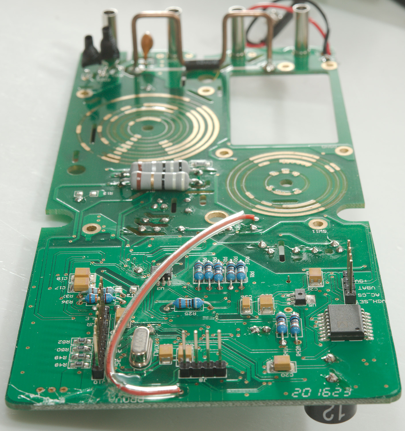
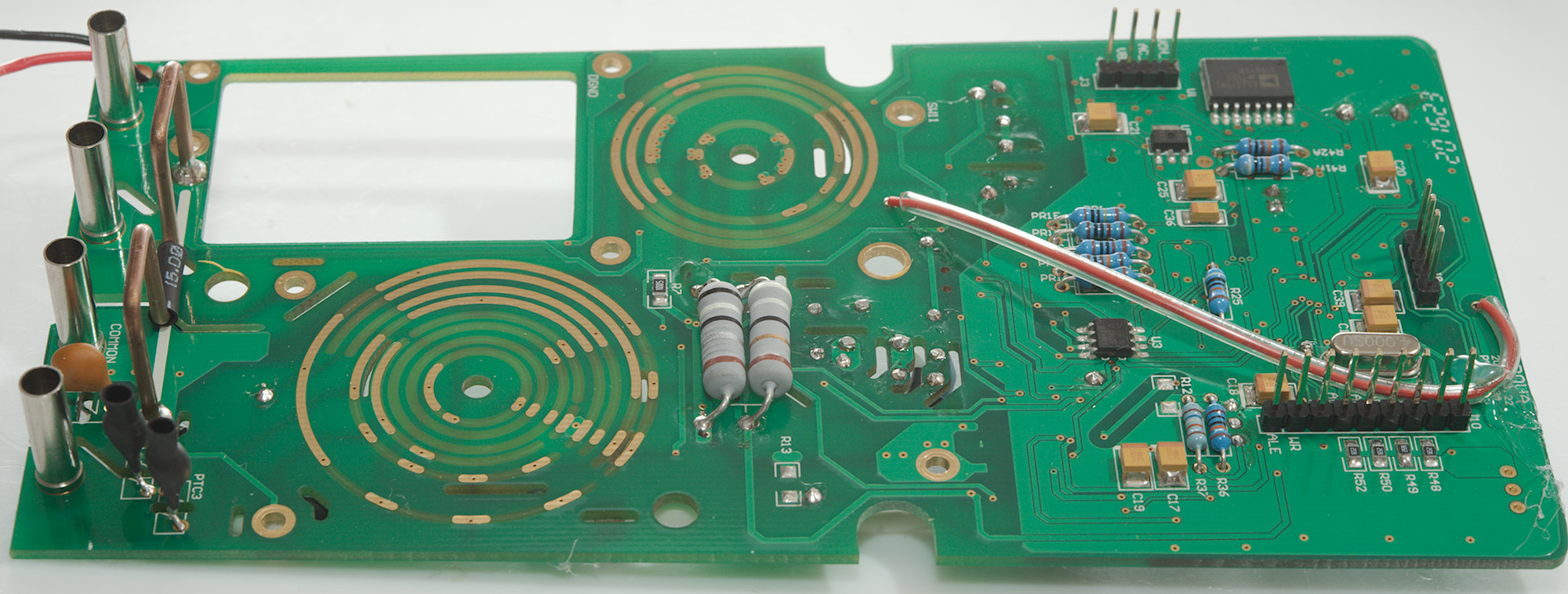
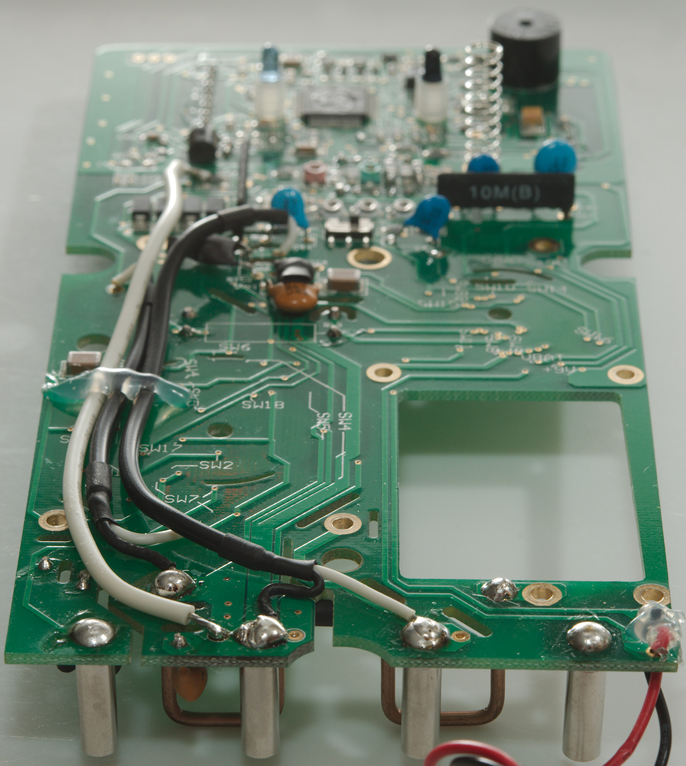
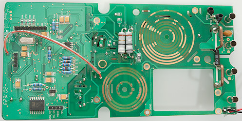
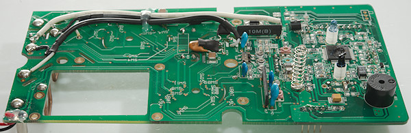
On this side are two PTC's more and a MOV, but they are not at the input terminal, instead the signal is wired halfway up the circuit board. It is interesting that one of the input resistors (R17: 10Mohm) has capacitors in parallel (This is done to improve the frequency response). There is both trimpot, but also trim capacitors and a switch (SWA in off position). It looks like some of the input protection is done with red leds. There is 4 diodes to protect the current shunt.
The number on the multimeter front-end chip is not visible.
Conclusion
It is an interesting idea to basically make two meters in one, but the solution is definitely not perfect here, the meters are rather slow, both to use and when logging.
It has good selection of ranges and functions, but are missing a bit for a high-end meter (Like average and AC+DC), I am also missing the backlight.
The missing warning when a battery is low, together with a significant error in displayed values is problematic.
I like that the software has a math channel and it is possible to calculate some values, this can also be used when meter has done some stand-alone logging.
I will not say that this meter can replace two meters (Remember COM is shared), but for some application it is better than one meter.
Notes
How do I review a DMM
More DMM reviews