DMM SNDWAY SW-890C
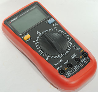
If you insist on manual range, this meter has a fairly complete set of ranges with a manual range switch. They have cheated a bit capacitance and frequency is auto range.
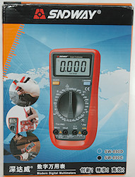

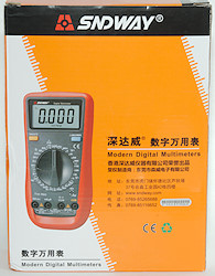

The box is in Chinese and covers both the C and D model of this meter (C includes temperature, D do not). The supplied instruction sheet was in English.
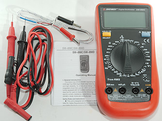
In the box was the meter, probe leads, thermocoupler and an instruction sheet. The instruction sheet is for both C and D models.


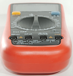
The standard probes are normal sizes and rated for CAT III 1000V and CAT IV 600V, but this cannot be a correct rating, because they are missing tip covers.
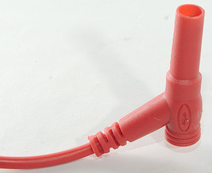
The plugs are fully shrouded and standard probe size.
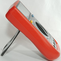
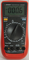
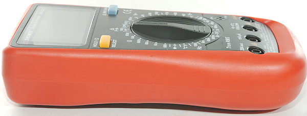
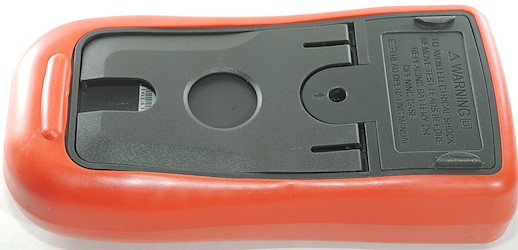
The range switch is easy to turn, this means it can be turned single handed both when meter is lying on the table or standing on the tilting bale.
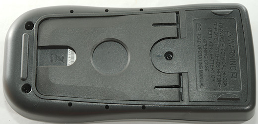
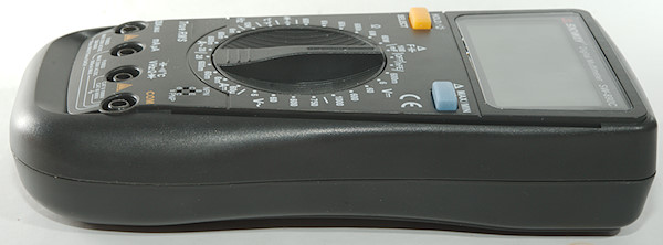
Display
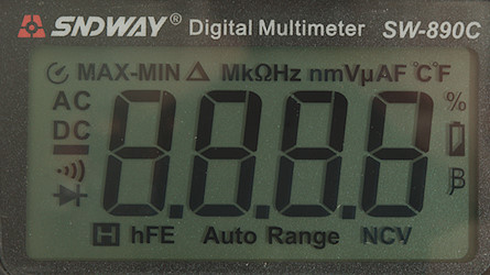
All the segments are shown during power on.
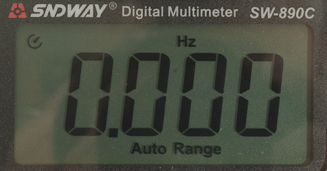
Typical display during usage, it will show the number and selected measurement
Functions
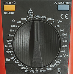
Buttons:
- Hold/Select: Will freeze the display reading, until pressed again. Except in diode/continuity it will select between diode and continuity and in temperature mode it will select between Celsius and Fahrenheit.
- Max/min: Selects max/min/max-min in most modes, in capacitance it will zero the reading.
Rotary switch:
- Off: Meter is turned off
- hFE: Transistor gain
- VDC: 600mV, 6V, 60V, 600V, 1000V: DC voltage ranges.
- VAC: 750V, 600V, 60V, 6V: AC voltage ranges.
- DCA: 60u, 6m, 60m, 600m, 20A: DC current ranges.
- ACA: 20A, 600m, 60m, 6m: AC current ranges.
- Hz 10M: Frequency ranges (Meter will auto range).
- °C °F: Temperature range
 : Diode and Continuity.
- Ohm: 600, 6K, 60K, 600K, 6M, 60M: Resistance ranges
- F: Capacitance range (Meter will auto range and max/min blue button can be used to zero range).
Input
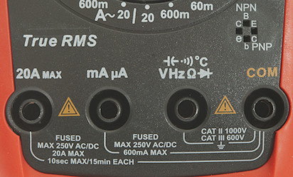
The COM terminal is not in the usual place!
- 20ADC: 20A current input.
- mA uA: Lower current input.
- xxx: All other ranges
- COM: The common terminal for all ranges
- NPN/PNP: Transistor tester input.
This is not the common placement of terminals.
Measurements
- Volt and frequency
- 5V AC readings is 5% down at 2kHz (RMS will not work at this frequency).
- Input impedance is 10-11Mohm
- Input impedance is high in 600mV range up to 1.5V where it drops to 100kohm
- At 100mVrms input frequency range is from 1Hz to 3.6MHz
- At 1Vrms input frequency range is from 1Hz to 47MHz
- Frequency counter requires a zero crossing.
- Frequency input resistance is 2-5Mohm below 2V, above it drops to 2kohm.
- Input protection is 750V AC or 1000Vpp
- Current
- 10A range protected with a 20A/250V 5x20mm fuse
- mA rnage is protected with a 0.63A/250V 5x20mm fuse
- 20A range has an audible alarm at 10A or above.
- Ohm, continuity, diode and capacitance
- Ohm needs about 1s to measure 100ohm (Manual ranging has a speed advantage)
- Ohm voltage is 1V open.
- Ohm current is 275uA in 600ohm, 79uA in 6k, 9.6uA in 60k, 0.9uA in 600k, 0.1uA in 6M and 60M
- Continuity is very fast (About 3ms).
- Continuity beeps when resistance is below 50ohm.
- Continuity is 1V open and 0.27mA shorted
- Diode range uses 3.2V, max. display is 3.000V at 0.1mA, max. current is 1.1mA shorted
- Overload protection is 600V AC
- Miscellaneous
- Current consumption of meter is 3.5mA, but selecting frequency will switch to 1.3mA in all ranges.
- Meter turns off at 2.2V, battery symbol show at 7.5V.
- Backlight fades with dropping voltage and is nearly out at 3V.
- Readings are correct until the meter turns off.
- Viewing angle is good
- Display updates around 3 times/sec
- Backlight will automatic turn off in about 15 seconds.
- Will automatic turn power off in about 15 minutes.
- Standard probes fits in the meter.
- The meter usual need a couple of display update to reach the final value.
- Weight is 322g without accessories, but with sleeve and batteries.
- Size is 185 x 89 x 40mm
- Probes
- Probe resistance 43mOhm for one.
- Probe wire is 93cm long.
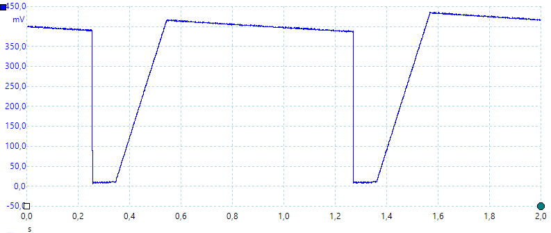
A look at the capacitance measurement waveform for 1uF.
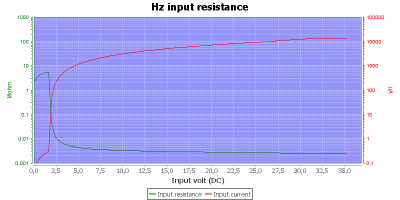
Frequency input resistance.

Tear down
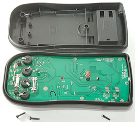
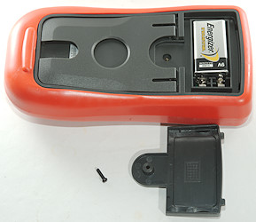
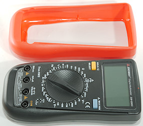
I had to remove 3 screws top open it, one of them was the battery cover screw.
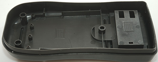
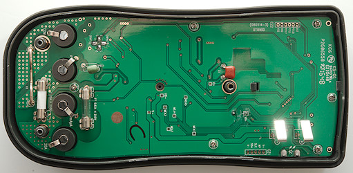
The circuit board is shaped after the enclosure.
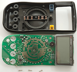
3 more screws and I could remove the circuit board. These screws was very tight.
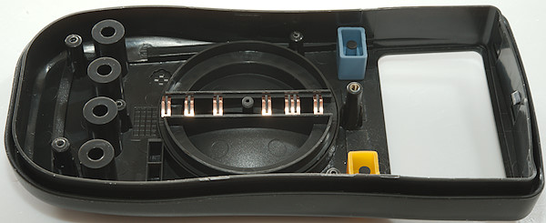
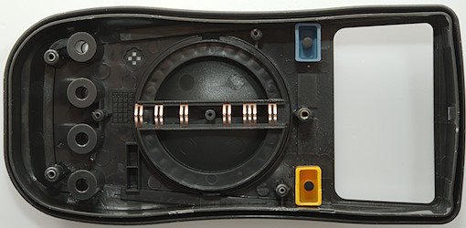
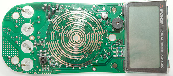
The display is mounted with 3 screws and a clip.
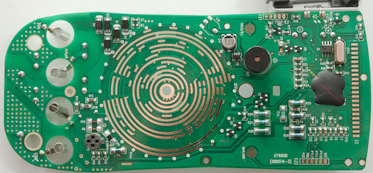
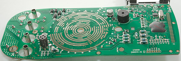
Some of the input circuit is very obvious to see here. The volt input has 3 "legs", one with 3 resistors (R1A, R1B, R1C: 3x300k), one with a PTC (PTC1 on the other side) followed by protection (Q5, Q6 and Q1, Q2 in some cases) and one with four resistors (R2A, R2B, R2C and R2D: 4x2.5Mohm).
The uA and mA current range has diodes (D1..D5) for protection.
U2 is probably a EEPROM to store calibration in.
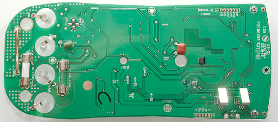
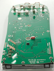
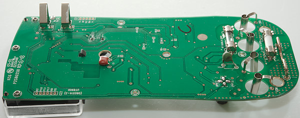
On this side of the circuit board is not much. There is the two fuses, one of the glass. The PTC for protection the ohm and capacitance range and a single capacitor.

Conclusion
The CAT rating do not match the fuses used, i.e. it is not correct, but at least it use fuses.
For a "simple" meter this is fairly well designed, AC/DC volts works properly and it has some input protection. It has good specifications and it looks like it stays within the specified tolerances.
Notes
This meter may exist with many different names on it and small variations in functions.
How do I review a DMM
More DMM reviews
 : Diode and Continuity.


 : Diode and Continuity.


