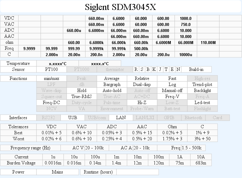
DMM Siglent SDM3045X
This is a low end bench meter, but it has many of the function of a high bench end meter, but not the resolution.
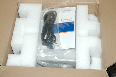
It arrives in a big very solid cardboard box with the DMM well protected inside.
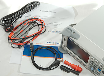
It includes the meter, a quick start guide, a calibration certificate stating that the meter is in calibration, mains cable, a pair of probes with alligator clips and a usb cable. It do not include any manuals, they must be downloaded.
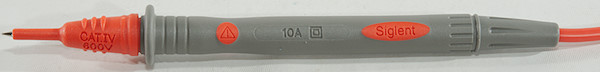
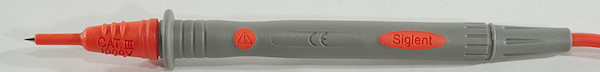
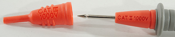
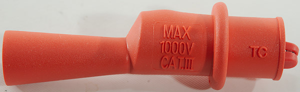
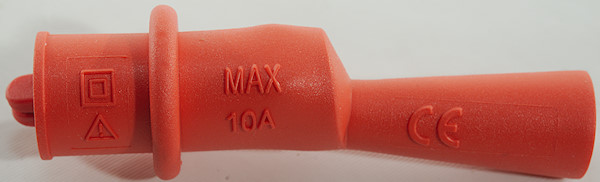
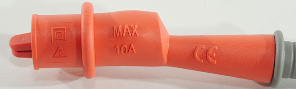
Standard probe, with good safety.
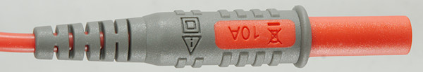
The plug is fully shrouded.
Isolated alligator clips to mount on the probes.
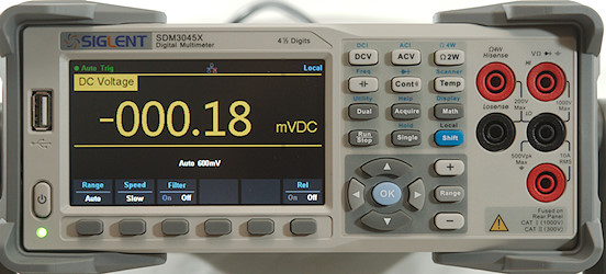
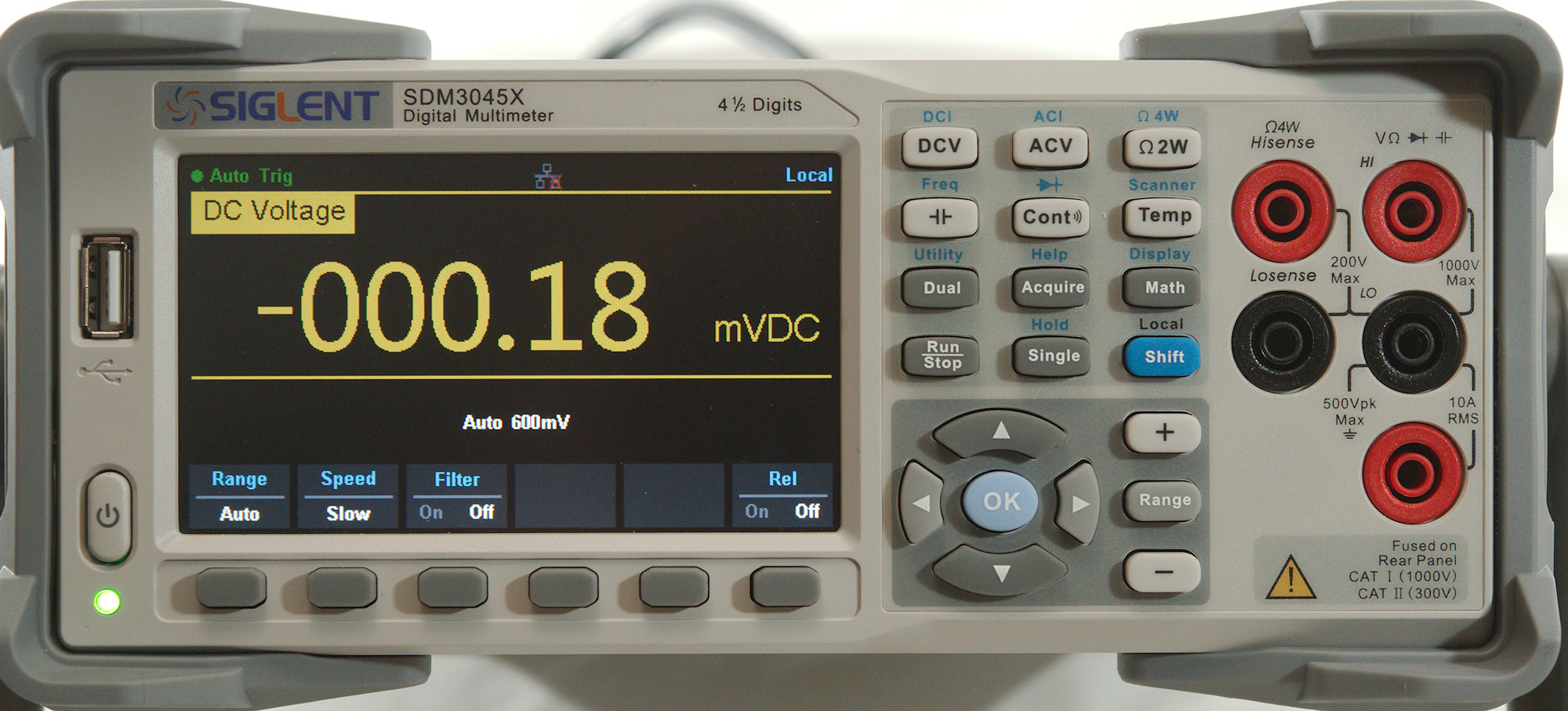
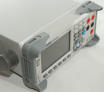
The front has the display, the buttons and the input.
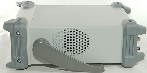
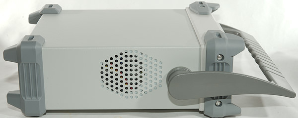
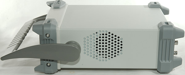
There are vent holes on the sides, but the meter do not have a fan.
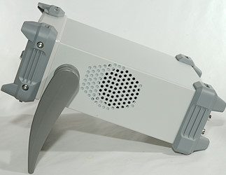
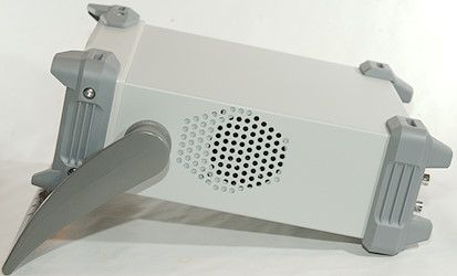
The meter can be tilted in two different positions.
With the handle at the front the meter is ready to be carried.
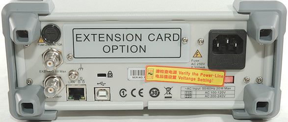
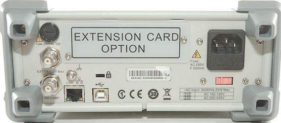
The back, there was a warning to check the mains voltage.
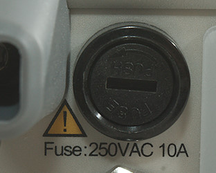
The input fuse is on the back of the meter.
Display

This meter is a computer that needs some time to boot and do self test, during that time it shows the brand name. Total time is about 16 seconds.
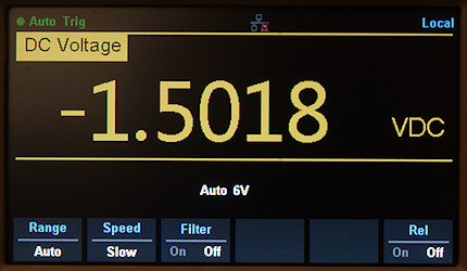
Typical display when measuring without any of the more advanced stuff activated. Here I am measuring a voltage.
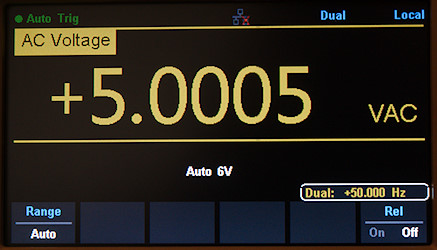
Secondary display enabled and showing frequency. Many function on the secondary display will mean a relay has to change mode of the meter. Any combination of VDC/VAC/IDC/IAC can be shown on the main/secondary display, the ACV can also be combined with frequency or period.
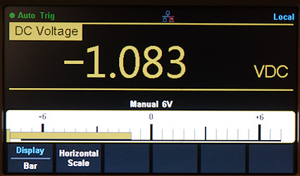
A bargraph can be enabled, it is possible to configure endpoints.
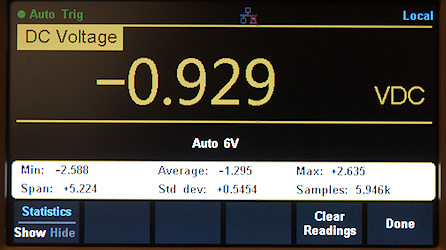
The statistic can show max/min/average and a bit more.
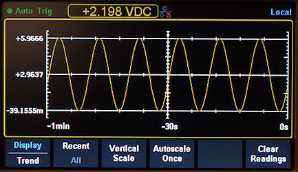
It is possible to show data as a chart.
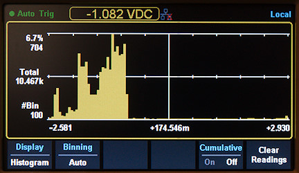
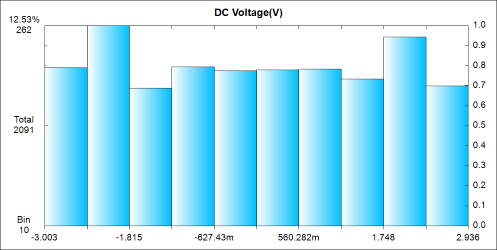
Or as a histogram with up to 400 bins.
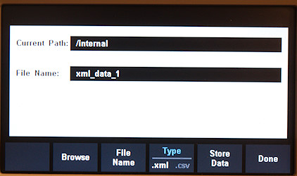
The collected data can be saved to usb, but it requires a number of button presses:
Utility, Store/Recall, Store settings, Browse, arrow down, Select, Type, Store Data, Yes, Done.
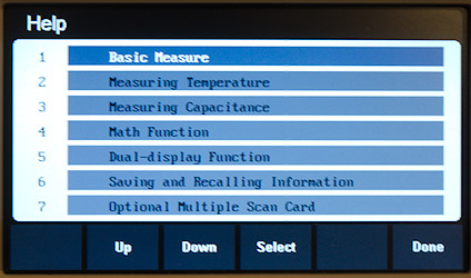
There is also a help system build into the meter.
Functions
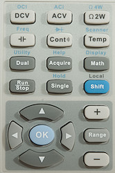
- DCV/DCI: DC voltage and current.
- ACV/ACI: AC voltage and current
- ohm 2W/4W: Resistance in either two or four wire mode.
 /Freq: Capacitance and frequency
- Cont/
 : Continuity and diode.
- Temp/Scanner: Temperature with either a thermocoupler or PT100 sensor.
- Dual/Utility: Select dual display measurement and save/configure/test/update.
- Acquire/Help: Set trigger and look in build-in manual.
- Math/Display: Statistic, Limits, DB, relative, bargraph, chart, histogram selections.
- Run/Stop: Select to measure or not.
- Single/Hold: Trig a single measurement and enable auto-hold mode.
- Shift/Local: Access all the blue functions and cancel a remote connection (Local only need a single press on the key).


 : Selection and adjustment in various menus.
- OK: Confirmation of selection in menus.
 /Range/
 : Change between auto range and manual range and select range.
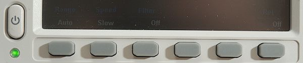
The 6 keys below the display are soft keys and the actual function will be listed on the display.
The power button is a soft switch, this means part of the meter is always on and using power.
A short press will turn the meter on a longer press will turn it off.
The led below the button is steady green while on and slowly flashing when meter is off.
Input
The inputs are only CAT II 300V rated, i.e. the meter is not designed for industrial and service on electric installations.
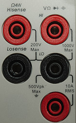
- HI: The voltage, frequency, capacitance, diode and ohm positive input.
- LO: The voltage, frequency, capacitance, diode and ohm negative input.
- HIsense: Four terminal ohm.
- LOsense: Four terminal ohm.
- 10A: Current input
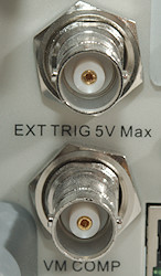
The trigger in input, this is on of the conditions that can be used to start a measurement. The VM comp will signal when a measurement is done.
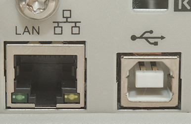
The usb and lan connections on the back can be linked to a computer for remote control and logging.
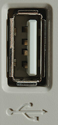
There is also a usb connector on the front, it can be used with memory sticks for saving data and configuration.
Measurements
- Volt and frequency
- At 100mVrms frequency input range is from 2Hz to 500kHz
- Frequency counter has a capacitor at the input and ignores any DC offset.
- 1 VAC is 5% down at 320kHz, rms will not work at this frequency
- Period is 1/frequency, it do not show high/low period time.
- Min/max captures in about 200ms on slow speed and 15ms in fast speed, but peak must match sample window.
- Min/max is based on normal measurements, there is no special mode/circuit to make faster captures, this is standard for bench meters.
- Meter can show dB with adjustable reference either measured or entered.
- dBm reference impedance has these settings: 50, 75, 93, 110, 124, 125, 135, 150, 250, 300, 500, 600, 800, 900, 1000, 1200, 8000,
- Input impedance is 10Mohm on DC, but only 1Mohm on AC with capacitor coupling.
- Frequency input is similar to AC input.
- mVDC range can be set to high impedance.
- The VDC range will toggle a relay, even when not changing range. This may reduce reading speed significantly!
- Current
- Current range is protected with a 10A/250V 5x20mm glass fuse accessible from outside.
- There is also a internal 12A/250V 5x20mm ceramic fuse for protection.
- uA range has very low burden voltage, it do not use the common 100ohm shunt.
- Auto range will disconnect shortly when changing from 6mA to 60mA range and 600mA to 6A range.
- Even in manual range the meter will auto range when a current range is overloaded.
- Ohm, Continuity, diode and capacitance
- Ohm needs about 2s to measure 100ohm in default slow and about 0.3s on fast.
- Ohm is up to 5.0V open and 1.0mA shorted
- Continuity is quick (About 30ms).
- Continuity beeps when resistance is below 50ohm, this is adjustable.
- Continuity is 5.0V open and 1.0mA shorted
- Diode range uses 5.0V, max. display is 4.000V at 1.0mA, max. current is 1.0mA shorted (Max. display is adjustable from 0 to 4V).
- Diode range maximum is adjustable, it follows selected threshold, i.e. with 2V as threshold meter will maximum show 2V (Silly).
- 10uF takes about 2.5 seconds to measure.
- 9700uF takes about 14 seconds to measure.
- Miscellaneous
- Power consumption when on is 9 watt
- Power consumption when off is 3 watt
- The meter reach final value in a few updates, extra updates is required when doing auto range.
- Viewing angle is good.
- Display update speed depends on settings (5, 50, 150 / second)
- Bargraph updates will follow the display update, this is normal for bench meters.
- At 150 readings/second the resolution will be reduced to 3.5 digit.
- The last 10000 measurement are stored in a internal buffer, this can be presented in various ways, saved to a usb key or downloaded.
- Weight is 3820g including bumpers.
- Size is 300 x 260 x 110mm including bumpers and handle.
- Probes
- Probe resistance 26mOhm for one.
- Probe wire is very soft and 98cm long.
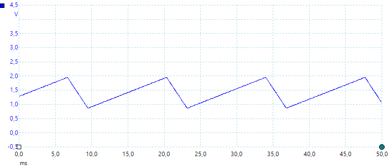
A look at the capacitance measurement waveform.
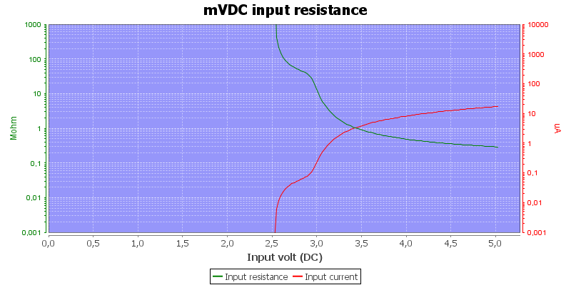
The mVDC range is fairly similar to handheld meters when in high impedance mode.
The data format saved to usb in very simple, no time, mode or anything, just the values.
High AC voltage can make DCV show to low value. AC input is capacitor coupled and will not be confused by DC.
The meter has trouble measuring close to 10000uF, it frequently shows overload.
When measuring 10Mohm resistance I can change the result 1Mohm by touching the cables (Using slow speed).
Software
This software is a free download from Siglent.
According to the installation manual you have to download and install NI-VISA yourself before installing this software, I already have this software on my test computer in the newest version and did not do anything.
The software is obvious for all Siglent bench multimeters and have lot of function for a meter with a multiplexer/scanner card, these are not relevant and do not work for this meter and I will not us them..
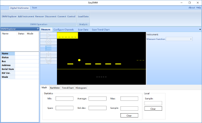
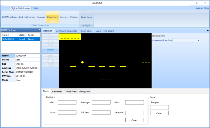
Starting the software with the meter connected gives a complex looking user interface without much contents.

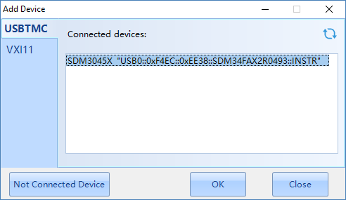
Plugging the meter in and using "Add instrument" makes it possible to select the meter.
Next time I start the software the meter will be listed and I only have to press connect. Once I had some problems that I could not start the meter after a connect, removing the meter and adding it again fixed that.
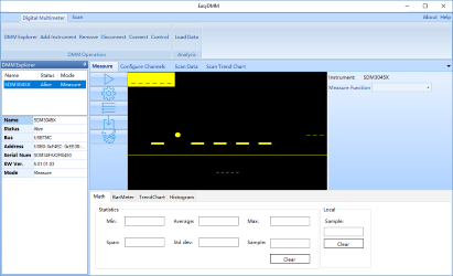
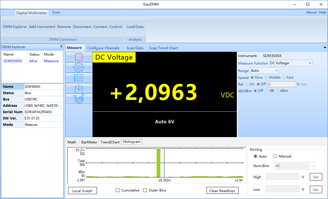
Meter is connected and ready, press the start triangle and it is gathering data.
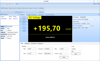
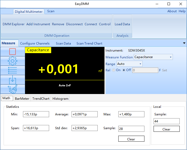
Many of the meter functions are directly available here, but the check is not as stringent as on the meter, I could select dB for DC.
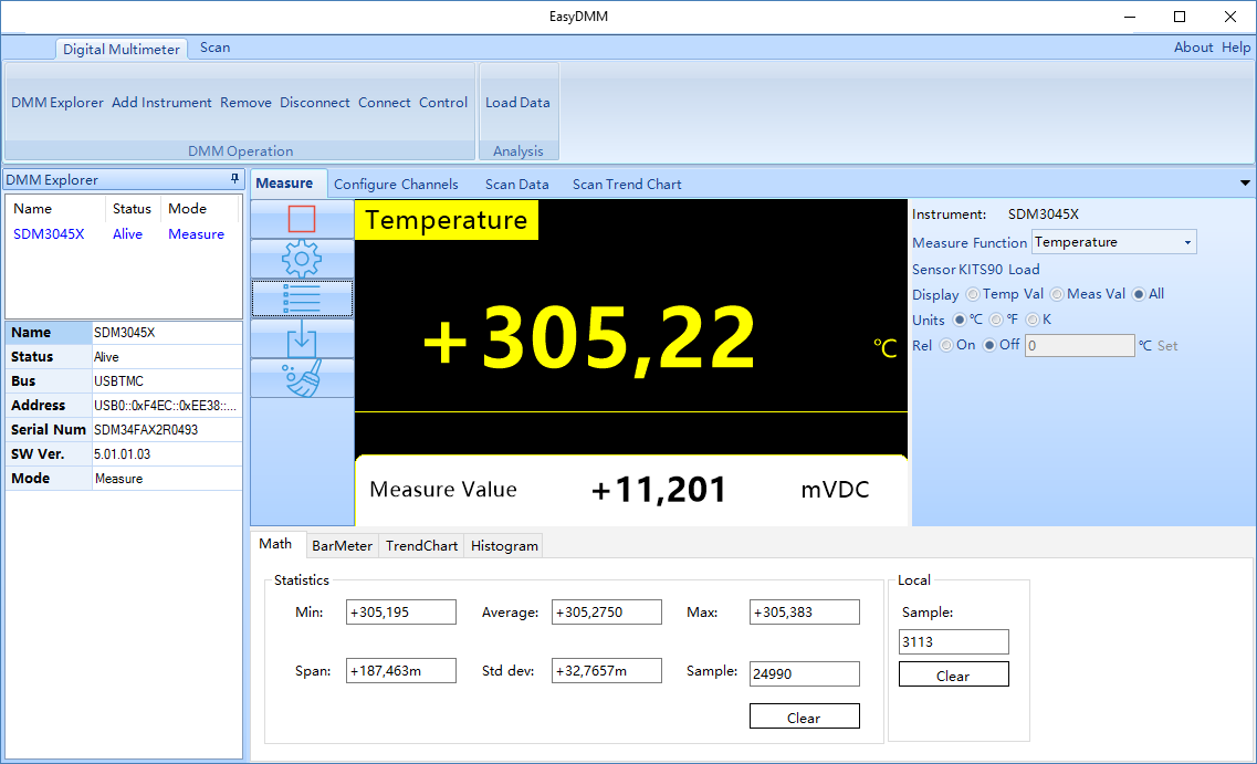
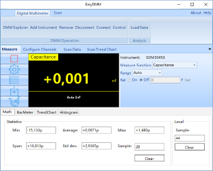
At the bottom is the statistic function.
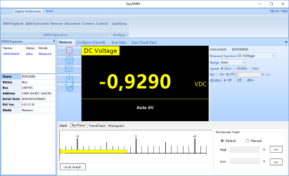
The bottom can also show the bargraph.
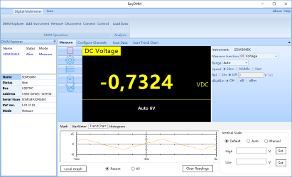
Or a chart

And the histogram.
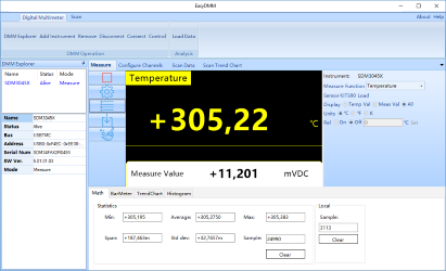
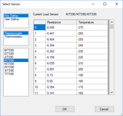
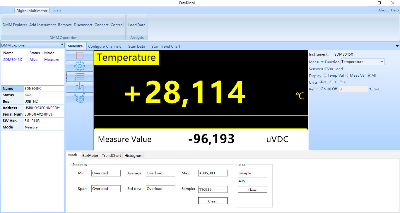
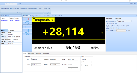
The temperature function with all selections from the meter available.

It is possible to view the thermocoupler definition. The heading of the table is wrong, it is voltage (millivolt), not resistance.
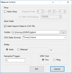
The gear button beside the meter display has some configuration, including local logging of data.
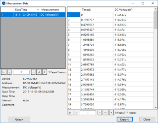
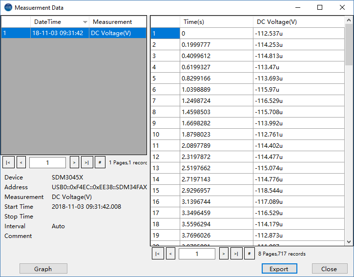
When the software is running it will collect a local log, these can be viewed and saved.
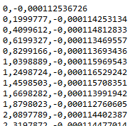
The saved data is a very simple format (The actual time format can be configured) and has the usual bug with point and comma. I will be very hard to read this data because comma is used both as a decimal point and as a delimiter.
The filename will match the meters mode, i.e. when measuring DC voltage the filename will include "DC Voltage(V)".
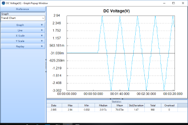
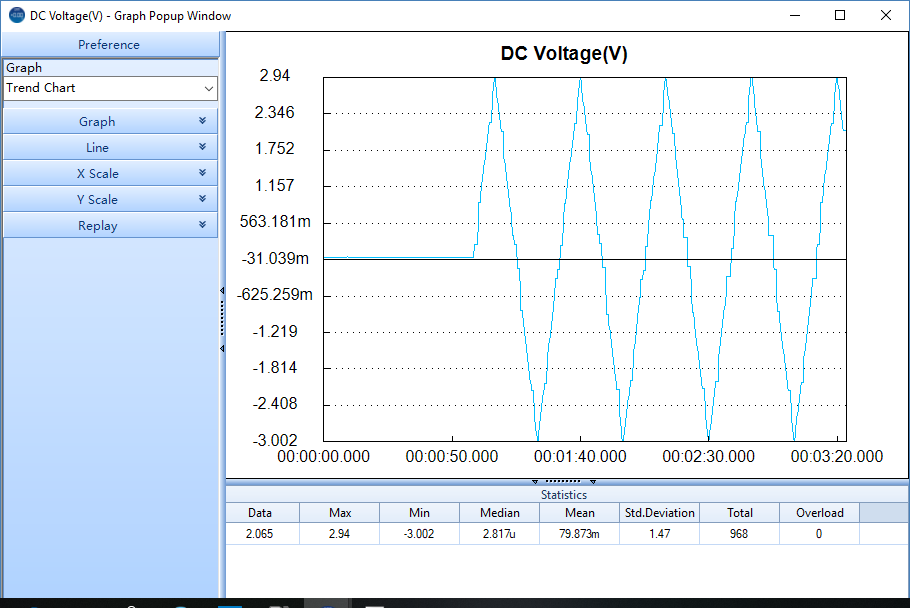
The viewing of the local logs also includes a chart
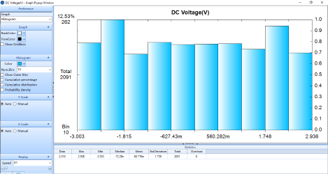
Or a histogram. There is a lot of settings on this chart and the window can be resized.
The chart can also be saved to disk or to clipboard.
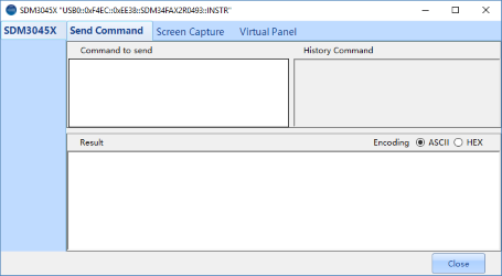
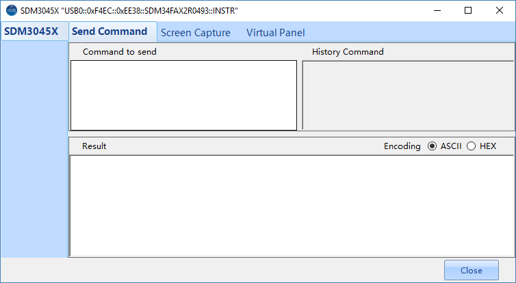
The "Control" button in the interface opens other ways to use the meter, here a direct SCPI interface.

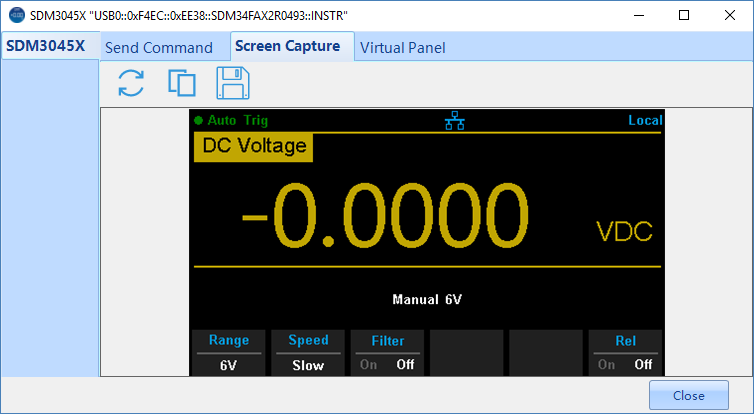
Fetching of screen dumps. This function is not synchronized with display updates.
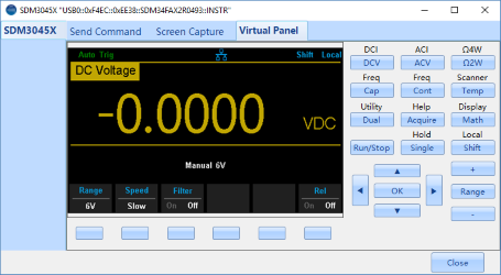
A virtual front panel.
This interface can scale fairly well and the "DMM Explorer" window can be moved outside the main application.
Tear down

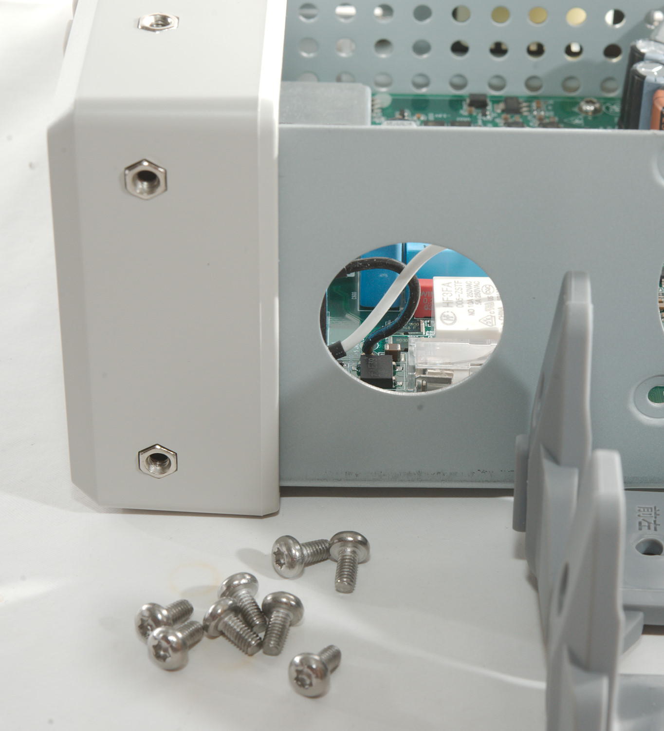
Four screws at the back bumpers and one at the bottom then the lid was loose, but I also had to remove the handle (Turn it to the right angle and pull out), before I could pull the lid off.
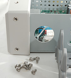
The front bumpers each has four screws, but it do not open anything up. It is probably for brackets that can be used for rack mounting.
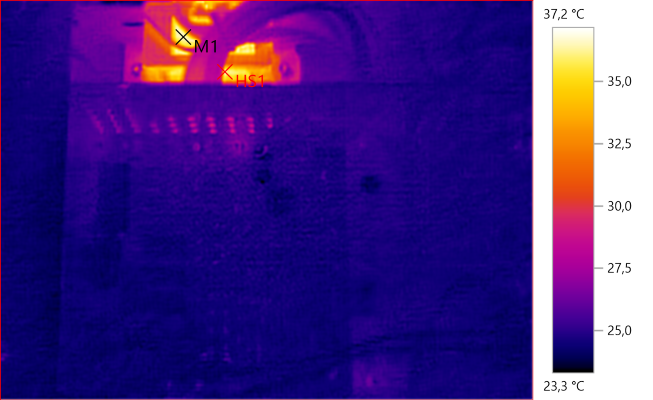
M1: 36.4°C, HS1: 37.2°C
When turned off it is only the transformer that uses power.
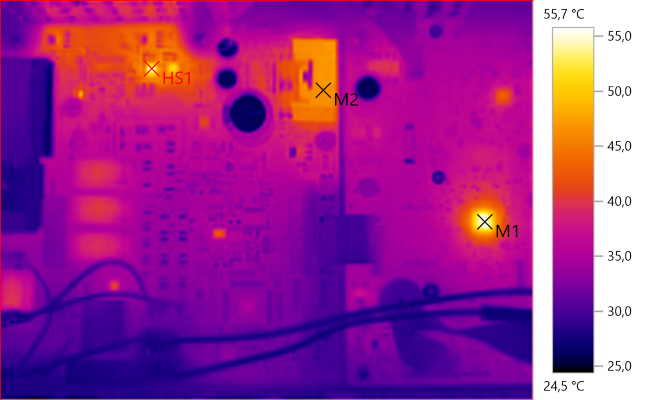
M1: 55.3°C, M2: 46.5°C, HS1: 55.7°C
When on the processor and the +/-15V voltage regulators get a bit warm.
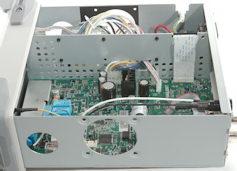
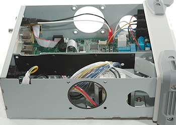
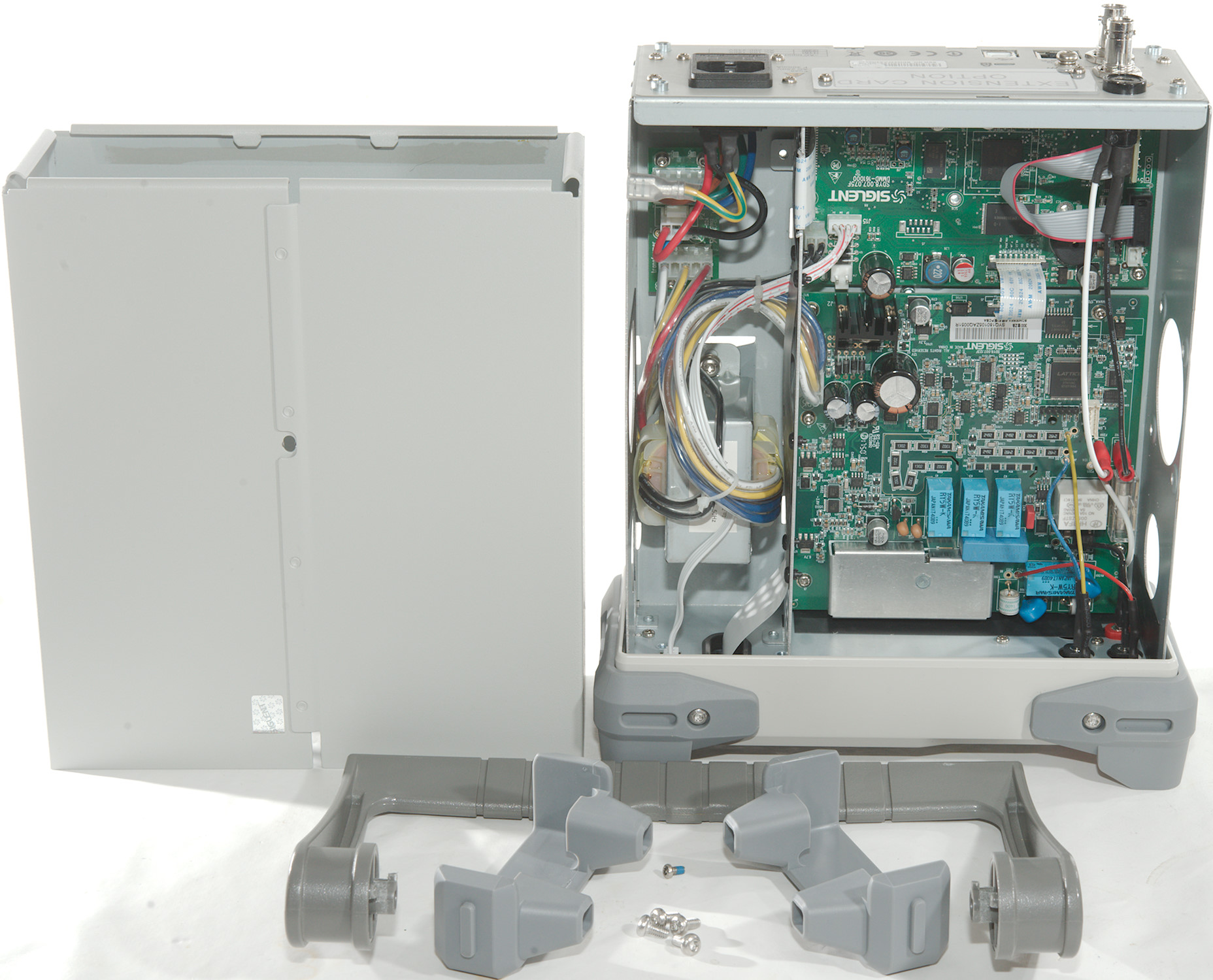
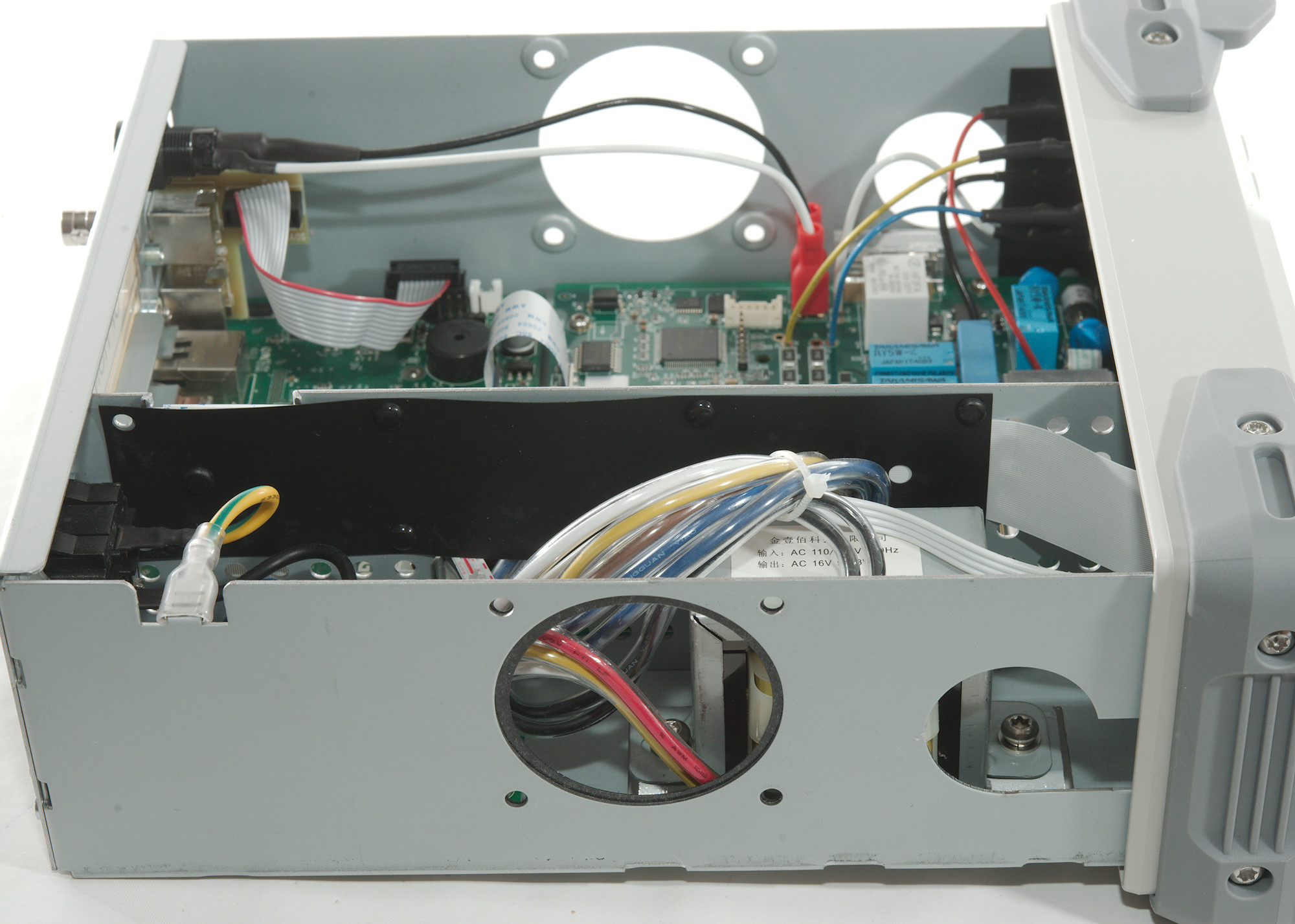
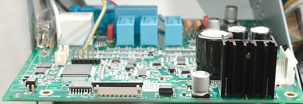
The meter is in two parts, one for the transformer and one for the electronic. It is without a fan.
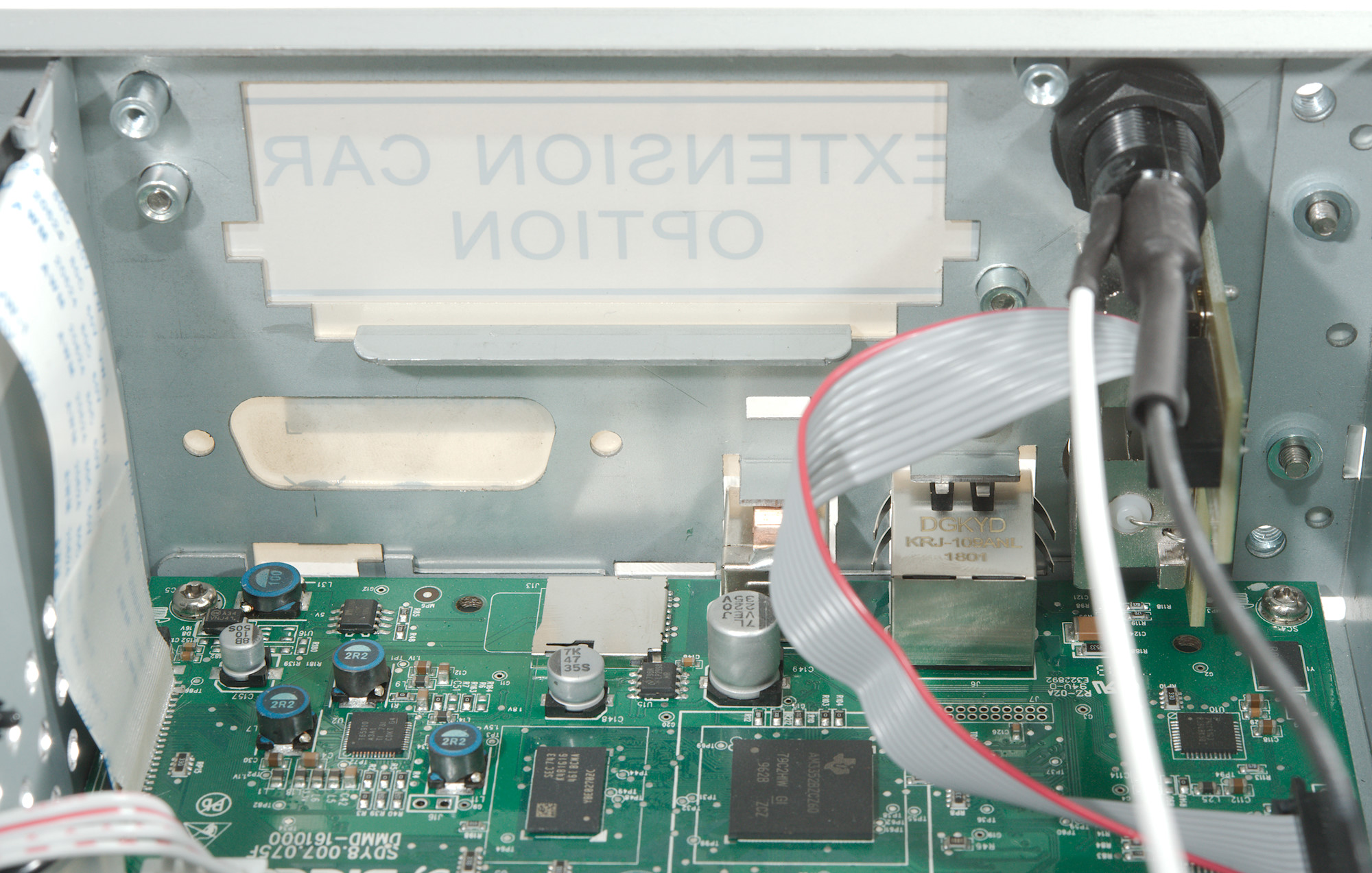
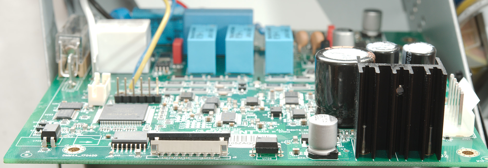
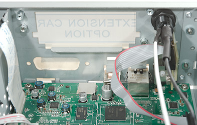
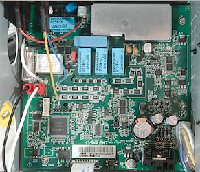
At look down into the electronic section, it has two circuit board. One for the processor and one for the analog stuff.
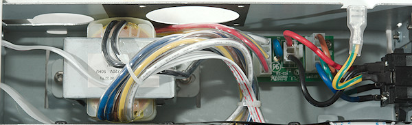
The mains input wires goes to a small circuit board together will all other mains wiring.
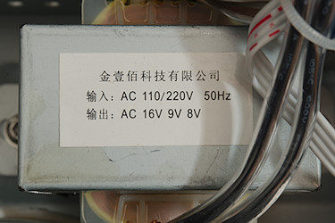
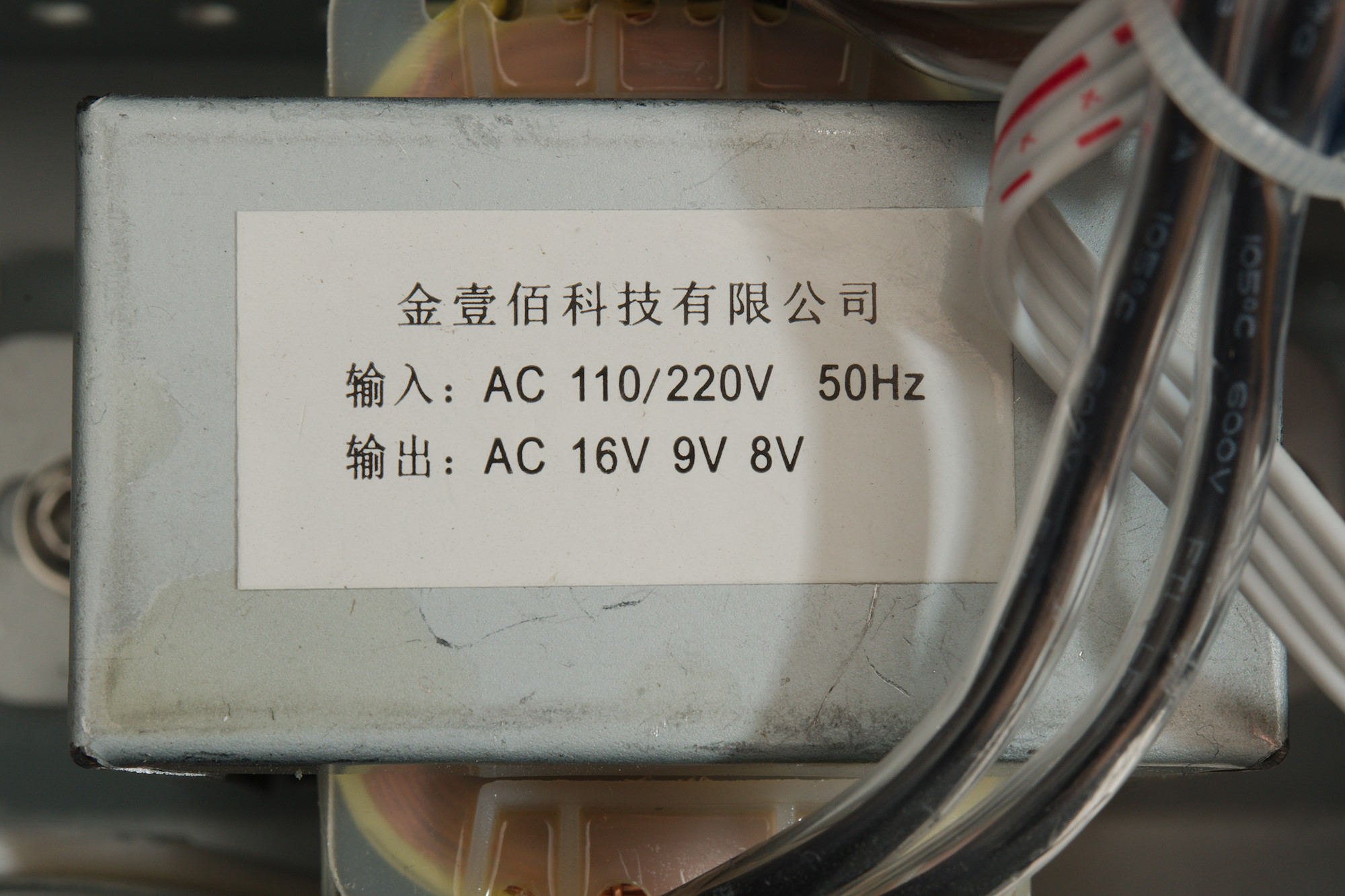
The transformer has 3 output voltages, two for the analog board and one for the processor board.
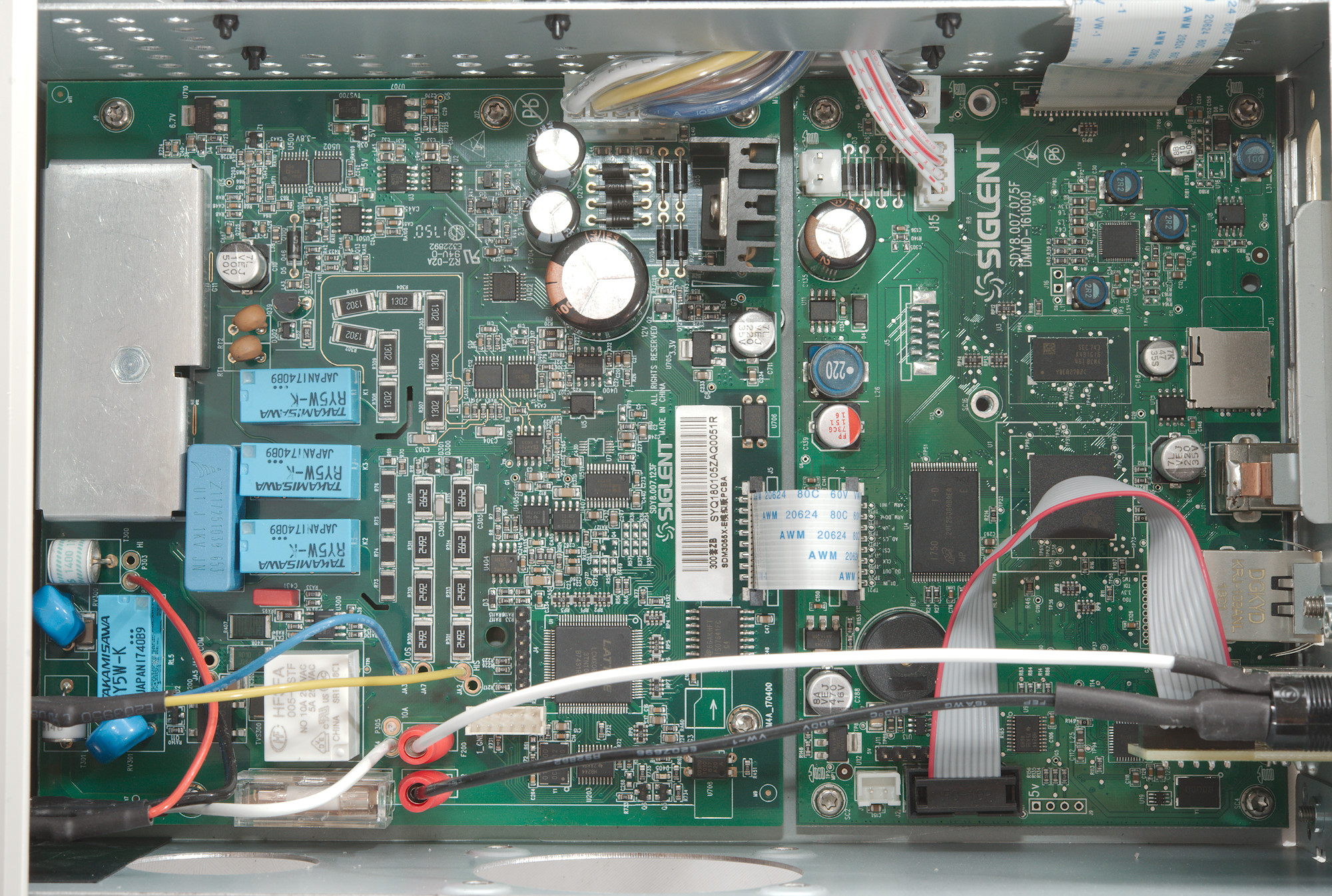
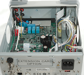
Back and front of the circuit board section. The connections from the front is soldered to the analog board.
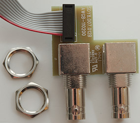

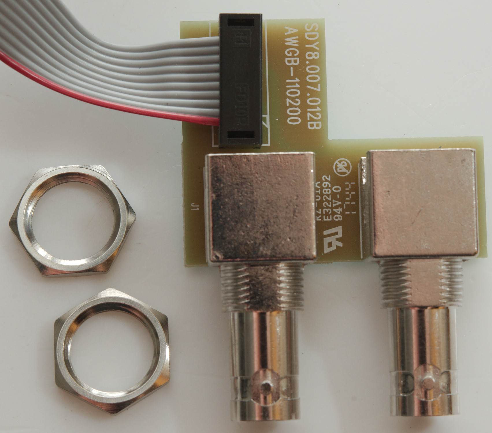
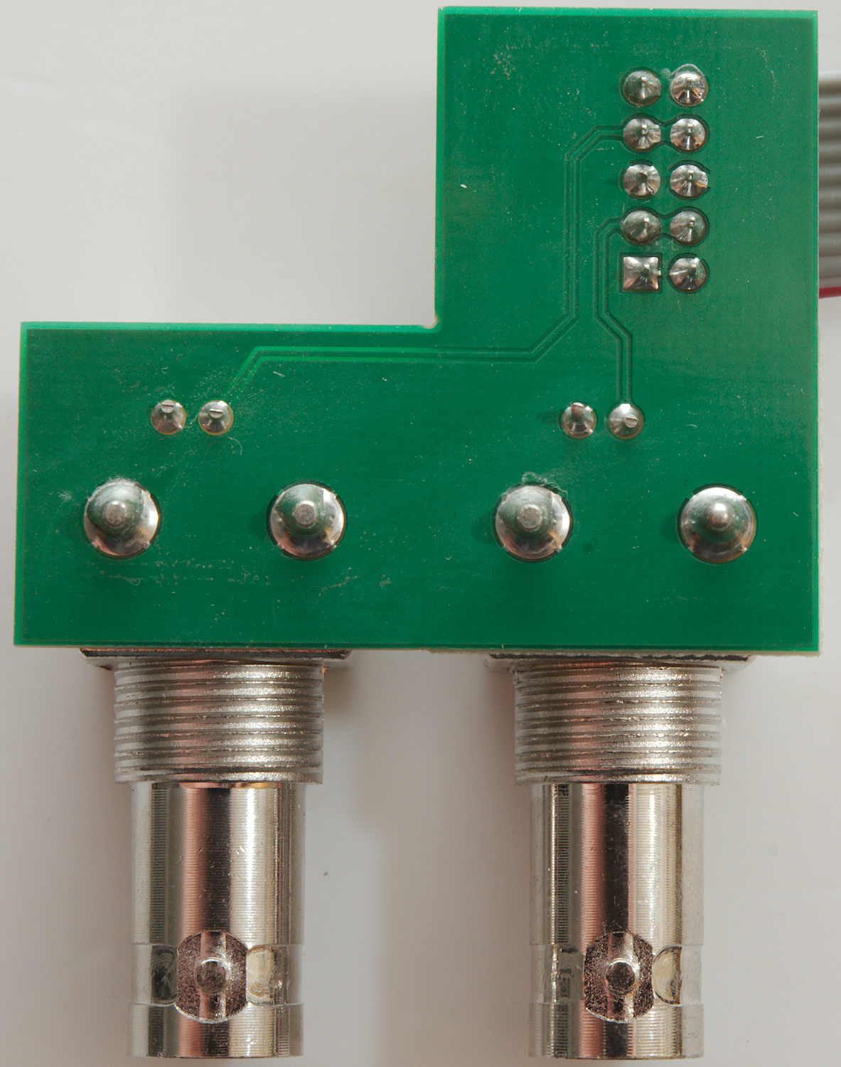
The two BNC on the back share a small circuit board that connects them to a flat cable.
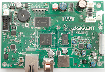
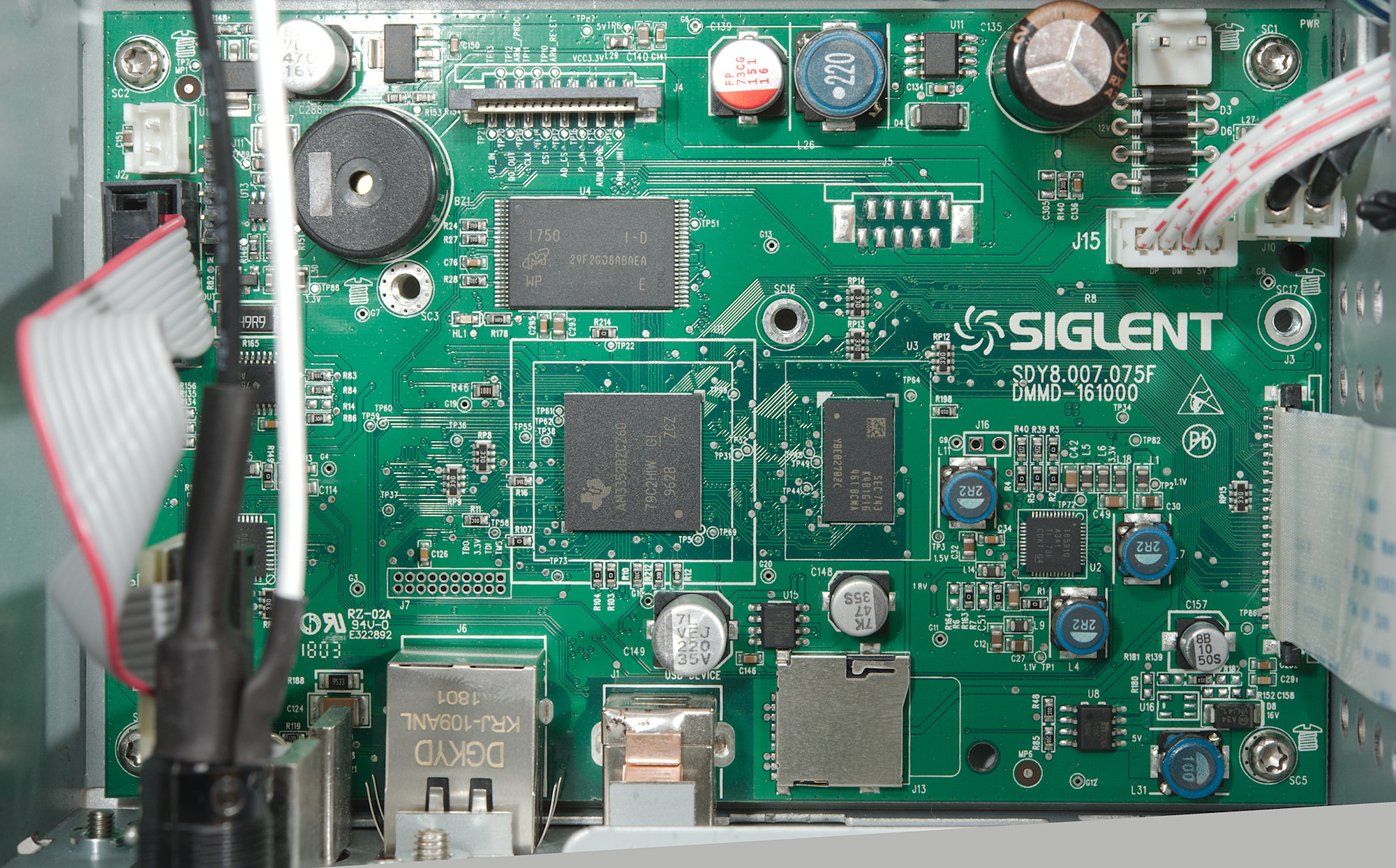
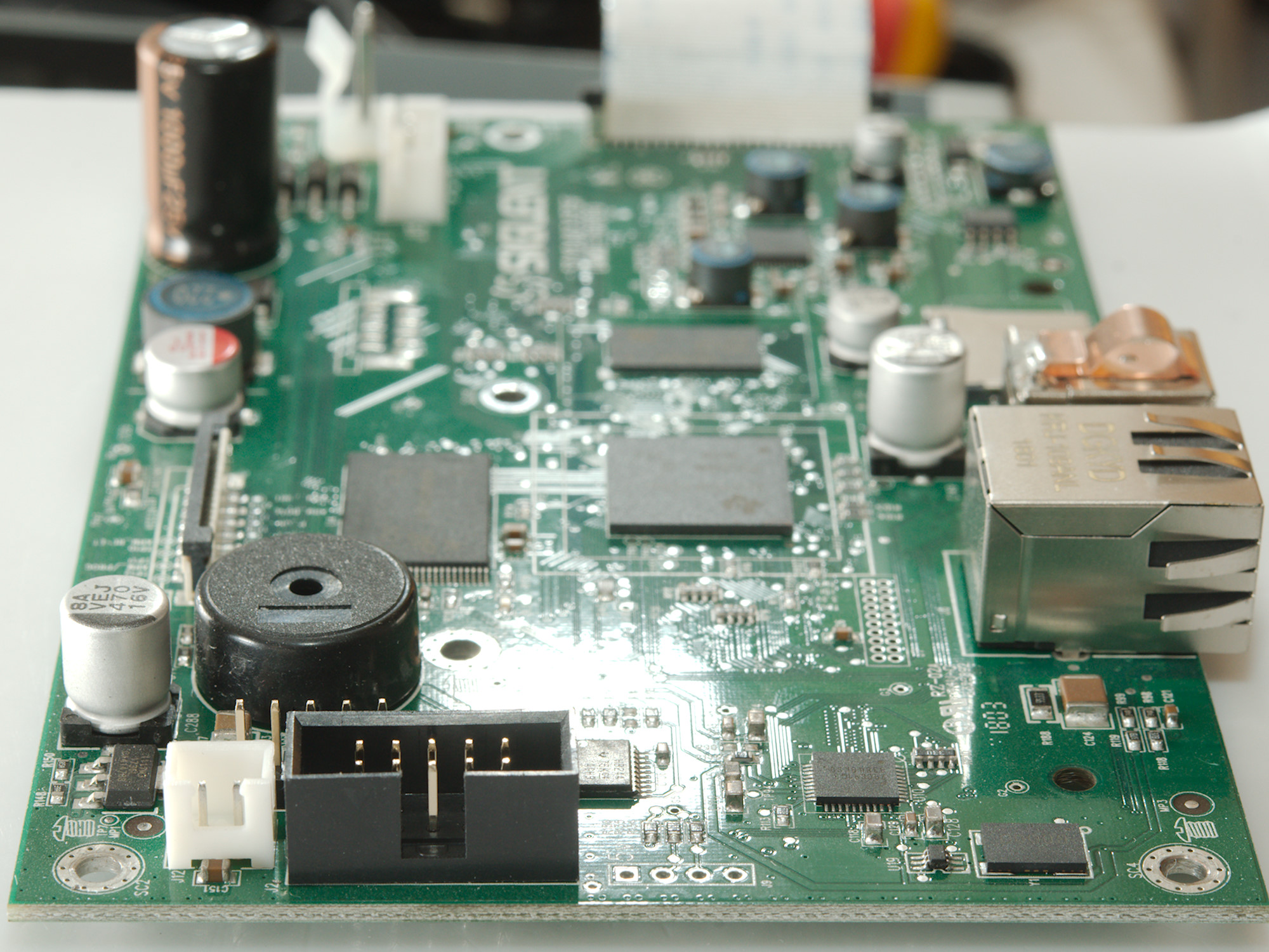
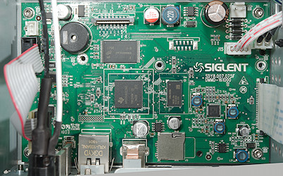
On this board is the processor (U1: AM3352 Arm Cortex A8), some flash memory (U4: MT29F2G08 2GB Flash) and a DDR RAM (U3: Marked SEC743/K481616/46IBCNA/YBE0270ZC) with a bus termination voltage controller (U15: LP2998). The last of the larger chips (U10: Marked 79CC91G3 / 83848KS0) is probably a network interface.
The power supply is a advanced power management chip (U2: TPS65910), a single switcher (U11) and some linear regulators (U12 & U14: L1117).
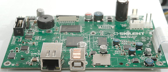
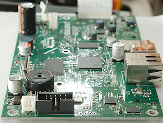


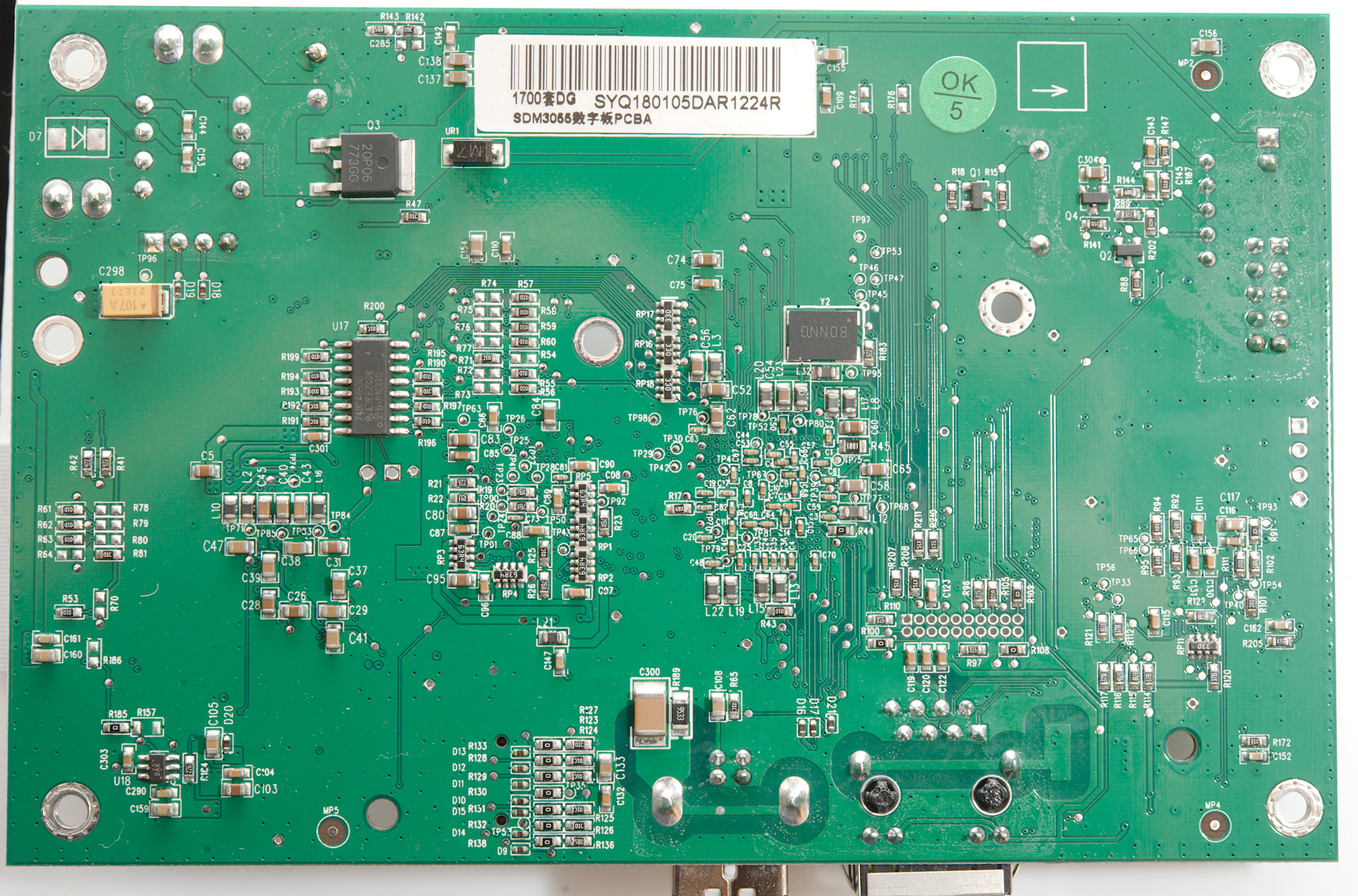
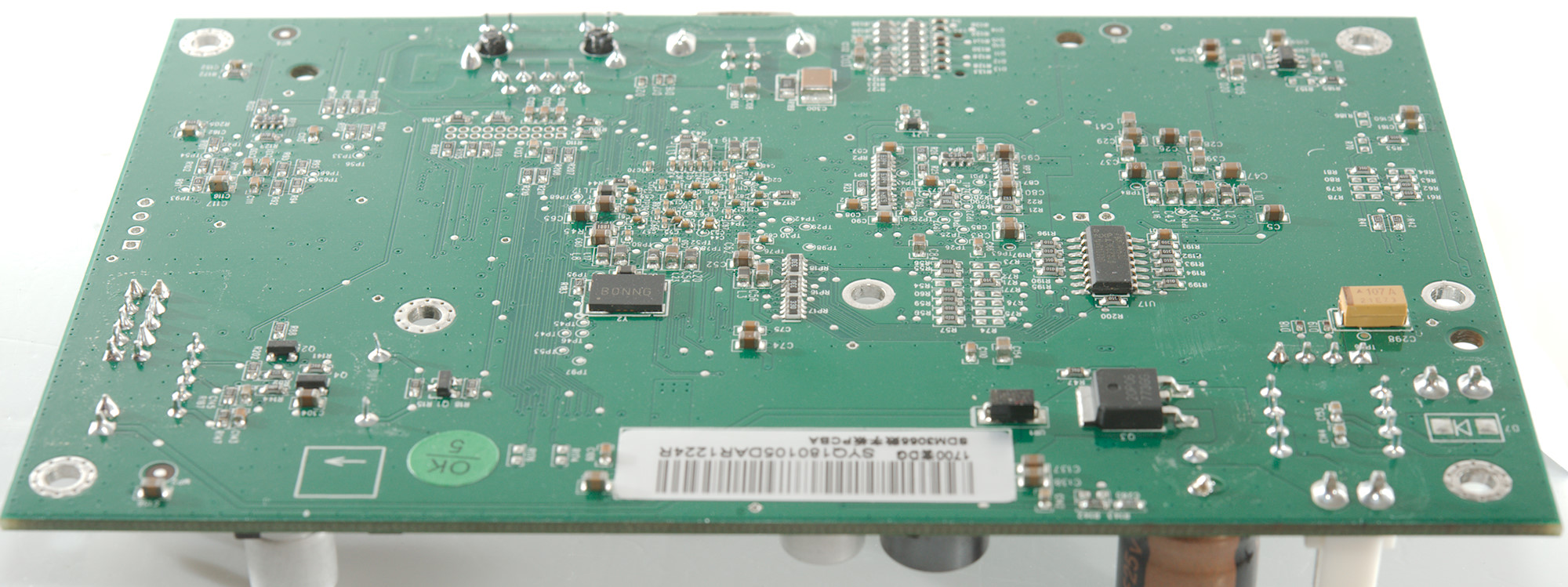
The other side is mostly resistors and capacitors. There is also a large transistor (Q3) to handle the soft power on for the processor board.
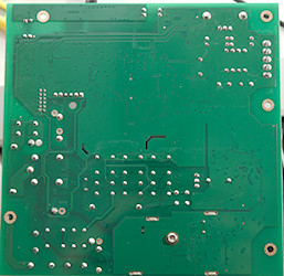
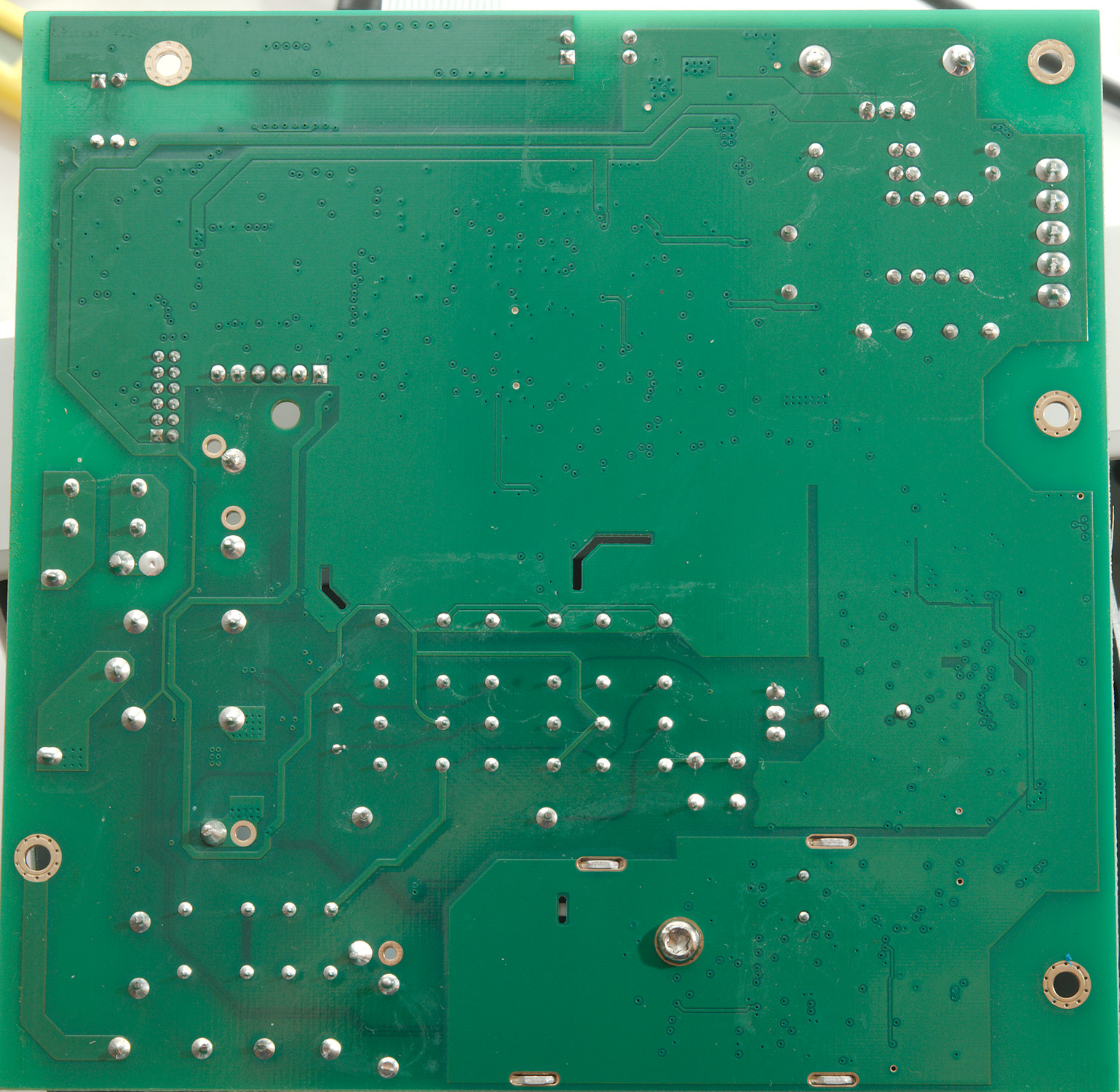
The analog board do not have any components on the bottom.
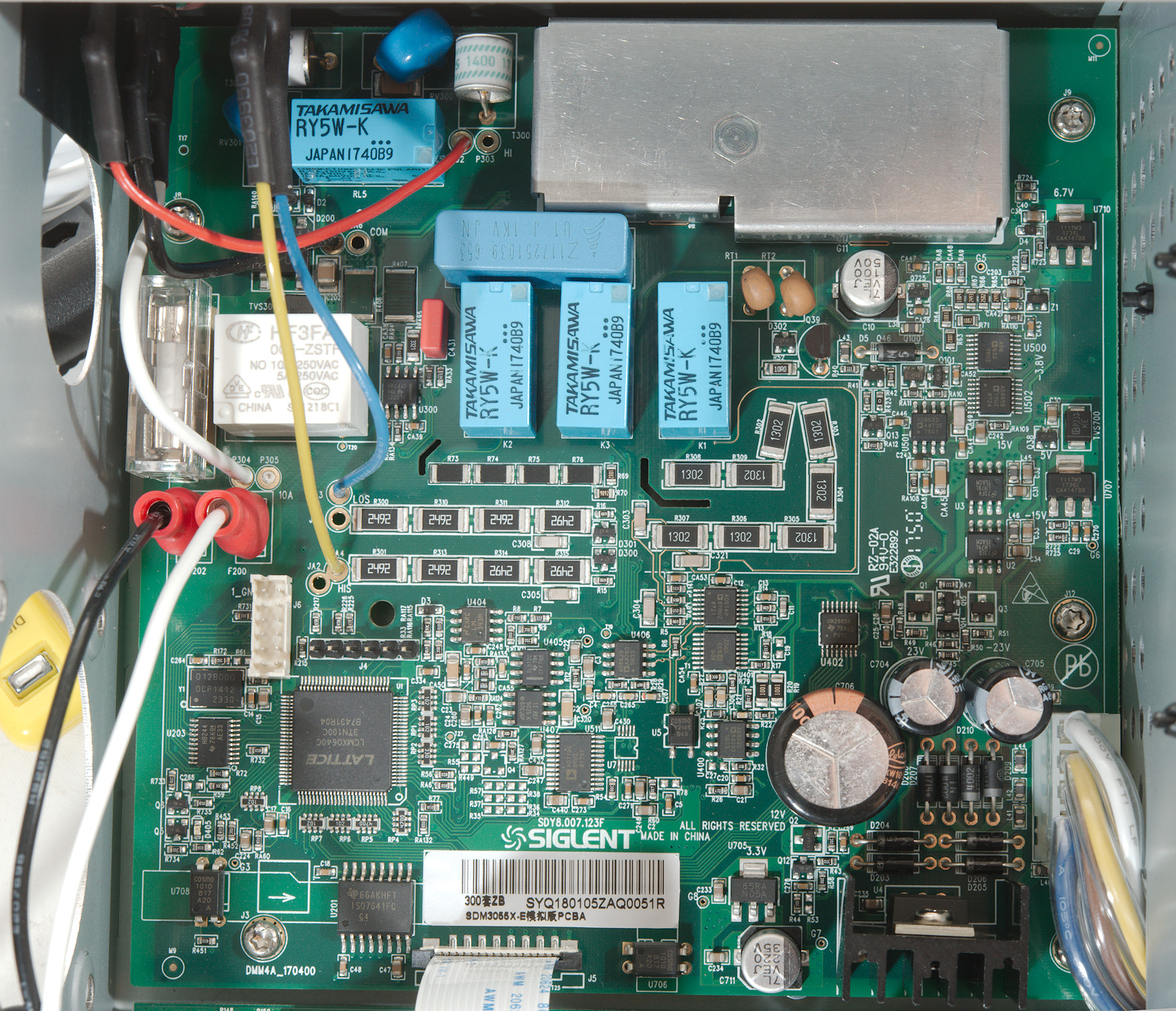
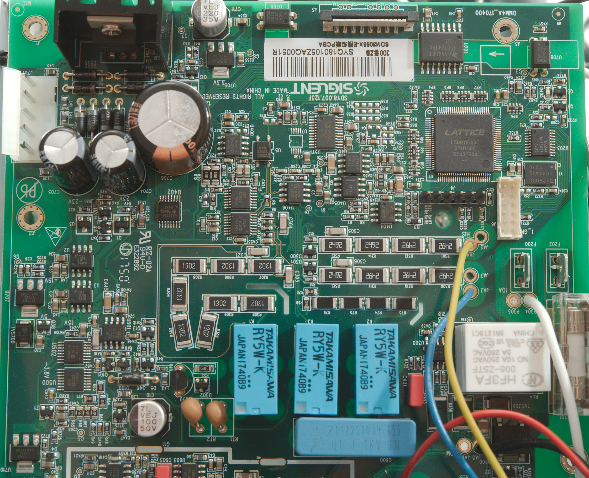
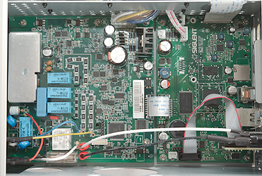
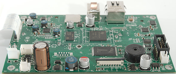
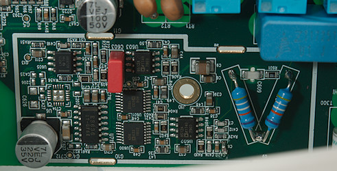
The controller on the analog section is a Lattice PLD (U1: LCMX0640C-3TN100C 640 LUTs & 74 I/Os), it is connected to the processor board with a isolator (U201: ISO7641FC 3000V RMS isolation) and two optocouplers (U706 & U708: Cosmo K1010 5000 V RMS isolation). The analog converter (U511: AD7190 24 bit) is way better than this meter needs, the reference (U407: REF5025K 3ppm/°C) is also very high specification. There is support from some OpAmps and analog switches and +/-15V analog supply (U2 & U3: LM79L15 & LM78L15))
The input resistors are build from many resistors in series. The Sense input has 4 resistors (R301, R313, R314, R315: 4x29.9kOhm & R300, R310, R311, R312: 4x29.9kOhm) with diodes at the end (D300 & D301) for each terminal. There is also a 100kOhm input chain (R302, R303, R304, R305, R306, R307, R308, R309: 8x13K), the reason for that many resistors is probably power handling during overload and a 10Mohm chain (R73, R74, R75, R76>: 4x2.5Mohm).
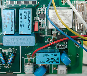
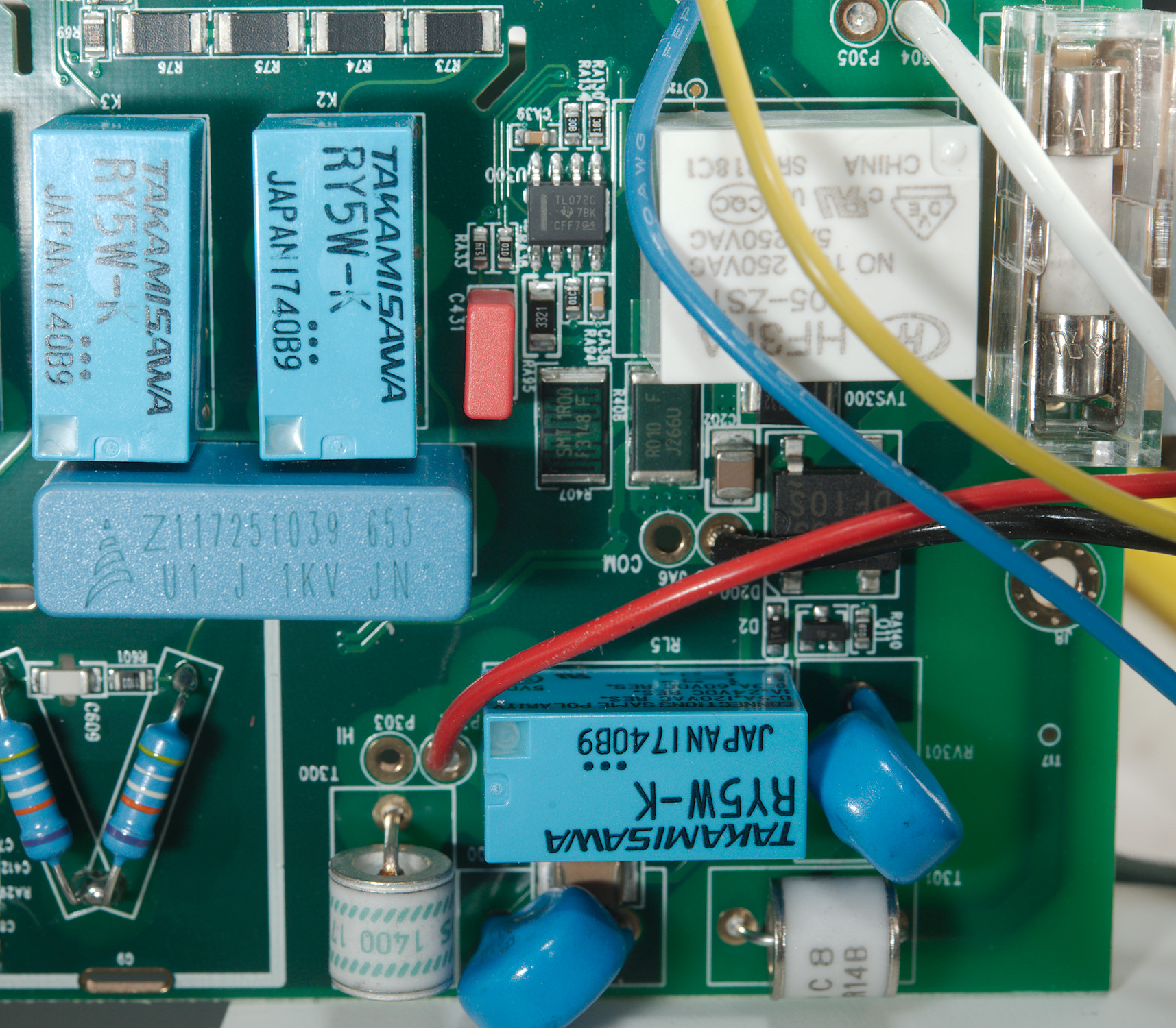
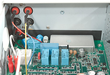
The input area has 5 mechanical relays for range selection. Below the white relay is the current shunts for 10A (R408: 0.01ohm) and uA/mA (R407: 1ohm) and a OpAmp (U300: TL072C). There is also the 1000 volt input capacitor, two MOVs and two spark gaps.
In addition to the fuse on the backside there is another one here, it is ceramic, but not a high voltage HRC fuse.
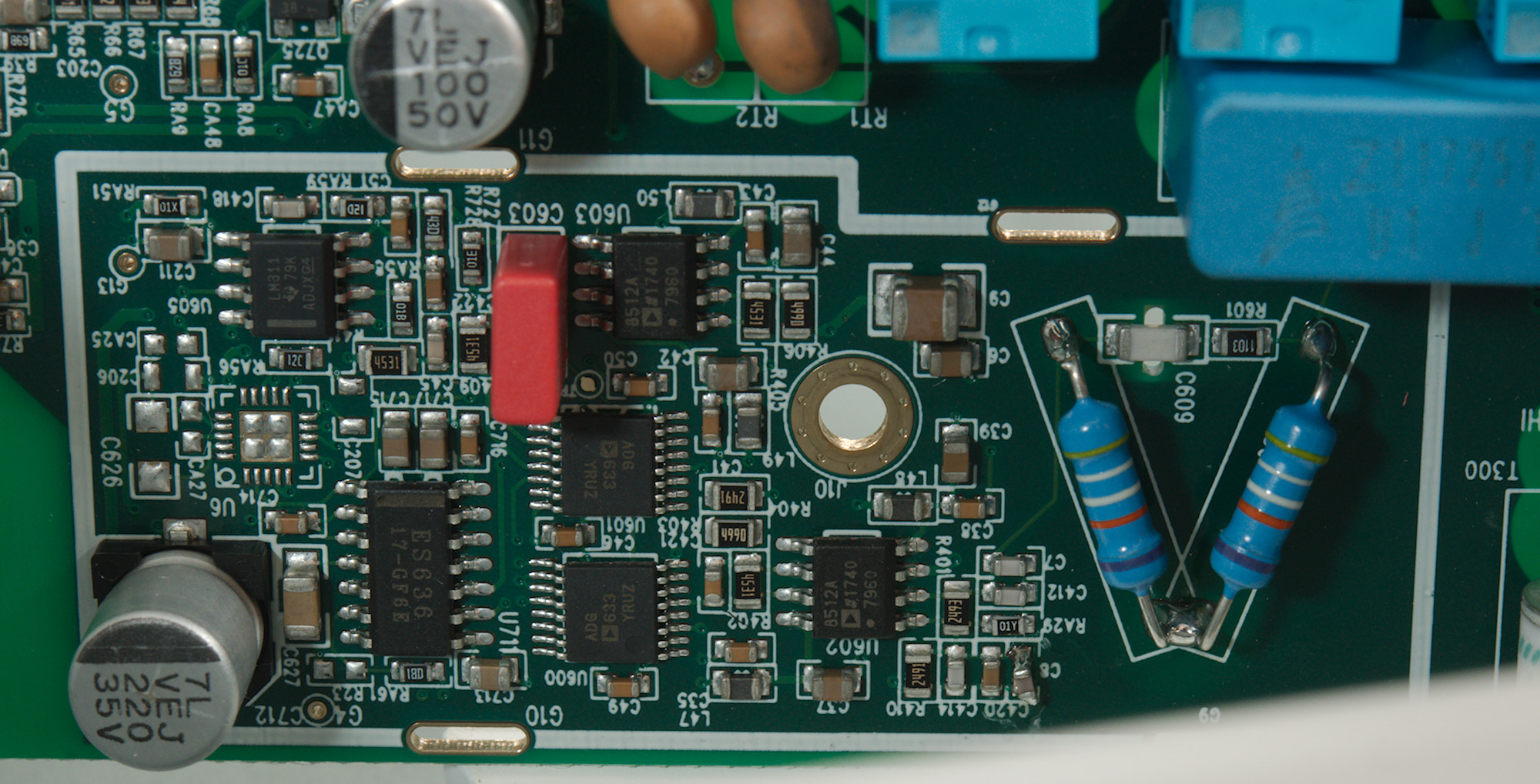
Below the metal shield is OpAmps, analog switches and the RMS converter (U711: ES636 0.1%)
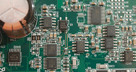
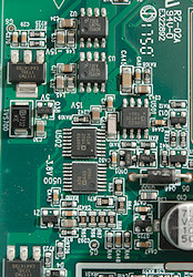
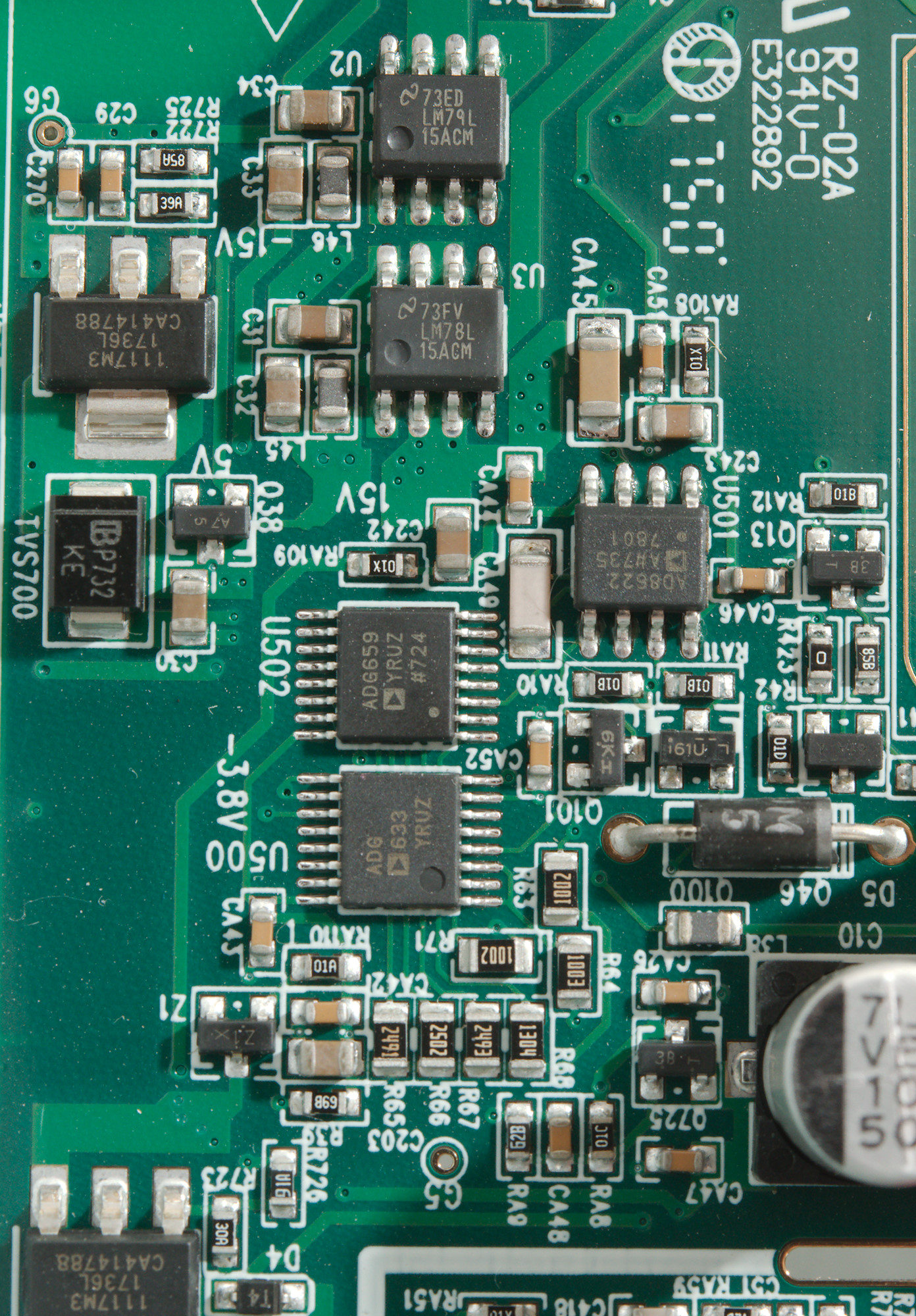
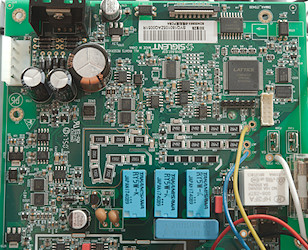
Zoom in on part of the analog board, all IC numbers can be read here.
Conclusion
This is not a top end bench meter with "only" 4½ digit, but the meter works the same way as they do, with user interface, communication, relays/analog switches to handle all range changes. This meter is not a handheld meter with a mains power supply build in, but a real bench meter.
Generally the meter works exactly has expected, that means fairly good. I like that the current input is auto ranging from uA to A. The support for thermocouples is not present in all bench meters, but here it is, together with a minimum PT100 support (It is missing 3 & 4 wire support).
The software is good for a multimeter software and that it is free makes it even better.
I believe you get a lot of bench meter for the money with this meter, especially if you want to use the computer connection.
Notes
Siglent has 3 meters in this series:
SDM3045X: 4½ digit
SDM3055X: 5½ digit
SDM3065X: 6½ digit, can be ordered with a build in multiplexer.
The layout and user interface is very similar to Keysight meters
How do I review a DMM
More DMM reviews