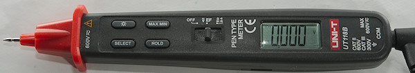
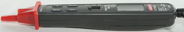
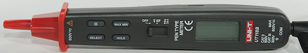
DMM UNI-T UT118B
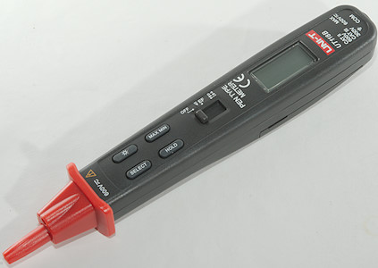
This is a small pen DMM with voltage, ohms and capacitance.
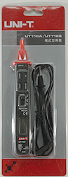
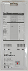
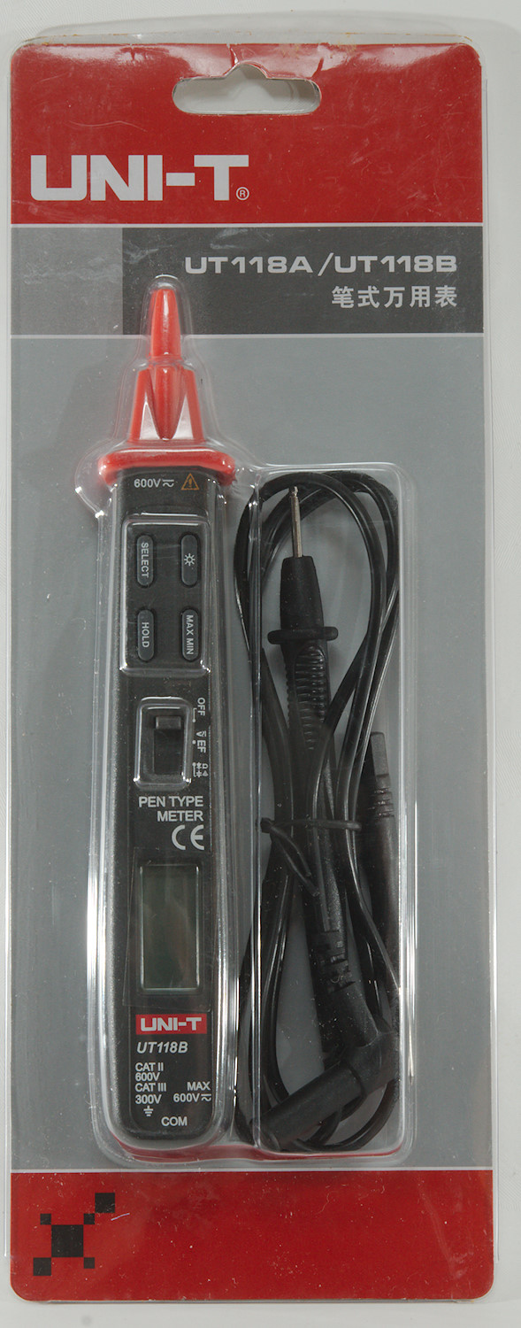
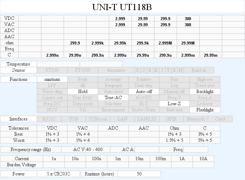
The meter was in a clamshell pack. On the back is a comparison between the 2 models in this series, only difference is NCV.
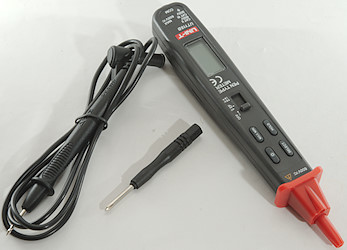
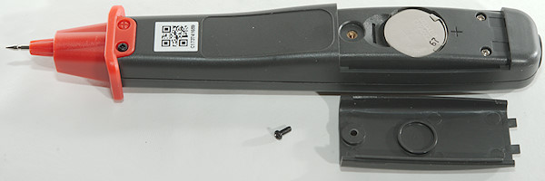
In the pack was the meter, a probe, a screwdriver and a manual in English.
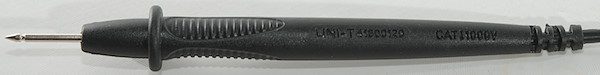
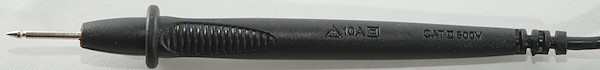
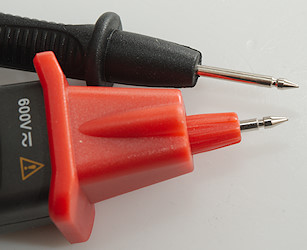
The probes is standard size and rated for much more than the meter.
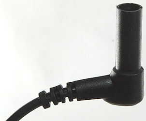
The shroud is standard size.
And plugs into the back of the meter.
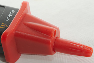
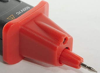
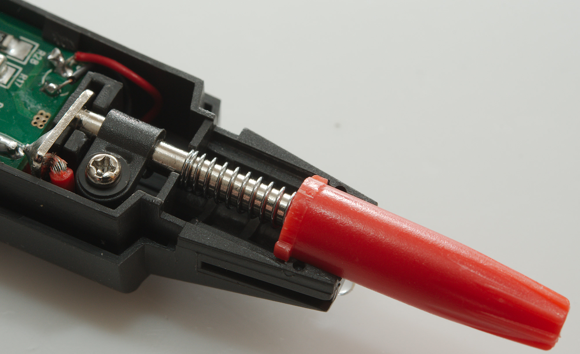
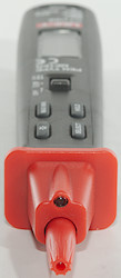
The tip has a cover that can be locked in retracted position by turning it. There is also a led near the tip to illuminate the area where the measurement is performed, but it is not very bright.
Display
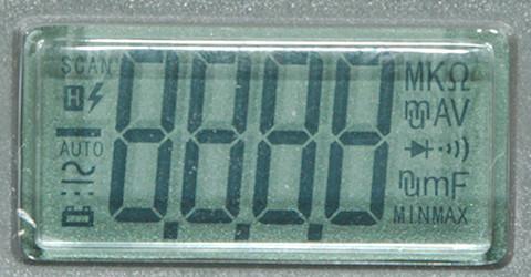
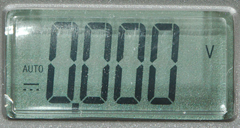
The above picture shows all the segments on the display.
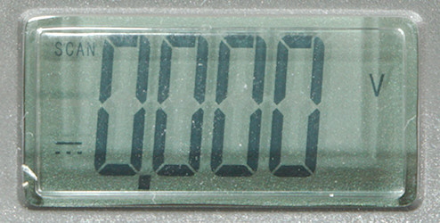
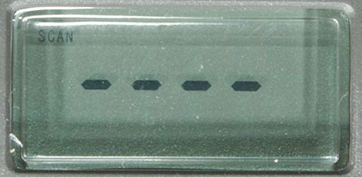
Automatic mode in voltage, it will switch to AC or DC as needed. It is the word "SCAN" that means it is searching for mode.
Here I have manually selected DC voltage, "SCAN" disappers and "AUTO" means automatic range.
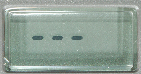
Automatic scan in ohm, diode, continuity and capacitance mode.
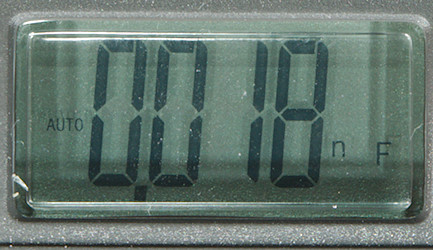
Manual selection of capacitance.
NCV or Electric field mode uses display and buzzer to signal that a field is detected.
Functions
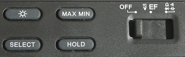
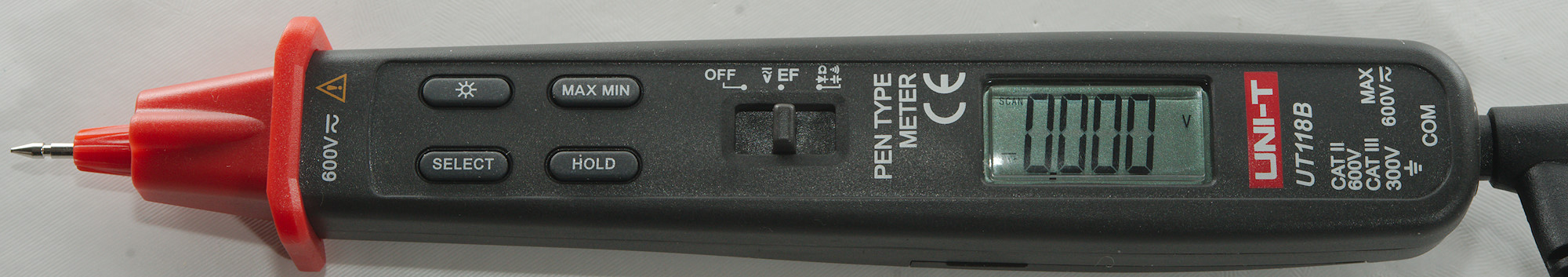
Buttons:
 : Turn background and flashlight on with a press.
- Max min: Capture maximum and minimum values, it can show max/min/minmax(actual value), hold down to disable.
- Select: Will select between Auto(SCAN) and the available ranges.
- Hold: Will freeze the display reading, until pressed again.
Selection of max min will disable auto ranging
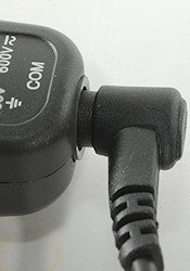
Slide switch:
- Off: Meter is turned off
- V EF: DC/AC voltage and electric field detection.
 : Ohm, diode continuity and capacitance.
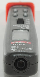
Input
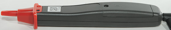
This meter has the red probe build in, the black probe is connected at the back.
Measurements
- Volt and frequency
- 1V AC readings is 5% down at 2.3kHz
- V input impedance is 10-11Mohm below 8V and dropping to 100kOhm above.
- There is an audible alarm when voltage is above range.
- Max/min can capture a voltage in about 180mS.
- It is recommended never to never exceed 300V AC/DC input voltage.
- Current
- Meter cannot measure current.
- Ohm, continuity, diode and capacitance
- Ohm needs about 0.8s to measure 100ohm
- Ohm is -0.73V open and -0.65mA shorted (Voltage is reversed)
- Continuity is very fast (<5ms)
- Continuity beeps when resistance is below 25ohm
- Continuity is -1.24V open and 0.62mA shorted
- Diode range uses 2.7V, max. display is 1.999V at 0.5mA, max. current is 1.68mA shorted
- 10000uF takes about 6 seconds to measure.
- 10uF takes about 1 seconds to measure.
- Auto scan works fine and fairly fast, but there is some limits on the values it will handle.
- Rated overload protection is 300 VDC/VAC
- Miscellaneous
- Current consumption of meter is 3mA (9mA with backlight and flashlight on).
- Meter turns off below 1.6V, battery symbol show at 2.3V.
- Readings will not drift with battery voltage.
- Display is very small and viewing angle is restricted by mechanical construction. LCD also has a dead spot when viewed from the top.
- Display updates around 3 times/sec
- Will automatic turn power off after about 10 minutes
- Backlight will turn of in about 60 seconds.
- Flashlight follows backlight, turn on and off at the same time.
- The meter often need many display update to reach the final value.
- Weight is 64g without accessories, but with battery.
- Size is 180 x 28 x 22mm (Minus probe not included).
- Probes
- Probe wire has about 76mOhm in resistance.
- Probe wire is 89cm long.
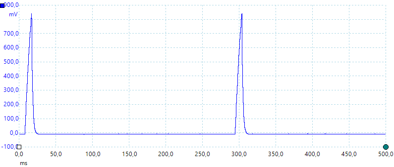
capacitance measurement waveform.
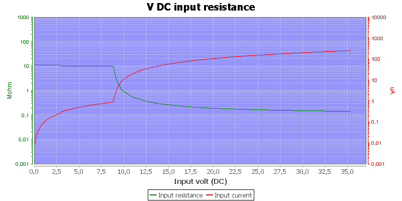
The specifications says 10Mohm, but that is only at low voltage.
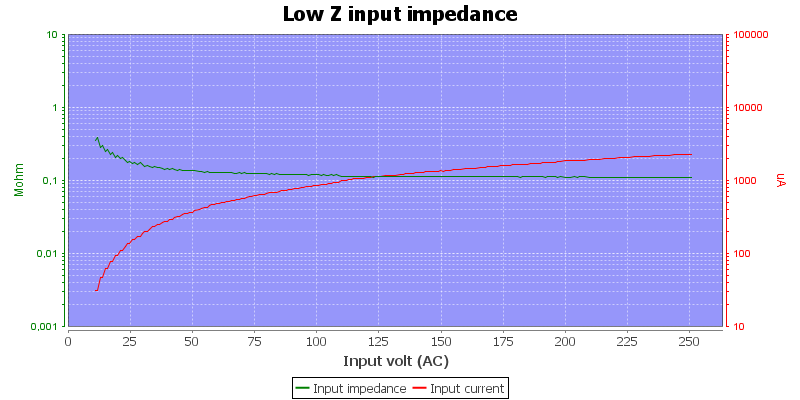
I will rate this input as a LowZ input.
For good precision on low capacitance values, the residual reading must be manually subtracted (There is no REL mode). The meter support capacitance ranges at least up to 30mF, but the precision is non-existent in these ranges (Specifications only goes up to 300uF).
The LowZ is not optional see curve with input impedance.
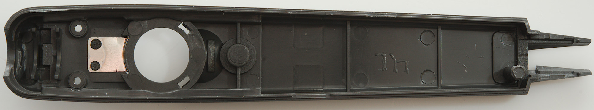
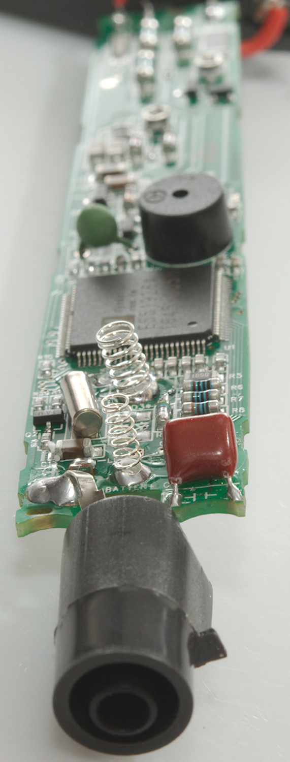
Tear down
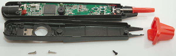
I had to remove 3 screws, before I could open it up.
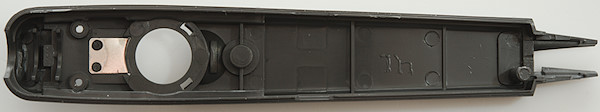
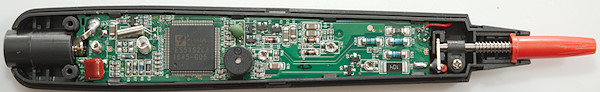
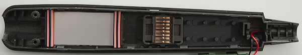
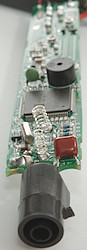
There is some mechanical construction around the front and the back to support the inputs.
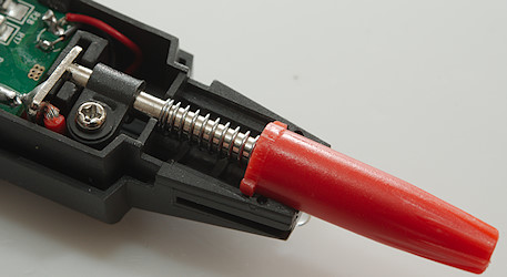
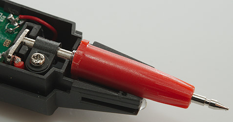
Tip retracted and out.
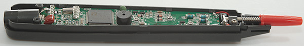
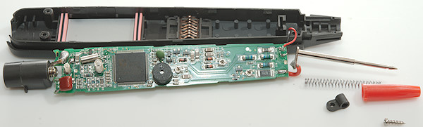
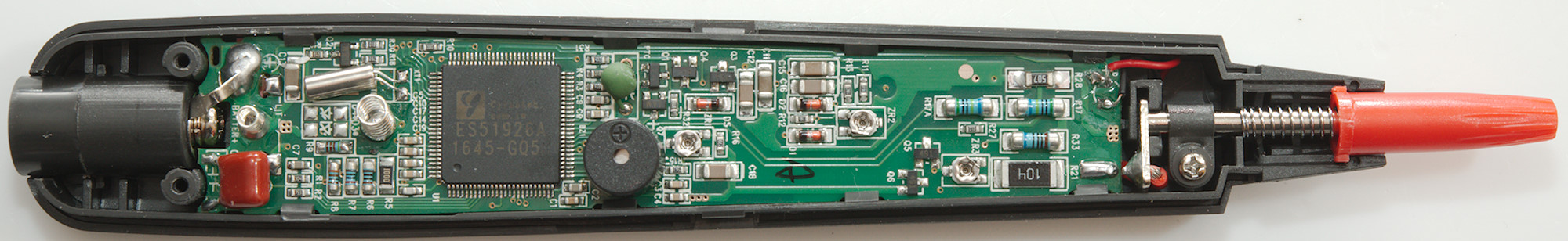
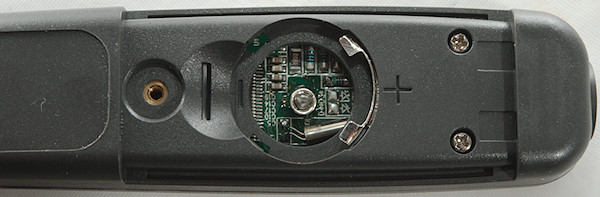
The circuit board was mounted with clips, the only screw was holding the tip.
The two wires are for the flashlight in front.
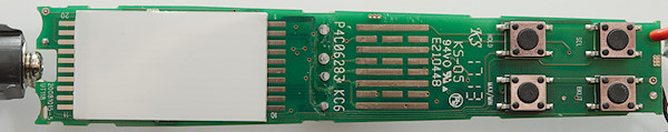
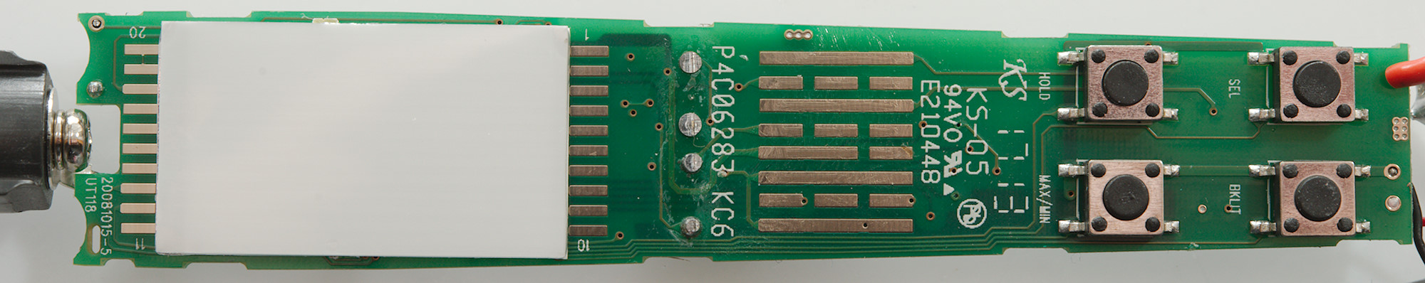
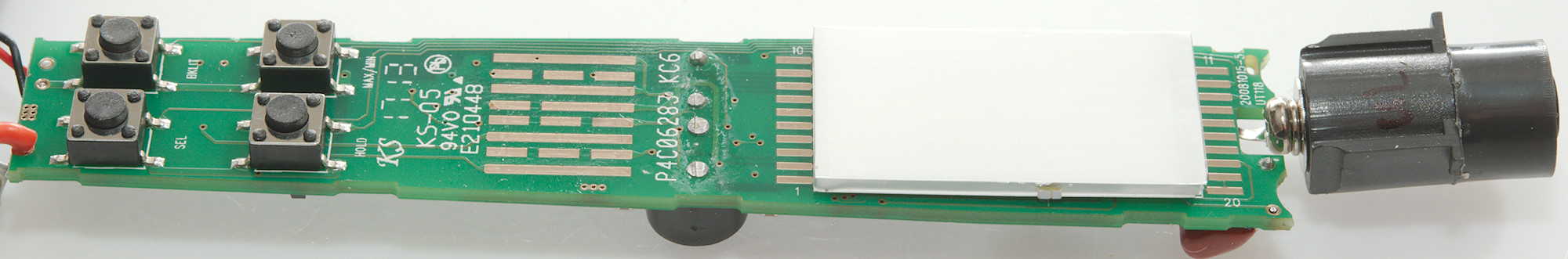
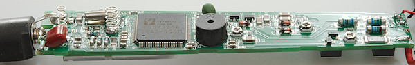
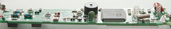
This side has the connection for the LCD zebra stribe, the backlight (White area), the range switch and four buttons
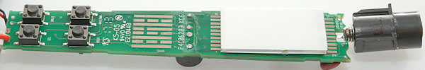
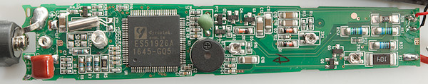
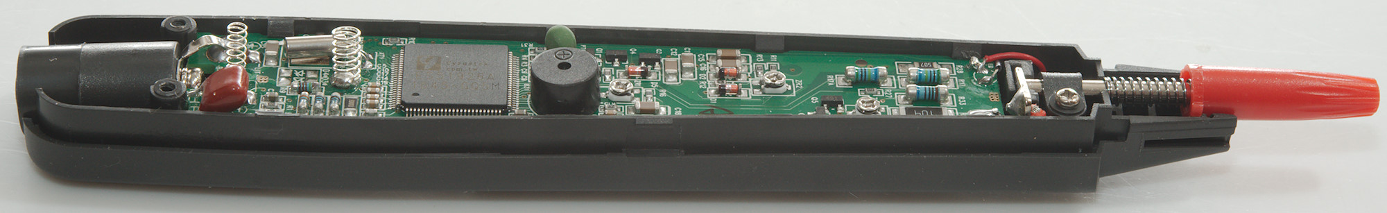
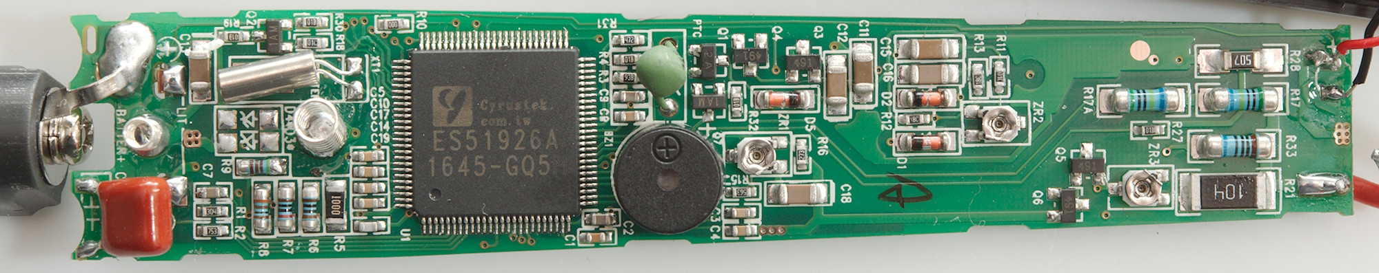
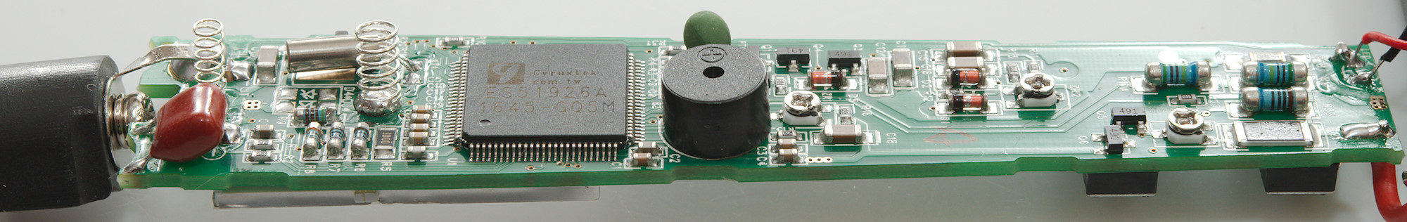
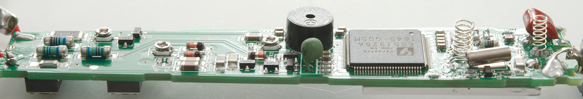
At the input there are 3 paths: High impedance (R17 & R17A: 2x5Mohm), low impedance (R33: 100ohm), medium impedance (R21: 100kOhm), the medium impedance has a trimpot in series (ZR3: 5.9kOhm) and a transistor pair for protection (Q5 & Q6), this path is used for input during ohm, diode and capacitance. This pair is always connected and keeps the input impedance down at higher voltages. The diodes (D1 & D2) and other parts near ZR2 is the rectifier for the AC ranges.
There is a PTC and a protection pair (PTC, Q3 & Q4) near the multimeter chip, this is for the ohm, diode and capacitance ranges.
The multimeter chip (U1: ES51926A 3000 count) is designed for automtic mode selection.
Conclusion
The meter says CAT II 600V, but the manual says to stay below 300V, I do not believe the rating (CAT II 600 is up to 4000V).
The number of functions in the meter is fairly limited, but it is fast to measure. The (unintentional) Low-Z can be useful for checking mains.
Notes
How do I review a DMM
More DMM reviews