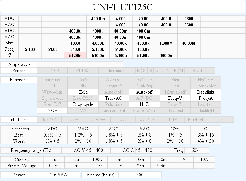
DMM UNI-T UT125C
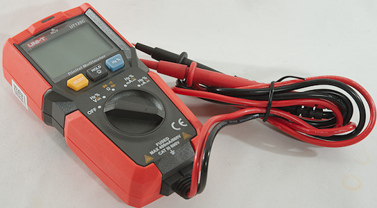
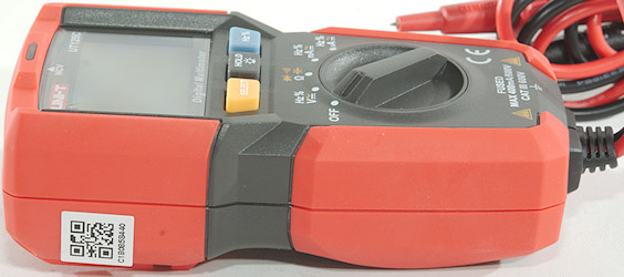
Uni-T has a large selection of DMM in their program, this model is a compact meter with build in probes and a broad selection of ranges.
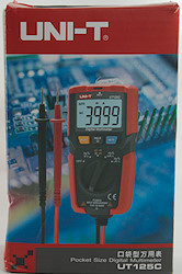
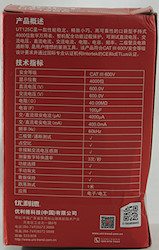
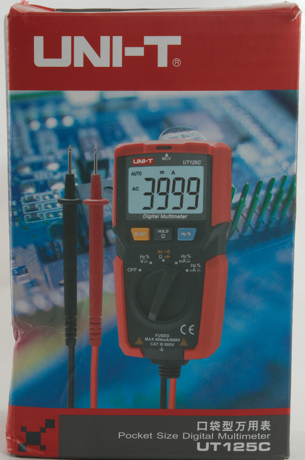
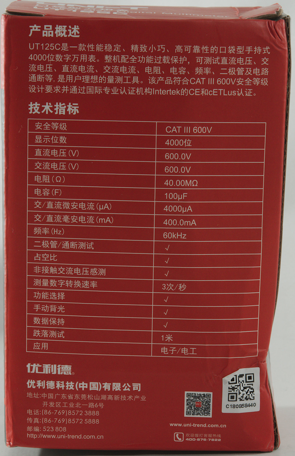
The meter arrived in a red box with Chinese writing.
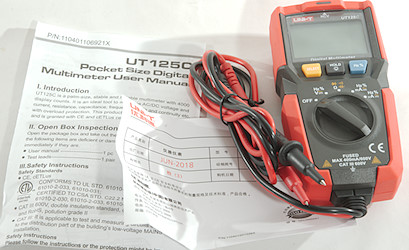
The box contained the meter and a instruction sheet in English.
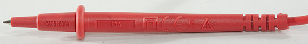
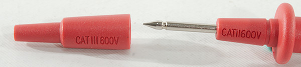
The probes are rated for 600V and CAT II or CATII depending on if tip cover is used.
The meter is fairly light weight and you have to press on it or use two hands to rotate the switch.
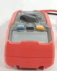
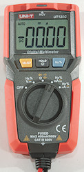
Display
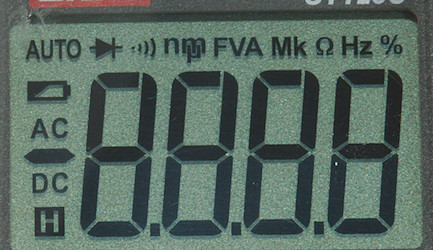
The above picture shows all the segments on the display.
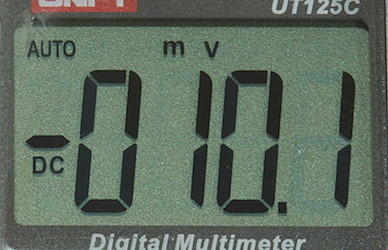
Typical display during usage, it will show the number and what measurement is selected.
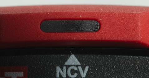
The electric field detection (NCV) is a red led at the top of the display, if the meter is on it will light up when a field is detected, there is no sound or display indication. This detector is very sensitive and the indicator turned on very frequently.
Functions
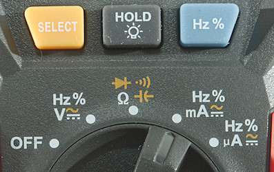
Buttons:
- Select (Yellow): Selects the ranges printed with yellow on the rotary switch.
- Hold: Will freeze the display, hold down to turn on background light
- Hz % (Blue): Select Hz and duty cycle display, works both in voltage and current ranges.
Using the Hz % button will disable auto range.
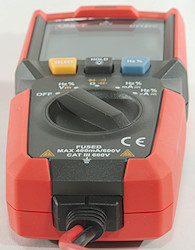
Rotary switch:
- Off: Meter is turned off
- V: Show DC and AC voltage, use Select for AC and "Hz %" for frequency an duty cycle.
- ohm: Resistance, diode, continuity and capacitance.
- mA: Current DC and AC, use Select for AC and "Hz %" for frequency an duty cycle.
- uA: Current DC and AC, use Select for AC and "Hz %" for frequency an duty cycle.
Input
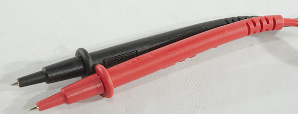
This meter only have a red and black probe coming out, no other connections.
Measurements
- Volt and frequency
- Frequency input requires a zero crossing.
- At 0.1Vrms frequency input range is from 0.8Hz to 6kHz
- At 1Vrms frequency input range is from 0.6Hz to 26kHz in mV range (Increasing voltage to 5Vrms only increased range to 30kHz).
- At 5Vrms frequency input range is from 0.6Hz to 100kHz in VAC range
- Duty cycle works from 10% to above 90% at 3kHz with 1Vpp, precision is within 2.4.
- 1 VAC is 5% down at 2kHz
- Input impedance is 10-11Mohm on DC and AC
- Input impedance is high on mV DC range up to about 1.8V where it drops to 10Mohm
- Frequency input impedance is the same as the range it is selected in.
- NCV is very sensitive and triggers on a lot of stuff.
- Voltage ranges are rated for 600V DC/AC input.
- Current
- mAuA range is protected with a 0.5A/660V 6.3x32mm fuse
- Ohm, Continuity, diode and capacitance
- Ohm needs about 5s to measure 100ohm
- Ohm is 0.44V open and 0.17mA shorted
- Continuity is moderate in speed (About 80ms).
- Continuity beeps when resistance is below 40ohm, but there is noise up to about 60ohm
- Continuity is 0.44V open and 0.17mA shorted
- Diode range uses 1.5V, max. display is 0.999V at 0.19mA, max. current is 0.55mA shorted
- 10uF takes about 3.8 seconds to measure.
- 100uF takes about 18 seconds to measure.
- Ranges are rated for 600V DC/AC input.
- Miscellaneous
- Current consumption of meter is 1.3mA to 2mA (NCV led adds about 1.2mA and backlight adds 3.4mA, maximum is about 5.4mA)
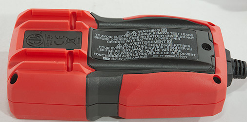
- Meter works down to 1.3V where it turns off, display starts to fade at 1.5V, battery symbol show at 2.4V.
- Backlight varies with battery voltage and is very weak at 2.7V
- Display reading will change below 2.0V and is about 15% low at 1.5V
- The meter usual need a couple of display update to reach the final value.
- Viewing angle is good
- Display updates around 3 times/sec
- Will automatic turn power off in a little above 30 minutes
- Backlight will not turn off automatic, but is turned off when the meter automatically turns off.
- Weight is 170g without accessories, but with batteries.
- Size is 126 x 57.8 x 38mm including strain relief.
- Probes
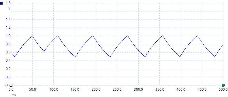
A look at the capacitance measurement waveform.
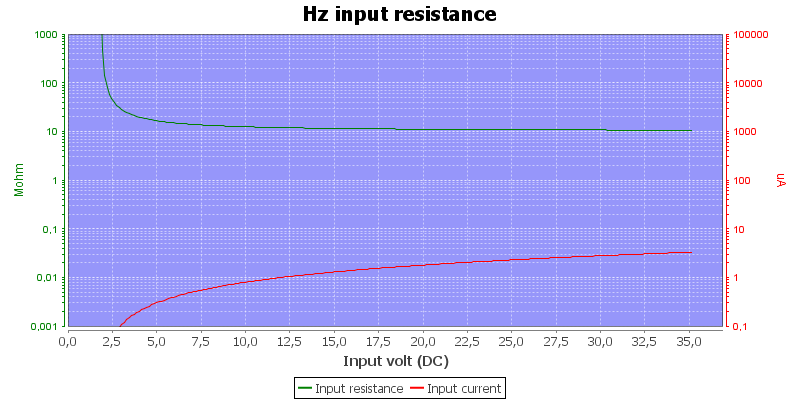
Frequency input impedance depends on voltage, here I selected frequency in mVDC
Capacitance has a 0.25nF (Specifications says offset can be up to 11.00nF) offset and shows 1nF as 1.6nF, you must then manually subtract offset.
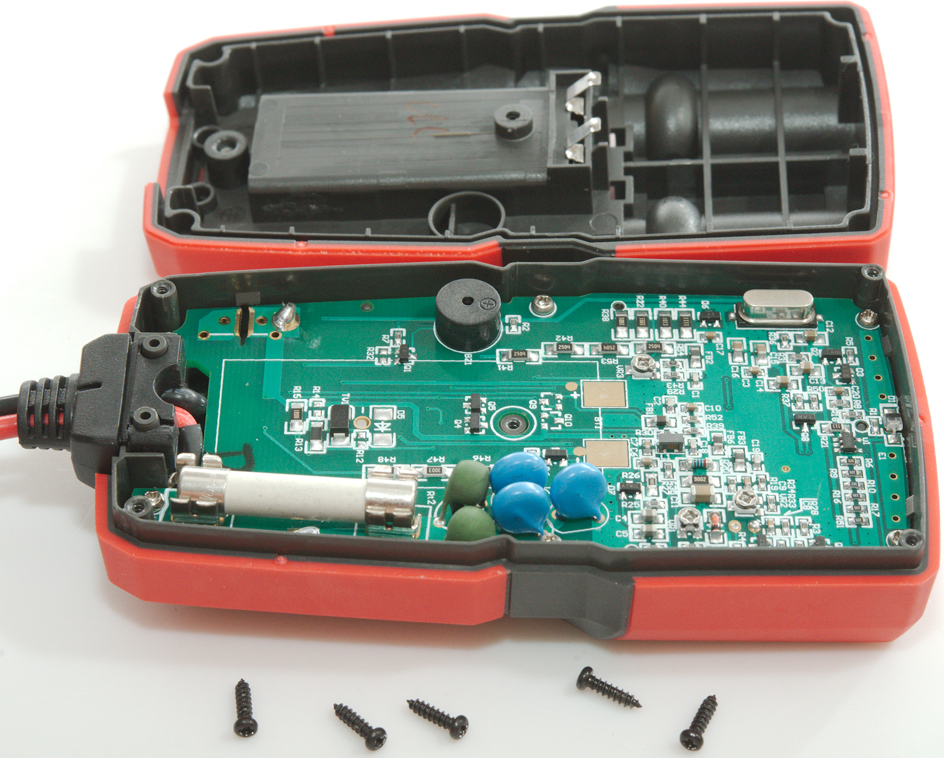
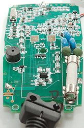
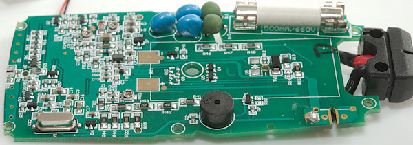
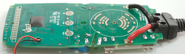
Tear down
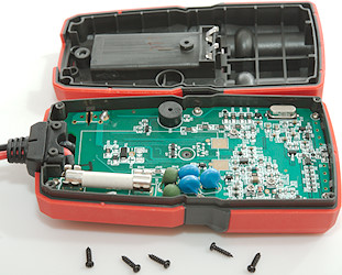
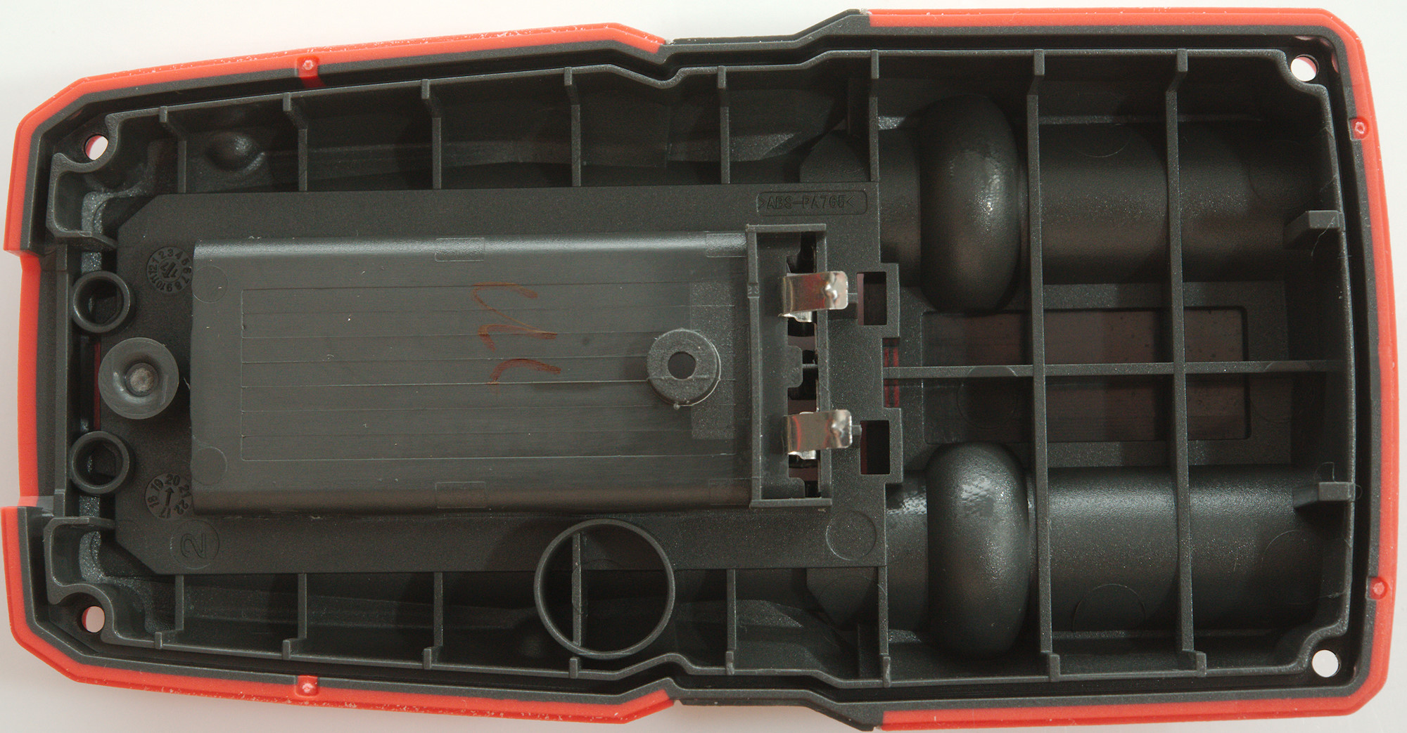
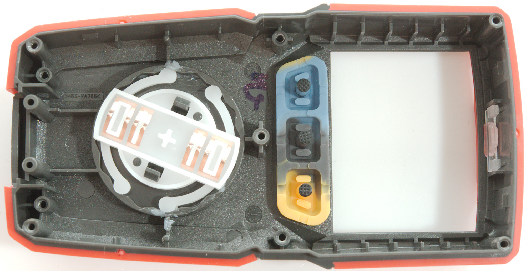
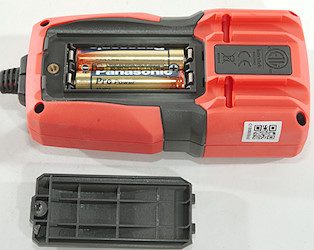
5 screws (One was in the battery box) and the back could be removed.

As usual the circuit board is made to fit the box.
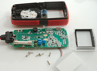
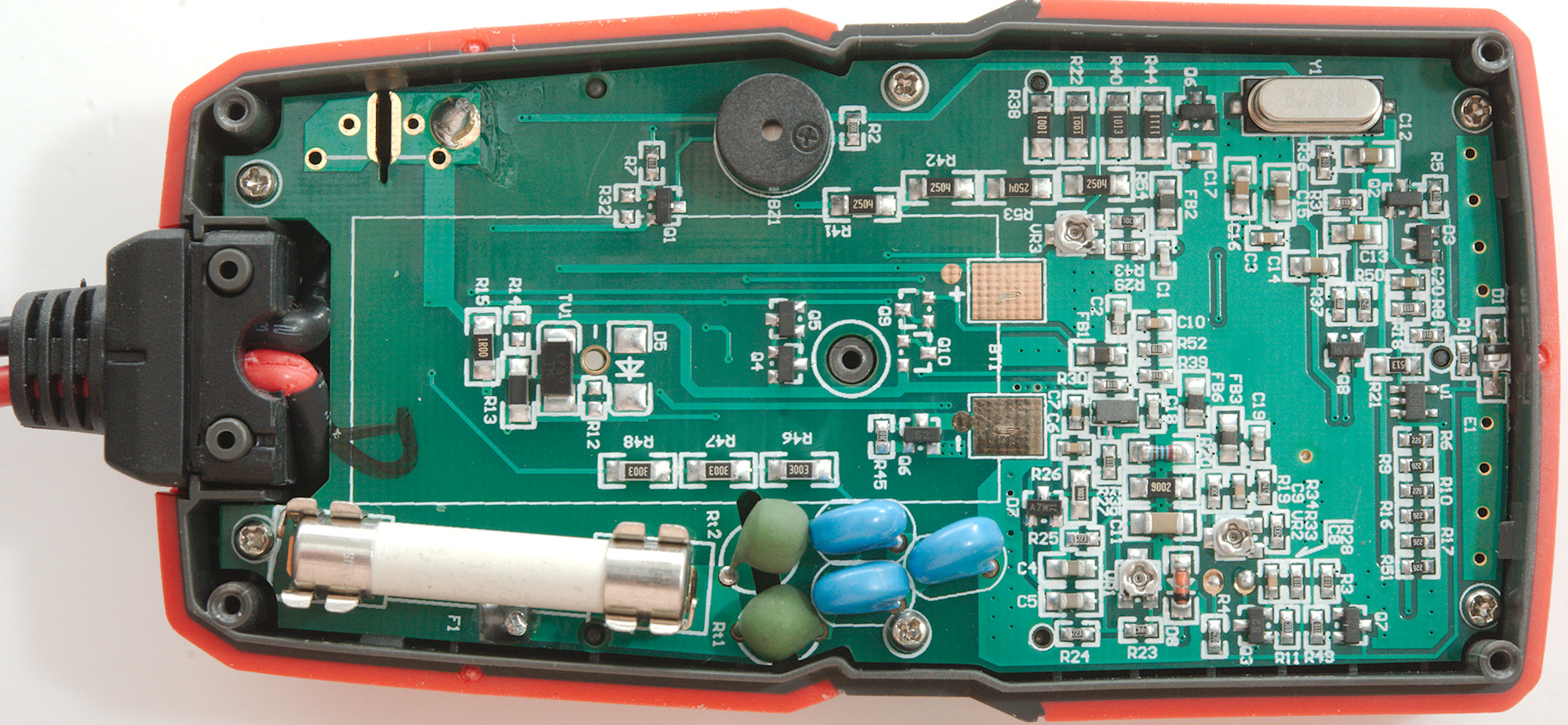
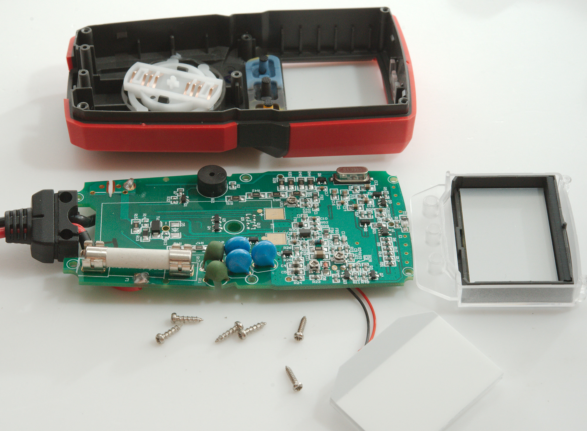
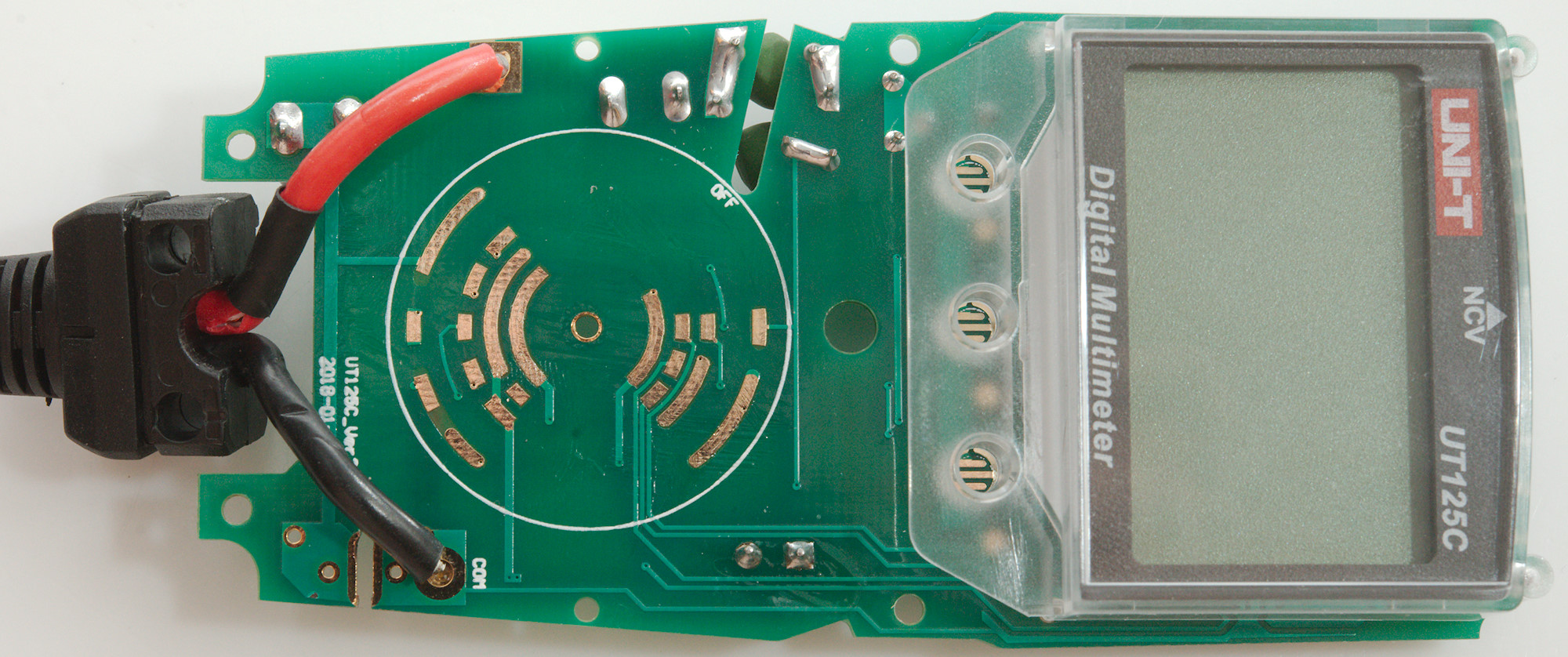
4 more screws and I could remove the circuit board, the display was another two screws.
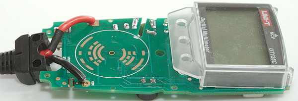
The display is not correctly mounted here, the two guiding pins must be into the holes in the circuit board.

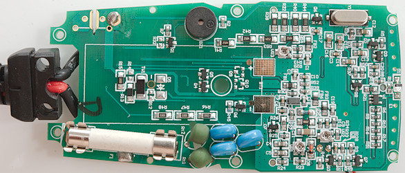
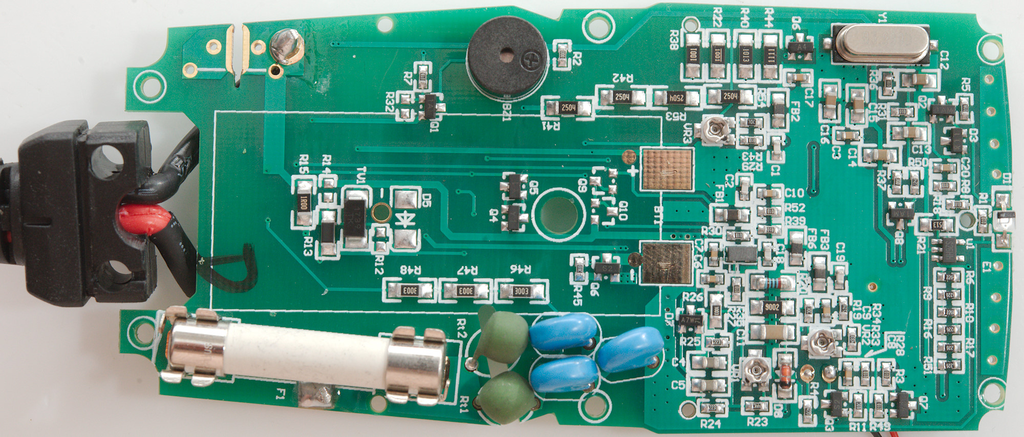
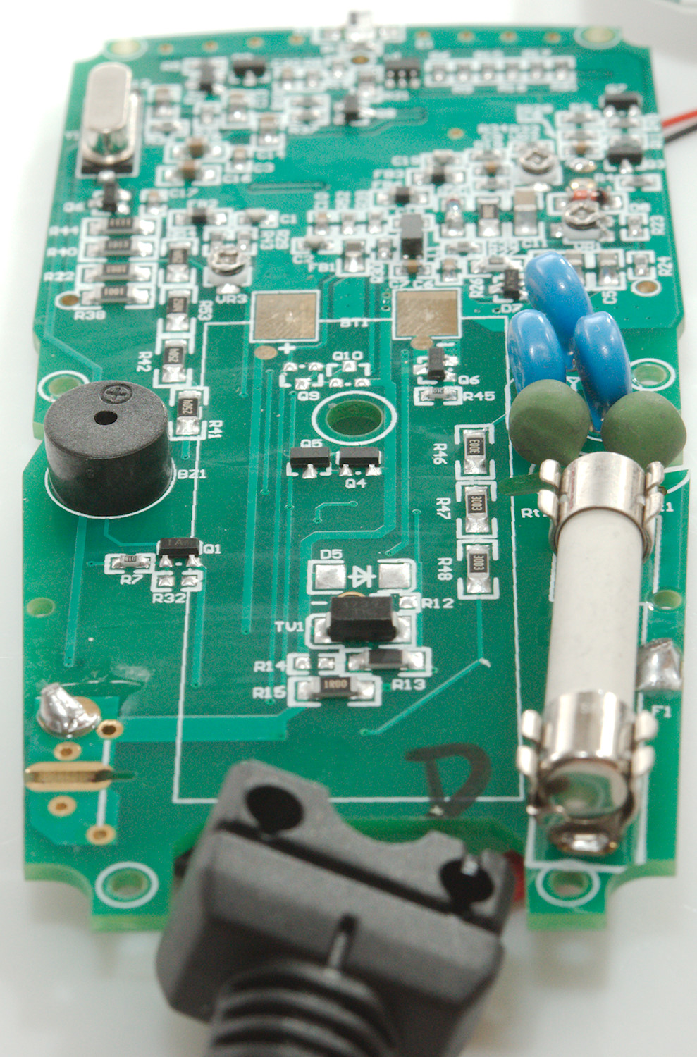
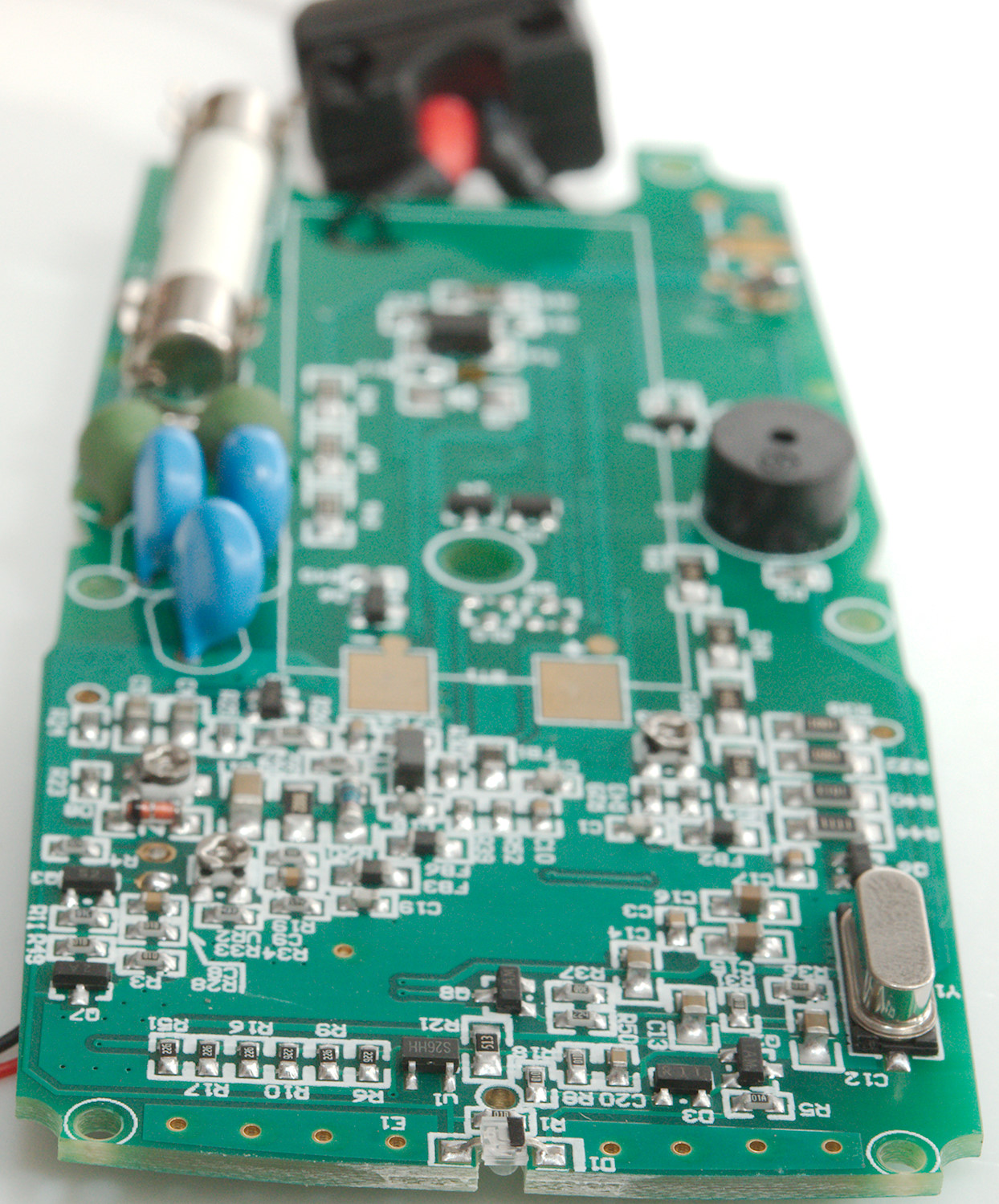
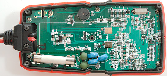
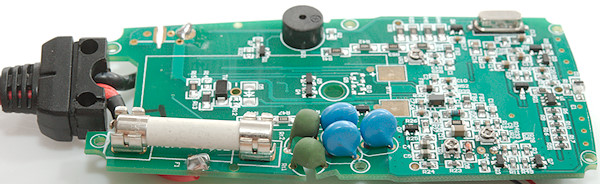
The current ranges is protected with a large fuse and a TVS diode (TV1), the mA range uses one resistor (R15: 1ohm) and the uA range two (R13 & R15: 99ohm & 1ohm).
Voltage input uses a PTC (RT2) with MOVS for over voltage protection and 4 resistors for input (R41, R42, R53, R54: 4x2.5Mohm).
Ohm uses one PTC (RT2) together with a transistor clamp (Q4 & Q5) for output protection and the other PTC (RT1) together with a 900kOhm resistor (R46, R47, R8: 3x300kOhm) for input.
The NCV antenna is at the top, it has its own chip (U1) to detect and drive the led (D1) and there is a string of resistors to control the potential (R6, R9, R10, R16, R17, R51: 6x22Mohm), this huge resistance is the reason for the high sensitivity (Shorting some of these resistors will probably make the NCV more useful).
There is 3 trimpots do adjust the meter.
One strange thing is a spark gab in the circuit board across the current shunts.

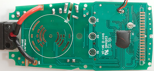
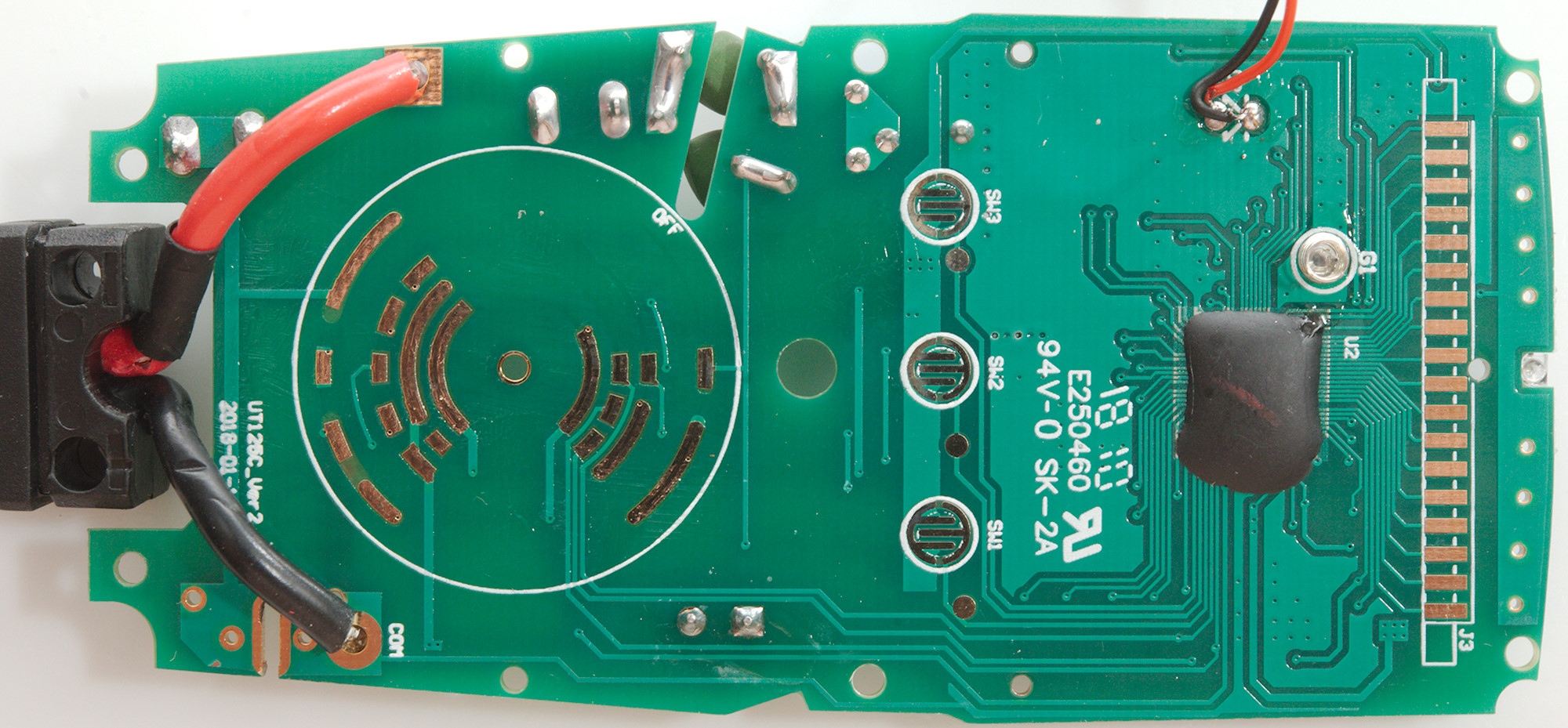
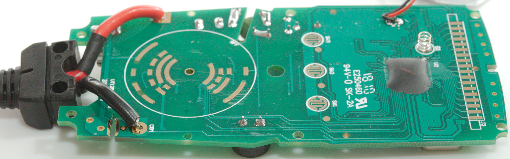
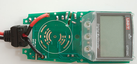
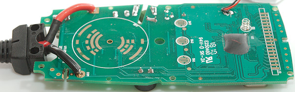
This side of the circuit board has the pads for the range switches, the buttons and the LCD, there is a spring for the foil on the back of the backlight and the multimeter chip.
The probe wires has an extra layer of isolation where the are close to the circuit board.
There is a slot below the PTC's to increase voltage handling ability.
Conclusion
This meter has a nice selection of ranges, but nothing advanced and the safety looks good.
Notes
UNI-T sell rebranded versions of their meters, i.e. you can probably get this meter with another name on it.
How do I review a DMM
More DMM reviews
Multimeter design, this explains a lot more about DMM's than my tear-downs