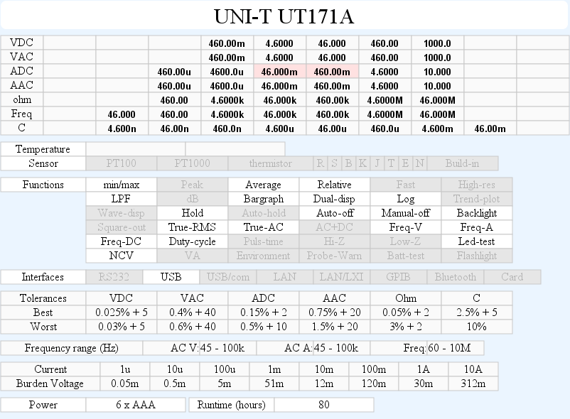
DMM UNI-T UT171A
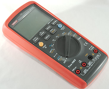
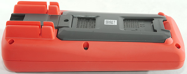
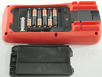
This is a industrial DMM designed with good precision and logging. It is the simplest meter in the UT171 series and uses AAA batteries, the other meters in the series has builtin LiIon batteries.
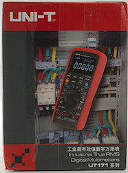
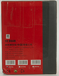
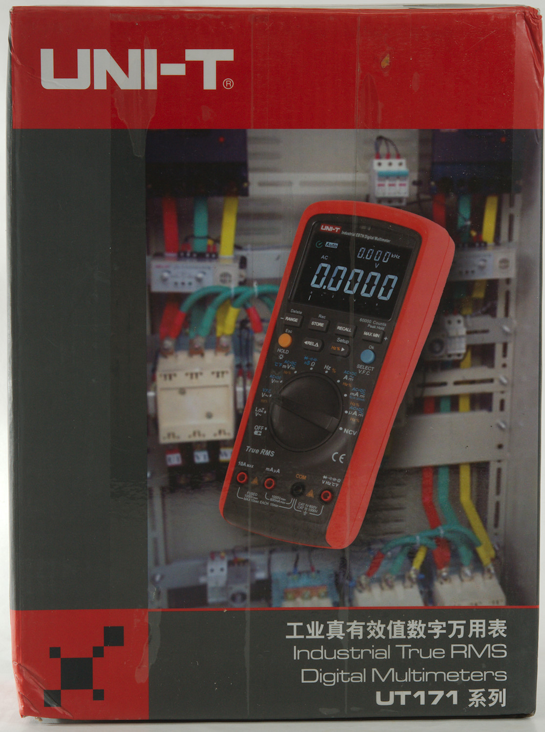
The box do not say anything about the meter and the illustration is of another model in the UT171 series.
Inside the box was only a pouch.
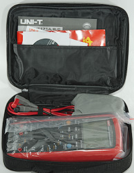
With all parts inside.
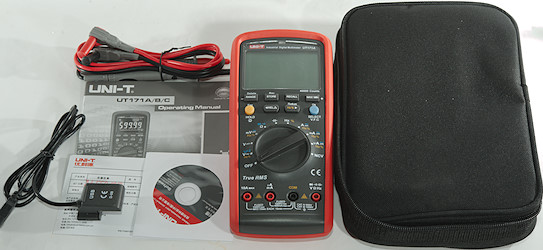
That was the meter, the probes, a CD with software and a manual (Both software and manual can be downloaded).
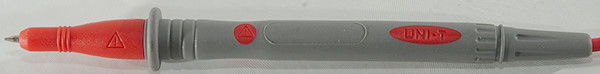
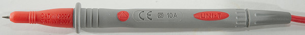
Probes are branded UNI-T and rated for 10A
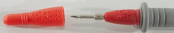
With a tip cover they are CAT IV 600V or CAT III 1000V, without CAT II 1000V (This is fairly standard for probes).
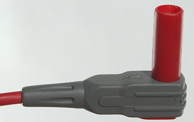
The plugs are fully shrouded, but the shroud is a bit short
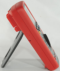
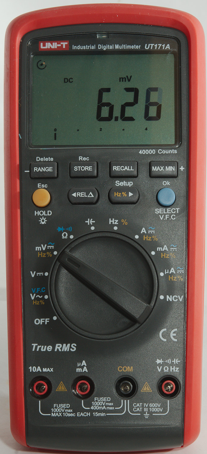
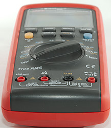
The meter is heavy enough to keep it stable while turning the range switch, this means it can easily be used with one hand, either lying flat or standing.
Display
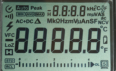
All the segments are shown during power on, not all of them are used.
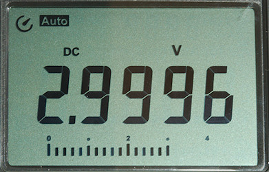
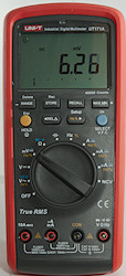
Typical display during usage, it will show the number and selected measurement
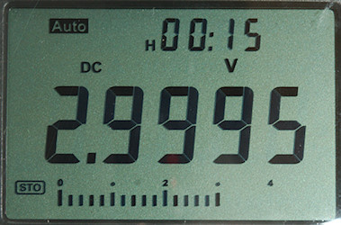
During logging the secondary display will show remaining time of logging session (May alternate with other values).
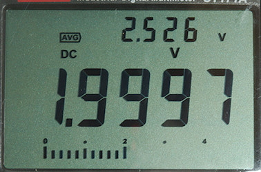
Here I have activated the max/min/avg function and the secondary display is used for these value, the main display will continue to show the input voltage.
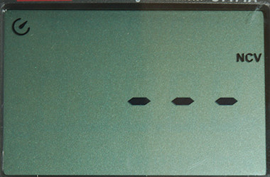
NCV display is the usual bars and a red flashing led above the display, together with the buzzer.
The secondary display is used for:
- VAC/mVAC: Frequency/duty cycle
- AAC/mAAC/uAAC: Frequency/duty cycle
- Hz: Duty cycle
- Min/max: Min/max/average
- REL: Reference value
- Range: Shortly shows selected range (4/40/400/4000 it is adjusted to the correct max value)
- Logging: Remaining time
- Recall: Record number in log.
- Store: Prompt text
- Setup: Parameter value, main display is prompt text.
Functions
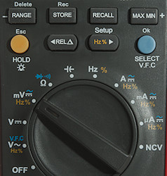
Buttons:
- Range: Select manual range and change range, hold down to reactivate automatic ranging (I did not find any usage for Delete).
- Store: Store a single value in the log, hold down to start recording (Meter will prompt for record interval and record time).
- Recall: Press to recall last value from the log, use arrow keys to move around, end with Esc.
- Max Min: Start max/min/average function, press to select readout in secondary display, main display will show actual value.
- Hold/Esc (Yellow): Will freeze the display reading, until pressed again, hold down to activate backlight. When in configuration it is a escape button.
- Rel: Shows values relative to current value, will also select manual range (Reference value is show in secondary display). Press again to disable.
- Hz % Setup: Select frequency/duty cycle in AC voltage and current modes, hold down to enter configuration.
- Ok Select VFC: Select AC in mV and current modes, hold down to activate LPF in VAC mode.
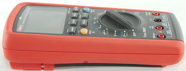
Rotary switch:
- Off: Meter is turned off
- VAC/VFC: AC voltage, hold blue button down to activate LPF (Low pass filter)
- DCV: DC voltage
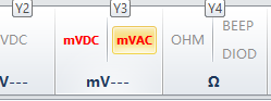
- mV: AC or DC milli volt
 : Ohm, continuity and diode.
 : Capacitance.
- Hz: Logical frequency input.
- A: Ampere DC or AC
- mA: Milli ampere DC or AC
- uA: Micro ampere DC or AC
- NCV: Non contact voltage, this is not very sensitive.
Input
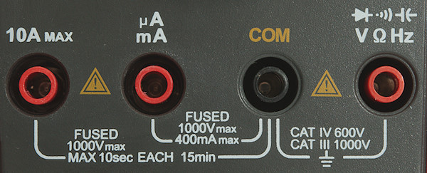
- 10ADC: 10A DC current input.
- uAmA: Micro and milliampere input.
- COM: The common terminal for all ranges.
- xxx: All other ranges.
Measurements
- Volt and frequency
- 1V AC readings is 5% down at 130kHz, rms will not work at that frequency
- 7V AC readings in VFC is 5% down at 430Hz, rms will not work at that frequency
- Frequency input do not require a zero crossing, it has a capacitor at the input.
- At 0.1Vrms frequency input range is from 2Hz to 1MHz
- At 1Vrms frequency input range is from 2Hz to 20MHz
- At 3Vrms frequency input range is from 2Hz to 47MHz
- Duty cycle works from 30% to 80% at 100kHz with 4Vpp, precision is within 6.0.
- Duty cycle works from 20% to 91% at 10kHz with 2Vpp, precision is within 1.0.
- Max/min needs about 280ms to capture a voltage, autorange is disabled when using this function.
- Input impedance is 10-11Mohm on DC, AC has a capacitor in input.
- mV AC/DC is 10Mohm below 2V where it drops to a few kOhm (Manual specify high impedance, but that is not correct).
- Maximum voltage not specified.
- Current
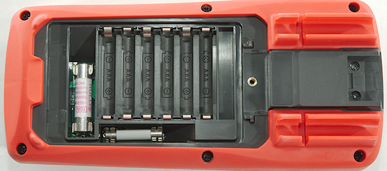
- 10A range is fused with a 10A/1000V 10x38mm fuse
- mAuA range is fused with a 0.8A/1000V 6x32mm fuse
- Display will show "Lead" when leads are in the wrong terminal and the buzzer will sound if a current terminal is used when not expected.
- Ohm, continuity, diode and capacitance
- Ohm needs about 0.8s to measure 100ohm
- Ohm voltage is 1.0V open and 0.65mA shorted.
- Continuity is quick (About 80ms).
- Continuity beeps when resistance is below 15ohm.
- Continuity is 2.1V open and 0.65mA shorted
- Diode range uses 3.1V, max. display is 3.000V at 0.06mA, max. current is 1.0mA shorted
- 10uF takes about 1.6 second to measure.
- 11000uF takes about 8 seconds to measure.
- Overload protection is not specified.
- Miscellaneous
- Current consumption of meter is 12mA (16mA with backlight at 50%).
- Meter turns off at 6.8V, battery symbol show at 7.3V.
- Readings will be correct until meter turn off.
- Backlight is fairly stable until meter turns off
- Viewing angle is good
- The meter can log 1000 values, there is no concept of files, all values are saved in on long list.
- Display updates around 5 times/sec
- Bargraph updates faster than numbers.
- Configuration: Auto power off, Auto backlight off, Erase log, Brightness, USB, Buzzer
- Backlight can be configured in 5 to 30 seconds auto turnoff or never.
- Power can be configured in 5 to 30 minutes auto turnoff or never.
- Standard probes cannot be fully seated in the meter, but they do connect.
- The meter usual shows the correct value at first update.
- Weight is 515g without accessories, but with battery.
- Size is 206 x 95 x 53mm
- Probes
- Probe resistance 30mOhm for one.
- Probe wire are 88cm long.
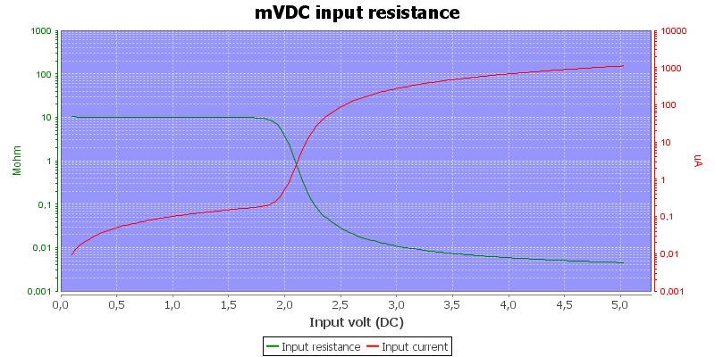
mVDC is high impedance up to about 2V.
The 40mA DCA range is 0.35% wrong, this is outside specified tolerance.
The 400mA DCA range is 0.39% wrong, this is outside specified tolerance.
Software on PC
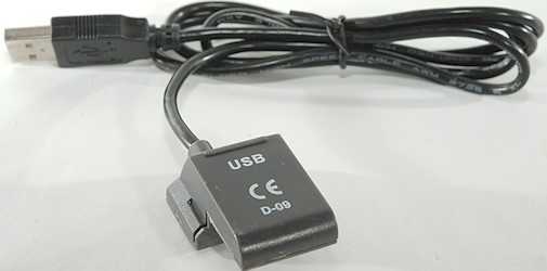
The software and usb cable for a computer connection is supplied. The software is on a mini CD (Can also be downloaded), it contains the software and a very basic manual for the software. The adapter is a HID device.
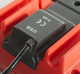
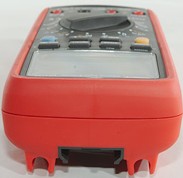
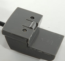
The adapter is slided in at the top of the meter. Remember to enable usb in configuration each time the meter is turned on and you want to use usb.
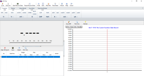
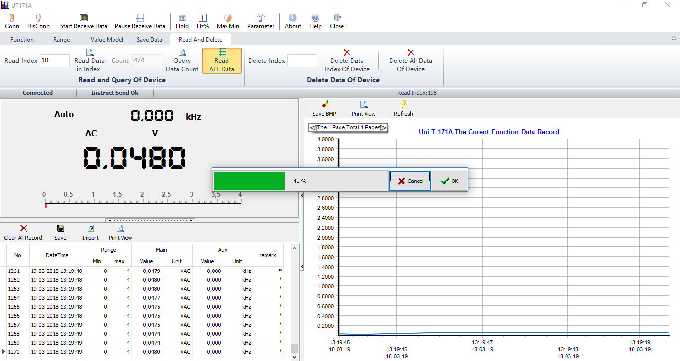
When starting the software looks this way on a Windows 10 computer. The software can basically remote control anything on the meter, except the range switch (Rel works differently: the reference value must be entered).
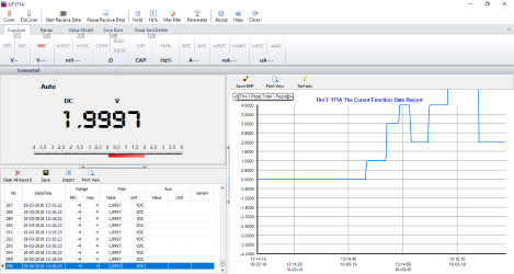
Connected to the meter and receiving data.
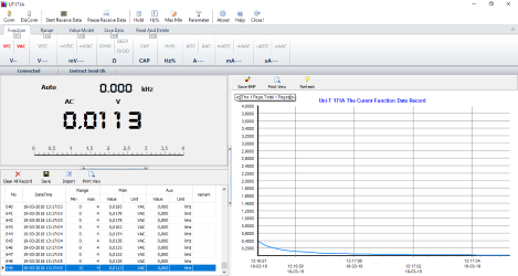
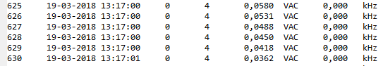
In AC ranges the frequency is shown together with the main value in the readout and in the table.
The select button is controlled from this area.
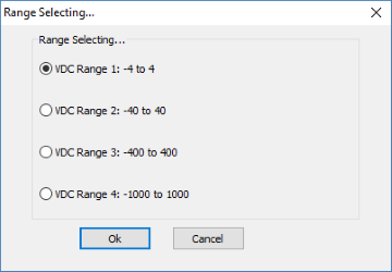
Using manual range select allows directly selecting the desired range.
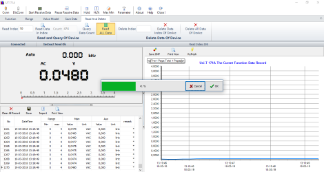
Downloading data from the meter is not very well designed, readings are fetched one at a time, this means the software can only download a few readings each second, i.e. it takes a long time downloading data.
Data will just be added to the current measurement set of data with the current time as timestamp.
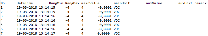
The software saves in a tab file format.
On lines where the secondary display showed a value this will be included in the line. There is no identification about what the second value is, except unit, this is problematic with min/max/avg/rel.
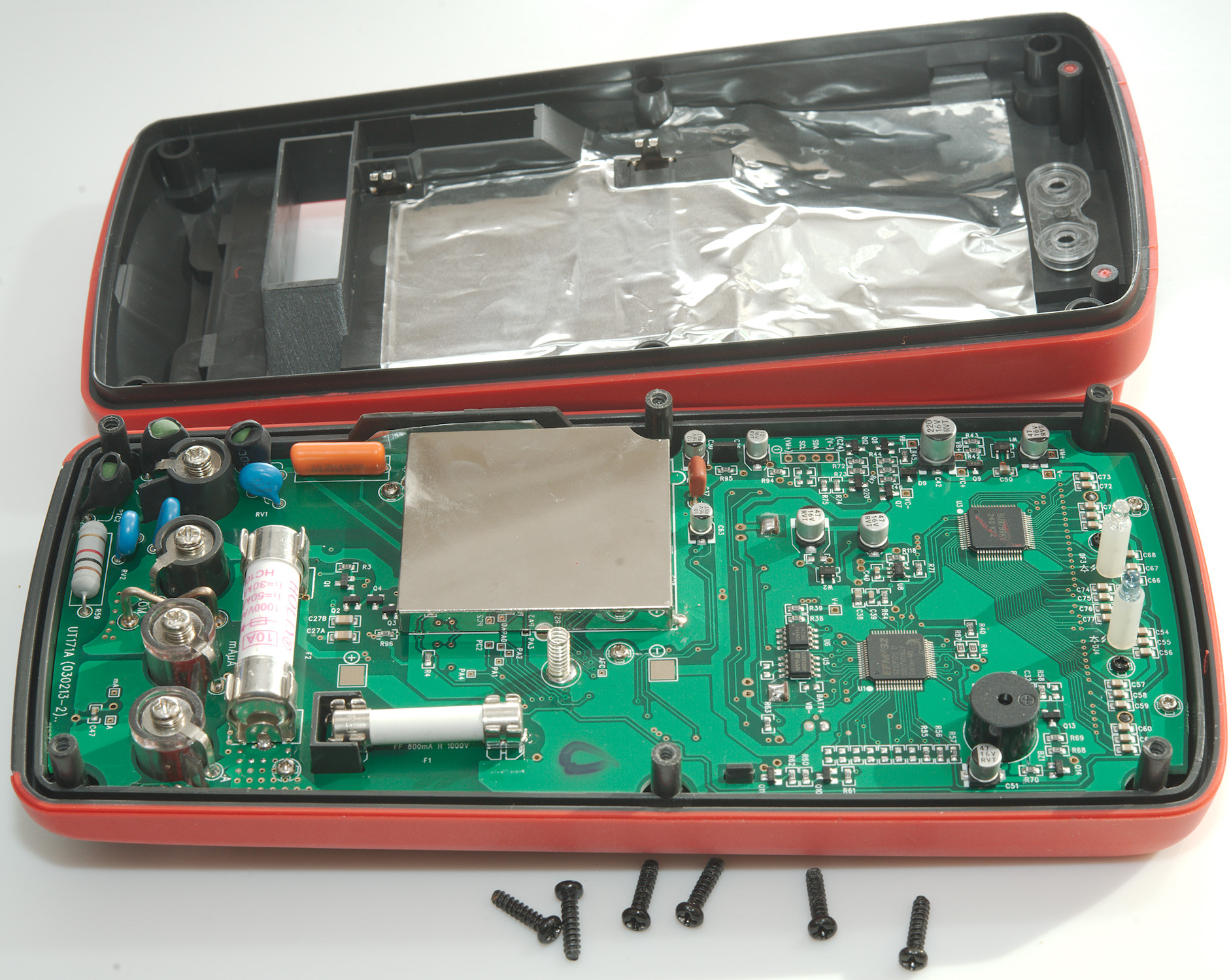
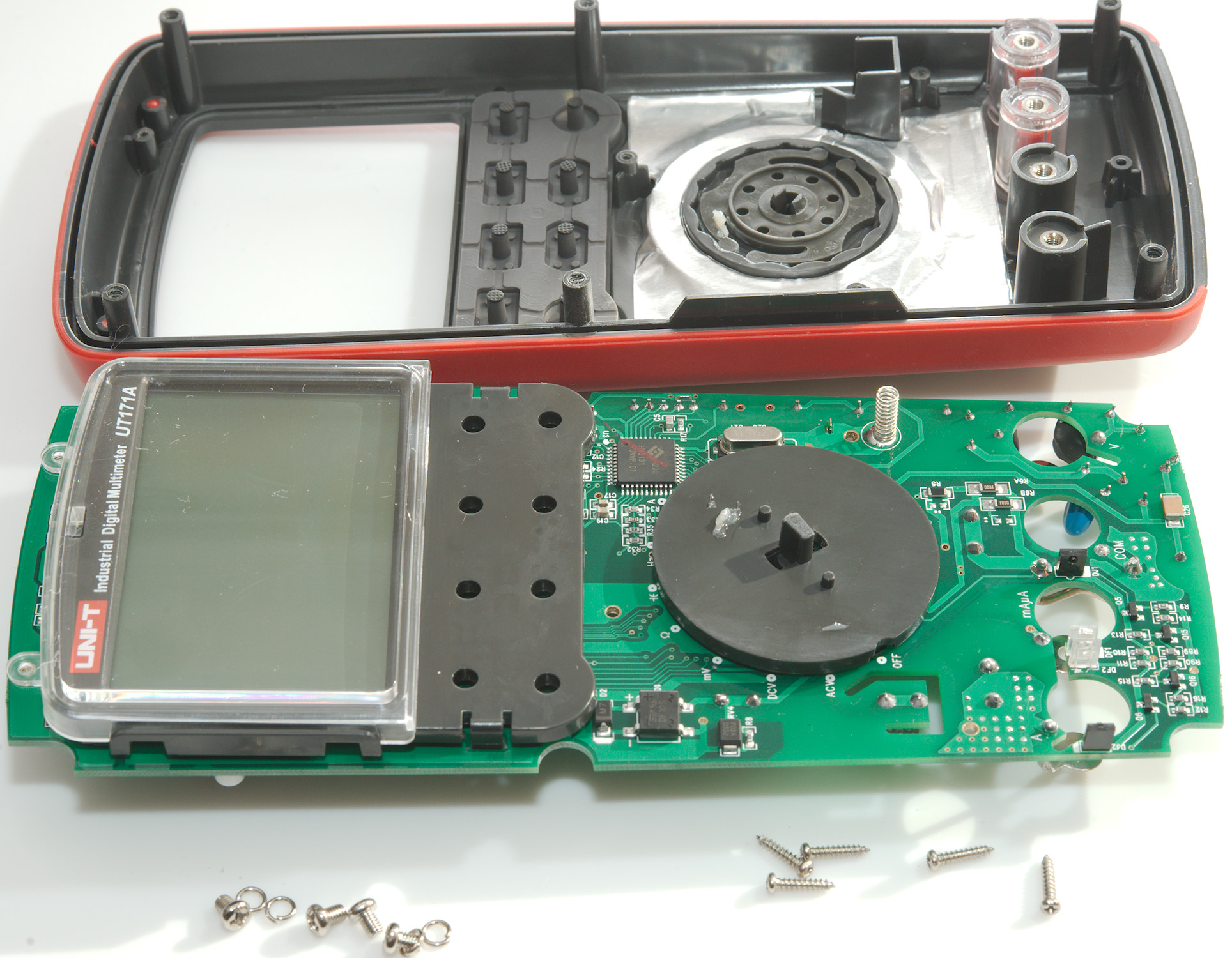
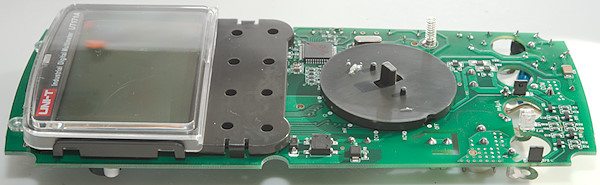
Tear down
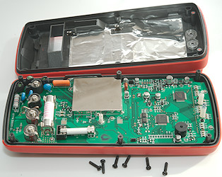
I had to remove 6 screws to open the meter.
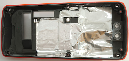
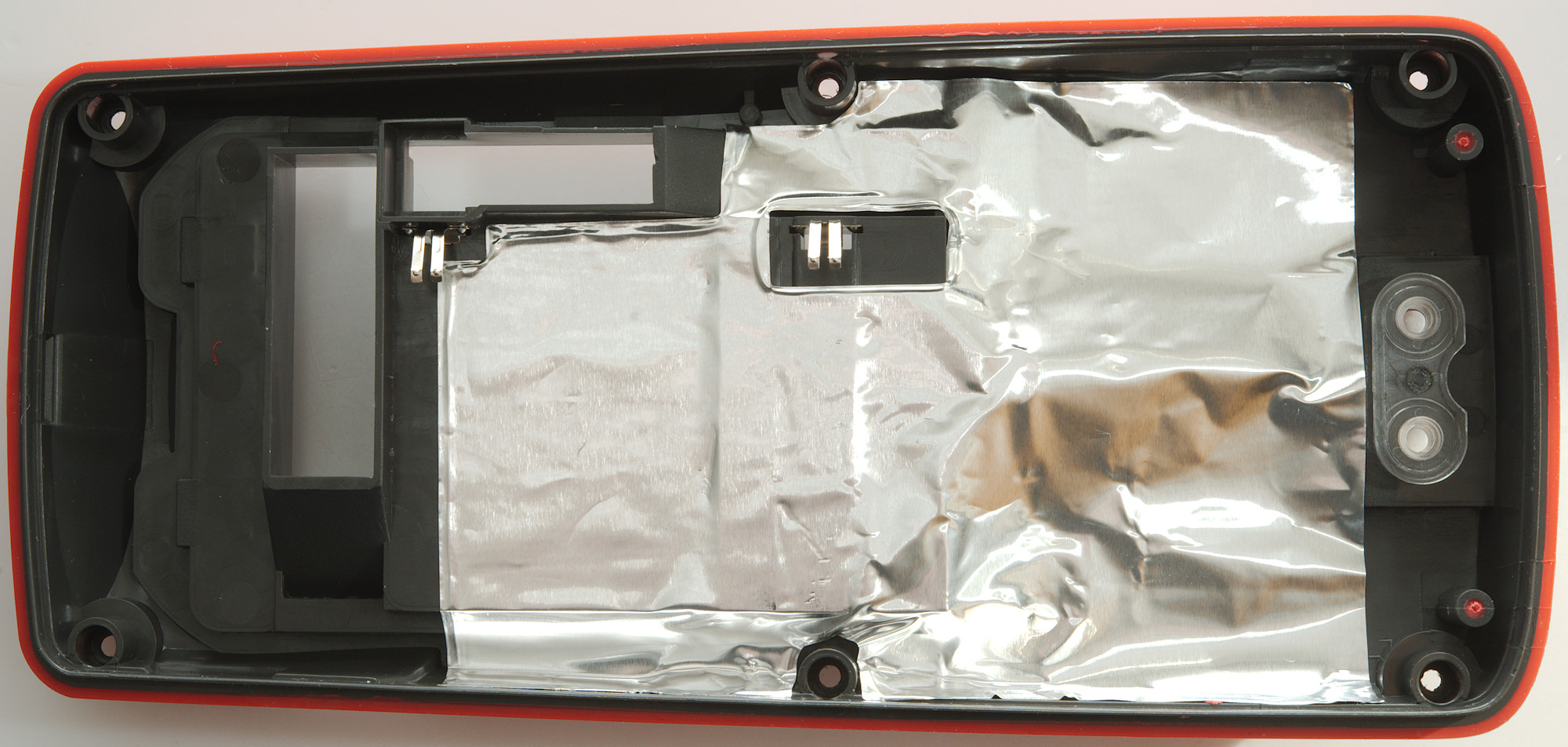
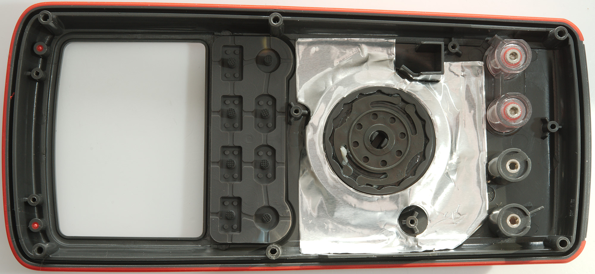
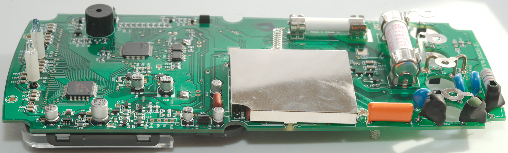
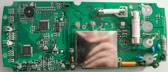
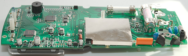
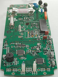
There is a lot of shielding in the meter, both metal foil in the back and a metal can on the circuit board.

Four screws for the input terminals and 5 more screws was holding the circuit board.
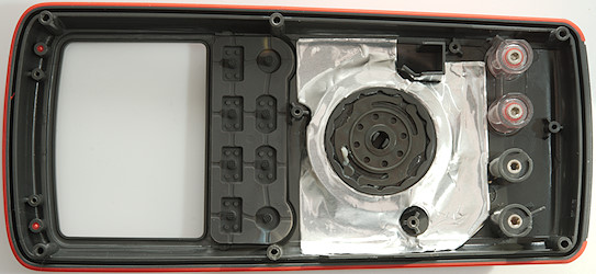
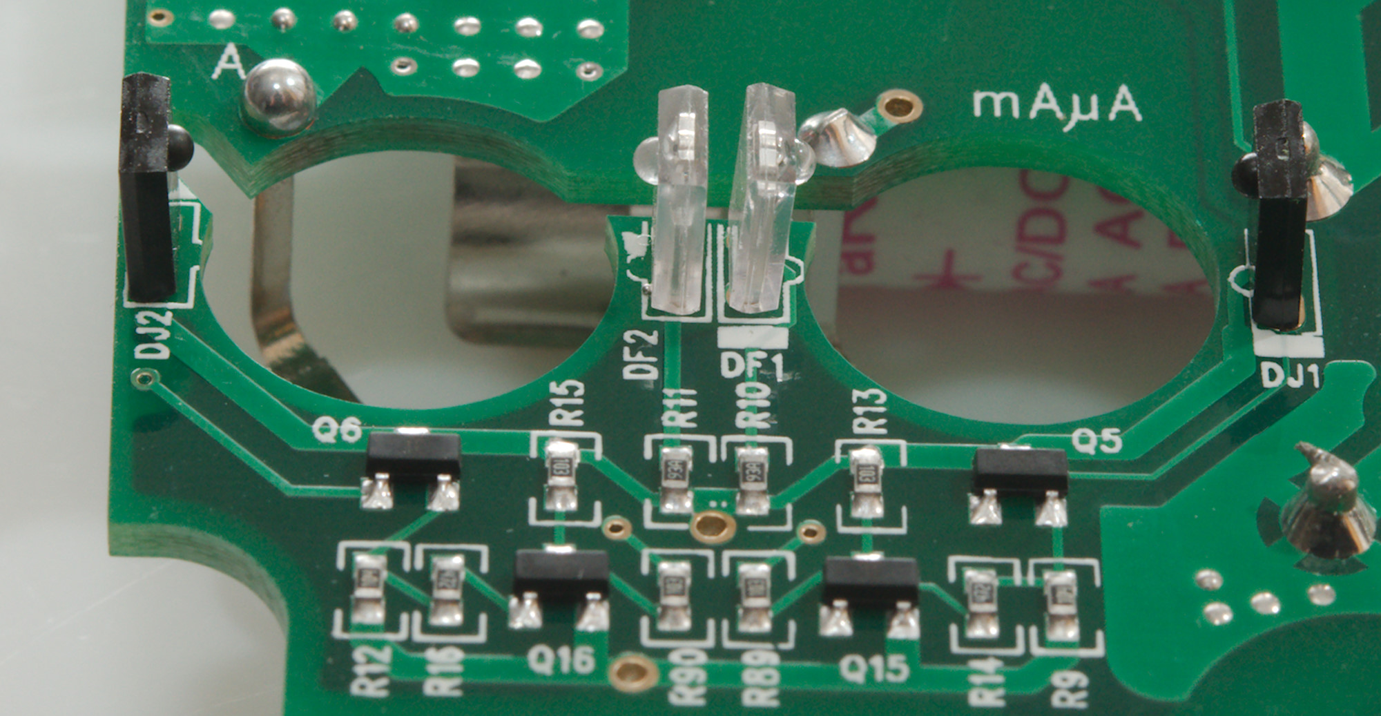
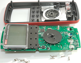
There is also some shielding on the front. The current input terminals are in clear plastic.
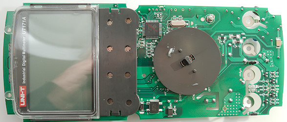
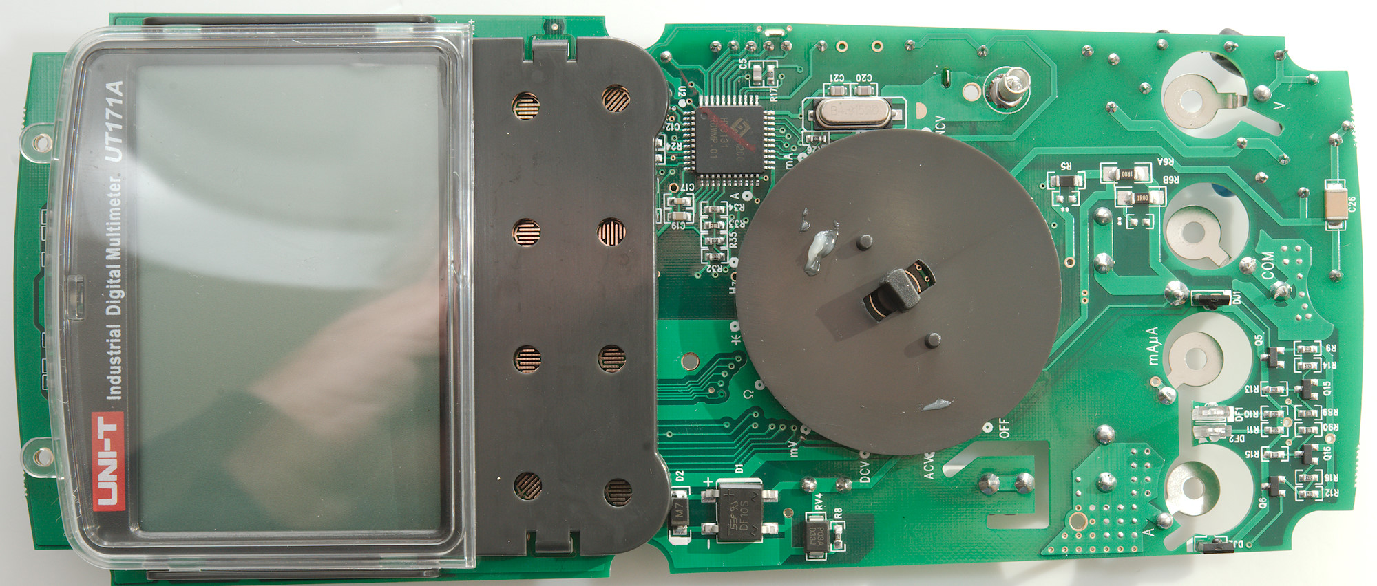
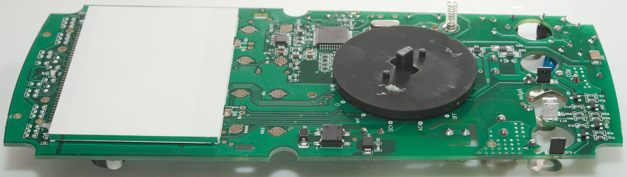
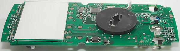
Display is mounted on the circuit board and the range switch also sticks to the circuit board.
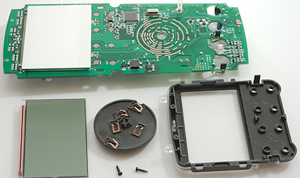
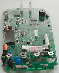
Two more screws and the display could be removed, the range switch could just be pulled off.
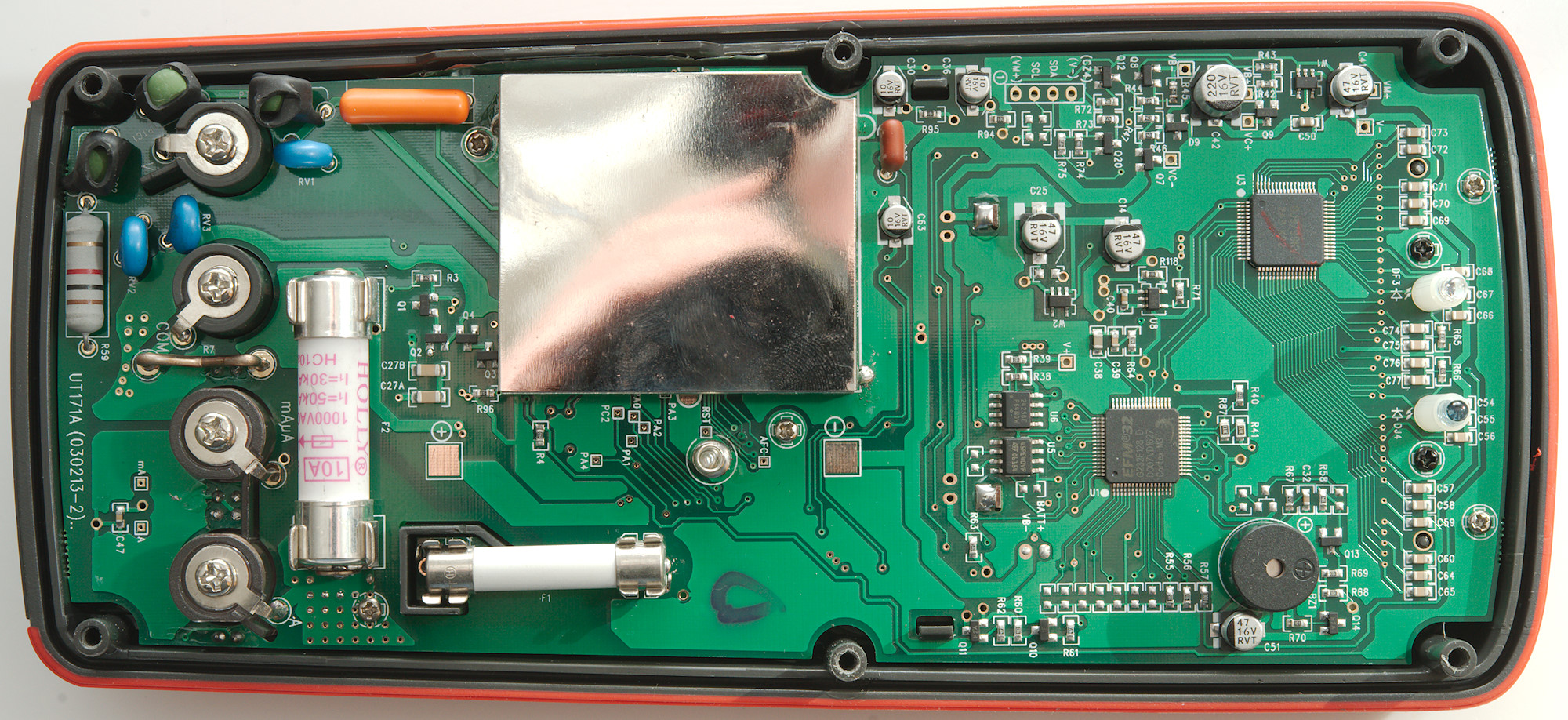
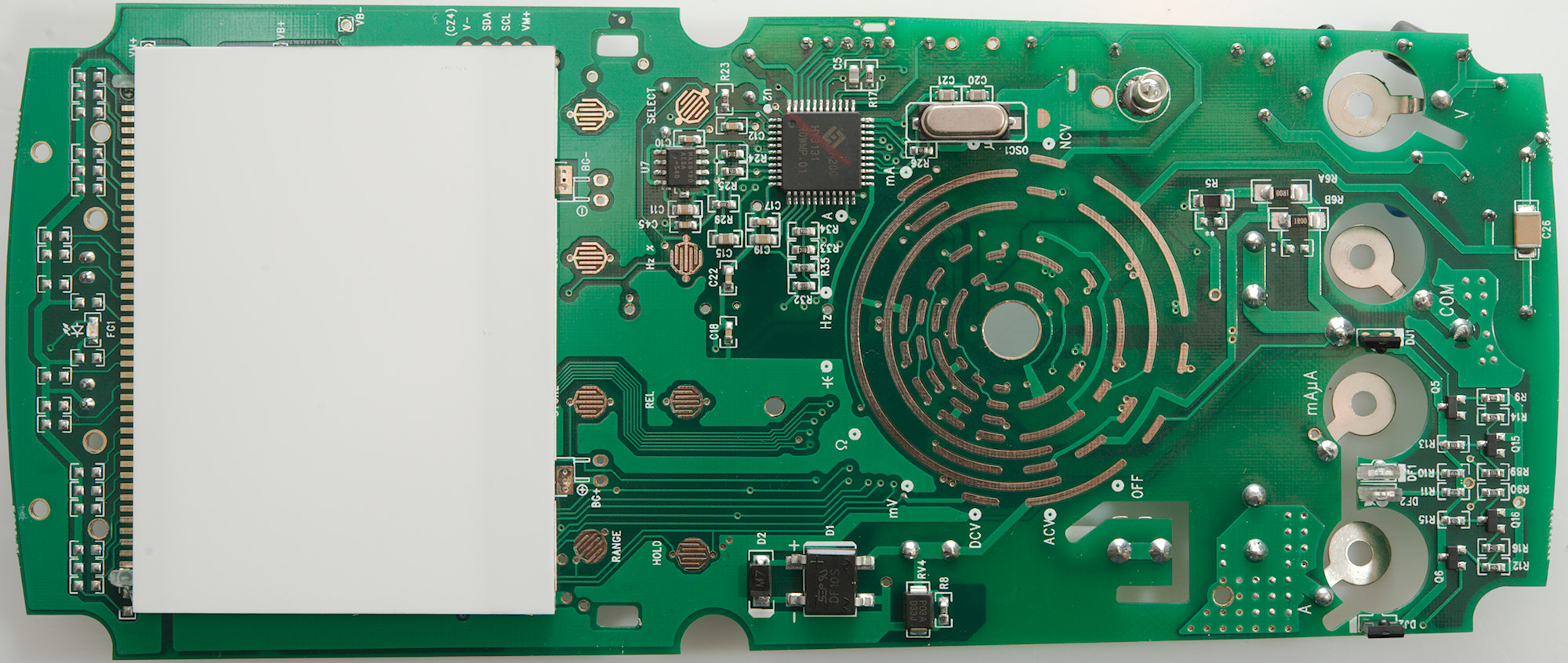
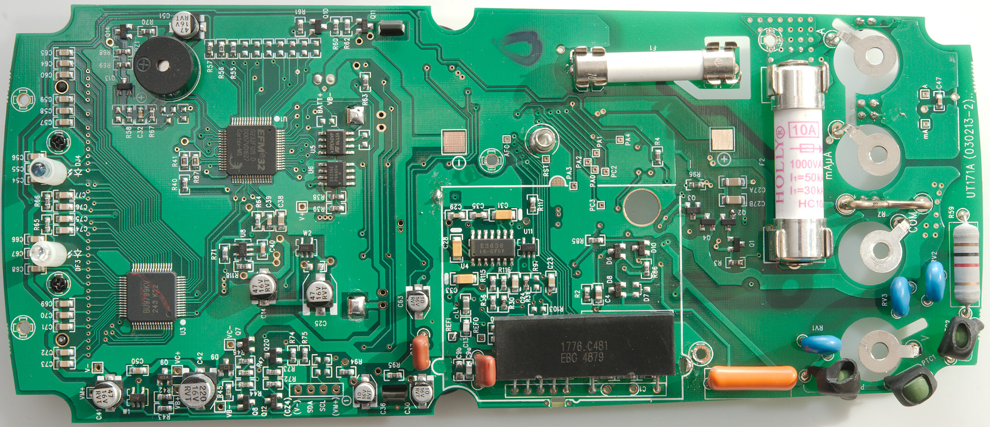
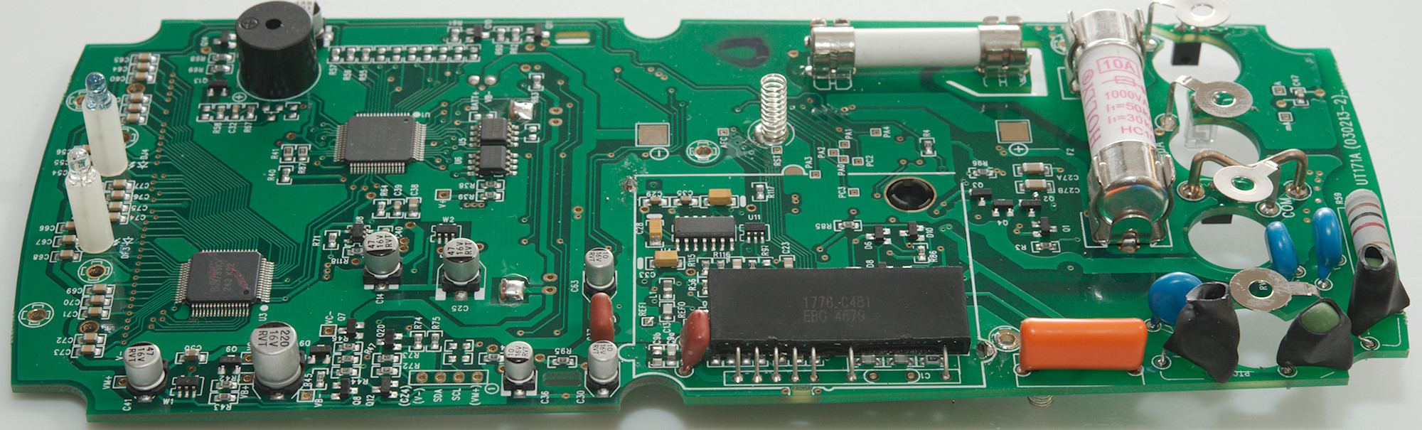
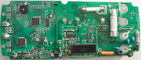
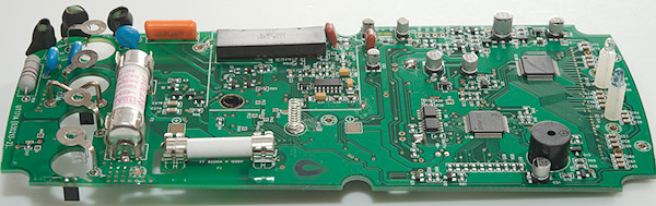
It looks like we have the current shunts on this side, both for mA (R6A & R6B: 2x1ohm) and uA (R5: 50ohm). The protection for these shunts are some diodes (D1, D2, RV4) and the 0.8A fuse on the other side.
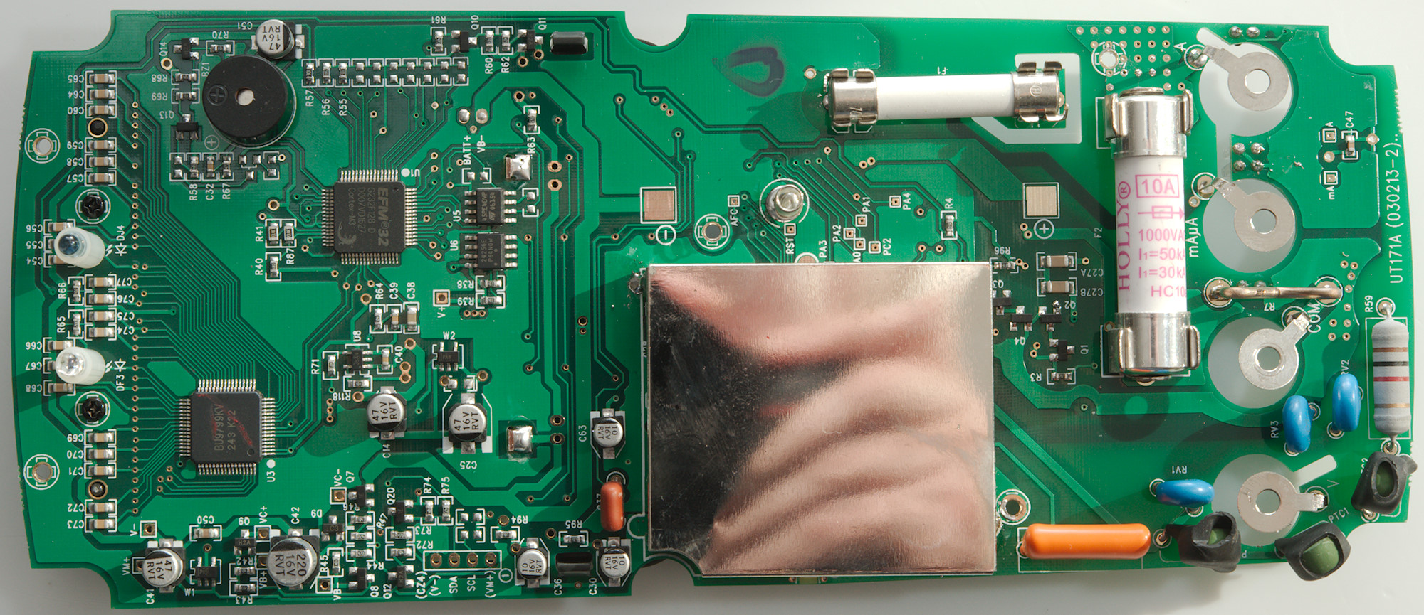
The analog frontend is also here (U2: HY3131 50000 count) and a reference (U7: MAX6190).
It looks like the top of the circuit board is antenna for the NCV input. The NCV led is also in that area (FG1). The backlight panel is soldered to the circuit board where it is marked BG+ and BG-.
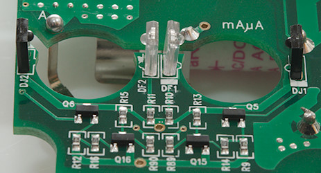
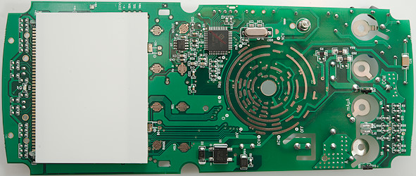
A closer look at the area around the A and mAuA input terminals. There is two leds (DF1, DF2) and two receivers (DJ1, DJ2) and then some circuit to amplify the signal. This is the probe detection for the terminals and the reason they are of clear plastic.
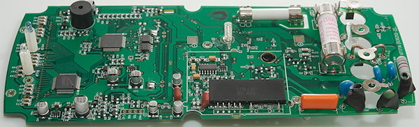
The can is blocking for some parts, what can that be?
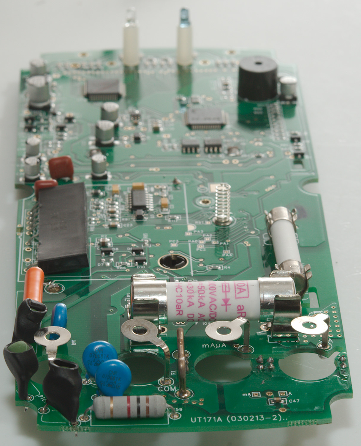
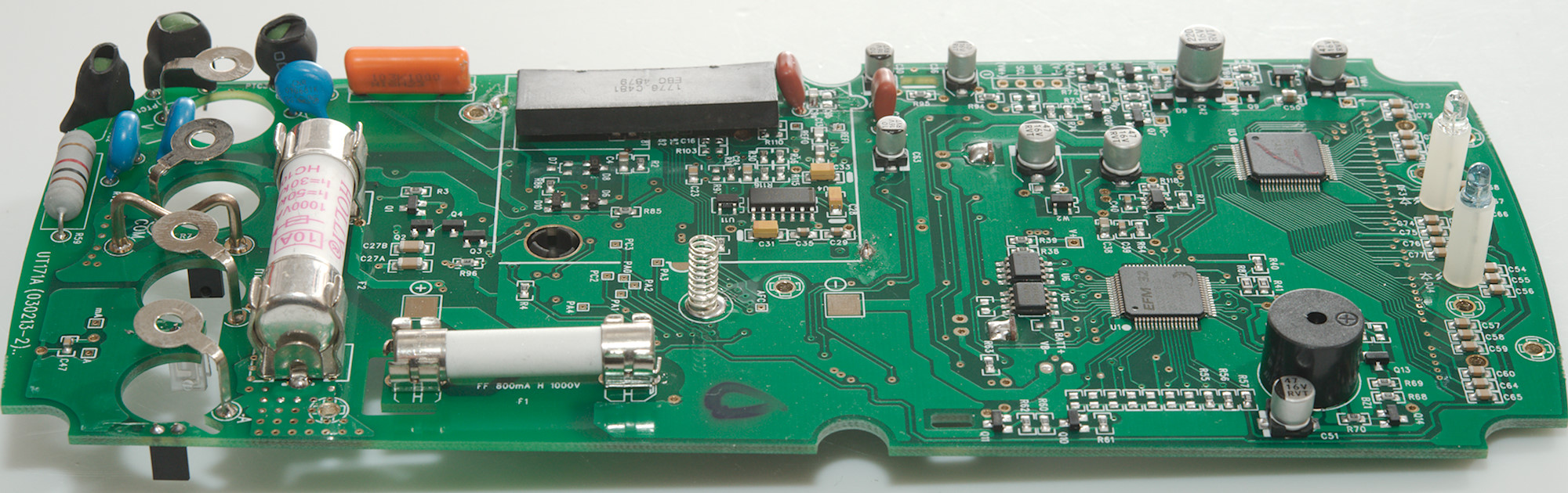
At the V input there are two paths with PTC's: First one uses two PTC's (PTC1 & PTC3), the other path is a PTC (PTC2) and a resistor (R59: 1kOhm). Both path has a two MOV's to COM input, one of them shared (RV3). The big orange part is a capacitor (10nF 1000V) used for AC ranges. There is also some transistor pairs for protection: mV, ohm, capacitance (Q1 & Q2), ohm & capacitance (Q3, Q4).
The can contains a large precision resistor and the true rms converter (U4: ES636).
Next up is two memory chips a EEPROM (U6: 24256E 32Kx8) and a flash (U5: M45PE40VP 512k*8), next to the microprocessor (U1: EFM32G232F128 ARM). This processor cannot directly drive a large LCD and need some help (U3: BU9799KV 50x4 LCD driver).
The two leds for the computer interface (DF3 & DJ4) is raised well above the circuit board.
Conclusion
This meter looks well protected and may live up to its CAT rating.
It has good precision with all the common ranges, the computer connection works fine for logging, but off-line logging is not very useful. The high AC bandwidth and average function are nice details, but duty cycle do not handle high frequencies very well.
The mA and uA current ranges has lower burden voltage due to the lower shunt values, this is most obvious in the high uA range, but also helps slightly in the high mA range.
Generally a very nice and fast meter, but I am missing temperature measurement.
Notes
UNI-T do often make rebranded meters, i.e. it may exist with other names on it.
How do I review a DMM
More DMM reviews