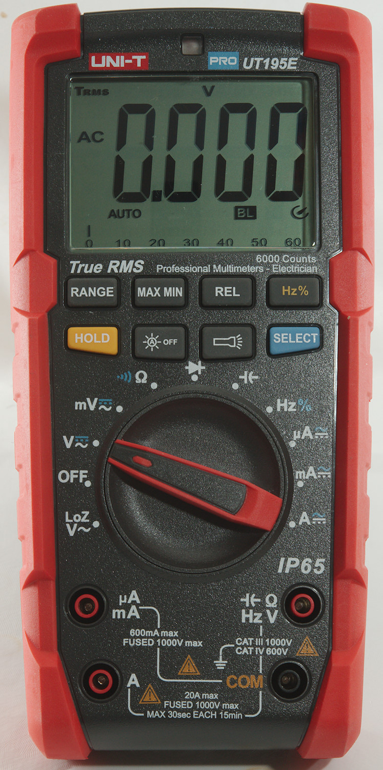
DMM UNI-T UT195E
This is a industrial grade DMM designed for electricians. This is the simplest of the meters in the 195 series.

I got it without the box, but in the pouch.
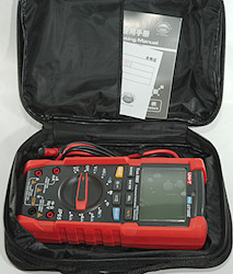
With all parts inside.
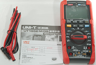
That was the meter, the probes and a Chinese manual (I could download an English version).

Probes are branded UNI-T and rated for 20A, they have very low resistance and the 20A rating looks good enough.

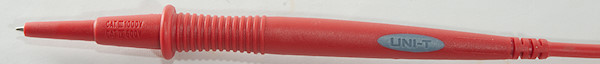
With a tip cover they are CAT IV 600V or CAT III 1000V, without CAT II 1000V (This is fairly standard for probes).
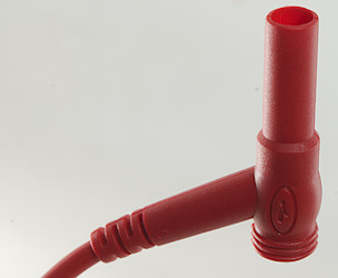
The plugs are fully shrouded, but the shroud is a bit short
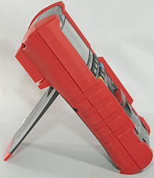

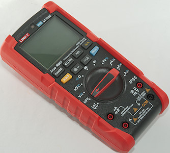
The meter is fairly heavy and the range switch easy to turn, this means it can easily be used with one hand, either lying flat or standing.
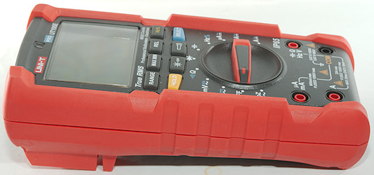
All the red plastic is slightly rubberized in feel including the range switch.
The red plastic works as bumbers from any direction.
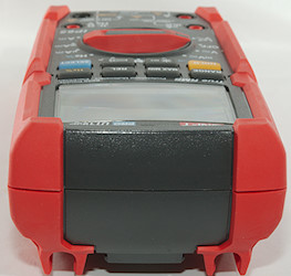
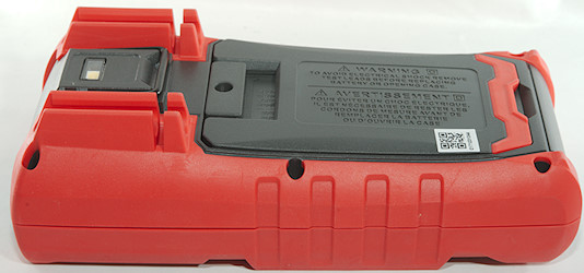

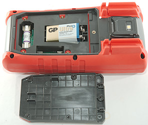
The battery/fuse compartment is sealed and due to that the lid uses 5 screws, that usual stays in the lid (i.e. no lost screws).
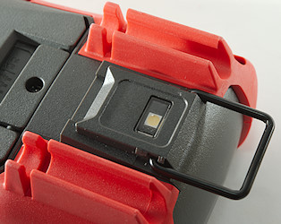
The flashlight led and a hanger.
Display
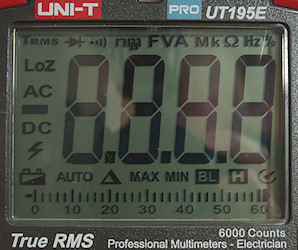
All the segments are shown during power on.
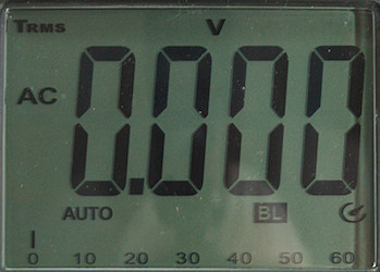
Typical display during usage, it will show the number and selected measurement
Functions
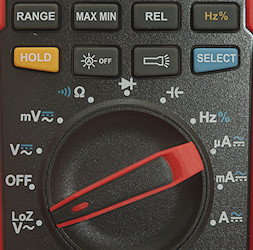
Buttons:
- Range: Select manual range and change range, hold down to reactivate automatic ranging (Hz and C is always auto).
- Max/min: Capture maximum and minimum values, it will change between max/min, bargraph will show actual value. Hold down to disable.
- Rel: Shows values relative to current value, will also select manual range. Press again to disable.
- Hz %: Show frequency and duty cycle in AC voltage and current ranges, in Hz mode it will select duty cycle.
- Hold (Yellow): Will freeze the display reading, until pressed again.
 : Turn automatic backlight off until next power cycle.
 : Turn flashlight on or off.
- Select (Blue): Select DC/AC in voltage and current modes, continuity in ohm mode and can also be used to show duty cycle in Hz mode.
Rotary switch:
- LoZ: Low input impedance (300kOhm), range is always 600VAC.
- Off: Meter is turned off
- V: AC or DC voltage
- mV: AC or DC milli volt
 : Ohm and continuity.
 : Diode.
 : Capacitanse.
- Hz: Logical frequency input.
- uA: Micro ampere DC or AC
- mA: Milli ampere DC or AC
- A: Ampere DC or AC
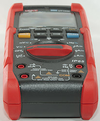
Input
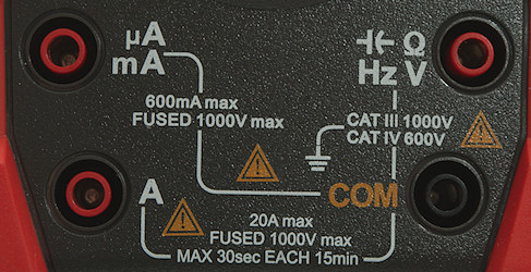
- uAmA: Micro and milli ampere input.
- 20ADC: 20A DC current input.
- COM: The common terminal for all ranges.
- xxx: All other ranges.
Measurements
- Volt and frequency
- Volt ranges starts in AC
- 1V AC readings is 5% down at 2kHz, rms will not work at that frequency
- Frequency input do not require a zero crossing.
- At 0.1Vrms frequency input range is from 1Hz to 4MHz
- At 1Vrms frequency input range is from 1Hz to 24MHz
- Duty cycle works from 7% to 97% at 100kHz with 4Vpp, precision is within 0.4.
- Max/min needs about 390ms to capture a voltage, autorange is disabled when using this function.
- Input impedance is 10-11Mohm on DC and AC
- mVDC is high impedance up to about 2V where it drops to about 20kOhm, above 14V it will drop to 3kOhm
- mVAC is the same, but capped by a 10MOhm resistor.
- LowZ is constant 300kOhm input impedance and is locked in 600VAC range.
- Input protection is 1000VDC/750VAC
- Current
- 20A range has audible alarm above 20A
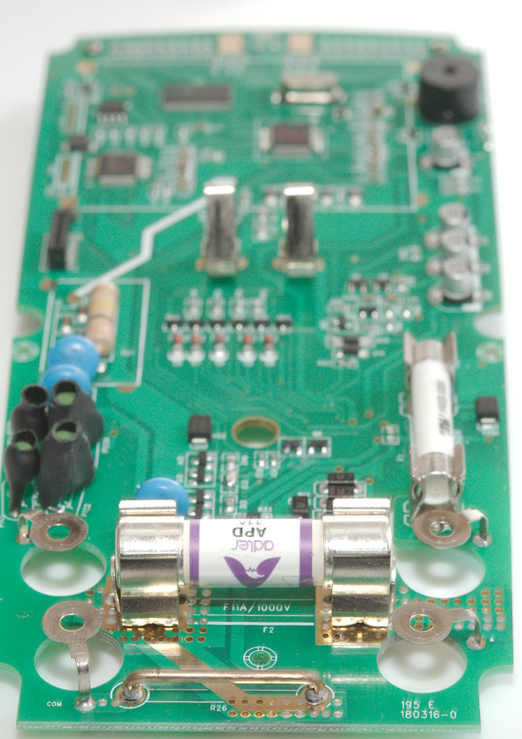
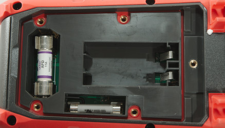
- 20A range is fused with a 11A/1000V 10x38mm fuse
- mAuA range is fused with a 0.6A/1000V 6x32mm fuse
- Current ranges starts in DC
- Peak can be selected in AAC.
- Ohm, continuity, diode and capacitance
- Ohm needs about 2.6s to measure 100ohm
- Ohm voltage is 1.0V open and 0.26mA shorted.
- Continuity is very fast (About 10ms).
- Continuity beeps when resistance is below 50ohm.
- Continuity is 1.0V open and 0.26mA shorted
- Diode range uses 3.8V, max. display is 3.000V at 0.33mA, max. current is 1.5mA shorted
- 10uF takes about 1 seconds to measure.
- 11000uF takes about 7 seconds to measure.
- Overload protection is 1000V
- Miscellaneous
- Current consumption of meter is 2.4 to 3mA (16mA with flashlight, 8mA with background light, max. 21mA).
- Display starts fading around 3.2V and is gone at 2.2V, battery symbol show at 7.3V.
- Readings will be correct until the display is faded.
- Backlight fades with dropping voltage and is mostly gone at 5.5V
- Flashlight fades with dropping voltage and is mostly gone at 3V
- Viewing angle is good
- Display updates around 3 times/sec
- Bargraph updates around 10 times/sec
- Backlight will automatic turn on when in dark surroundings
- Flashlight will not turn off automatic, but turns off with the auto power off.
- Will automatic turn power off in about 15 minutes.
- Standard probes cannot be fully seated in the meter, but they do connect.
- The meter usual need a few display update to before it display the value.
- Weight is 490g without accessories, but with battery.
- Size is 195 x 96 x 61mm
- Probes
- Probe resistance 17mOhm for one, that is very low.
- Probe wire are 88cm long and feels a bit stiff, probably due to the thickness.
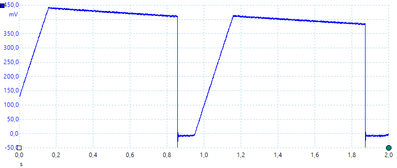
A look at the capacitance measuring waveform with a 1uF capacitor.
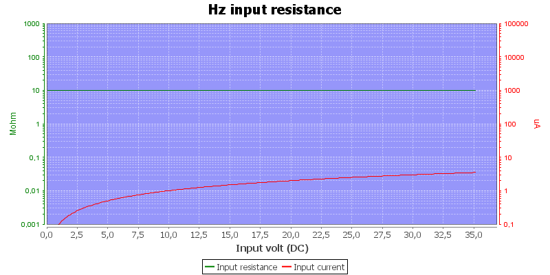
Frequency input is constant 10Mohm resistance.
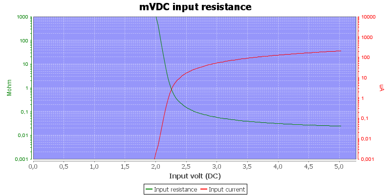
mVDC is high impedance up to about 2V.
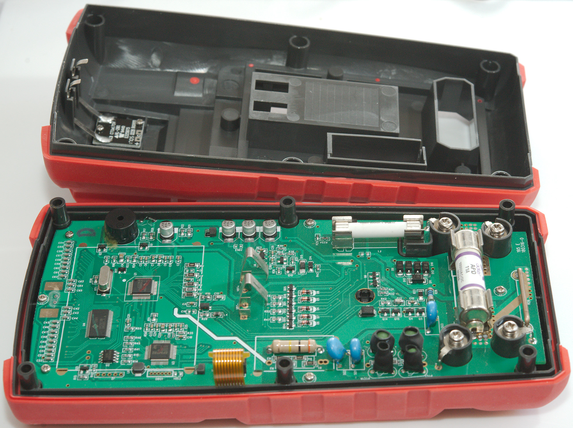
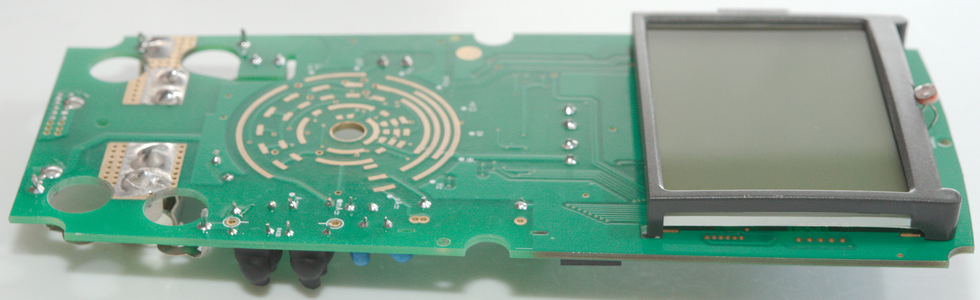
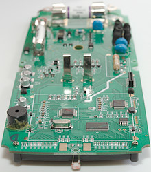
Tear down
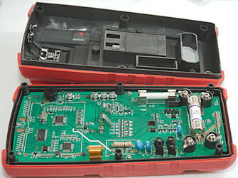
I had to remove 6 screws to open the meter. This meter uses metal inserts for the screws and they stay in the bottom (very nice).
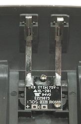
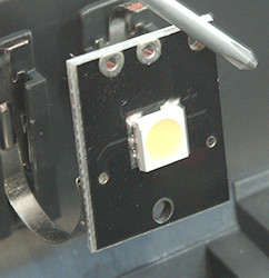
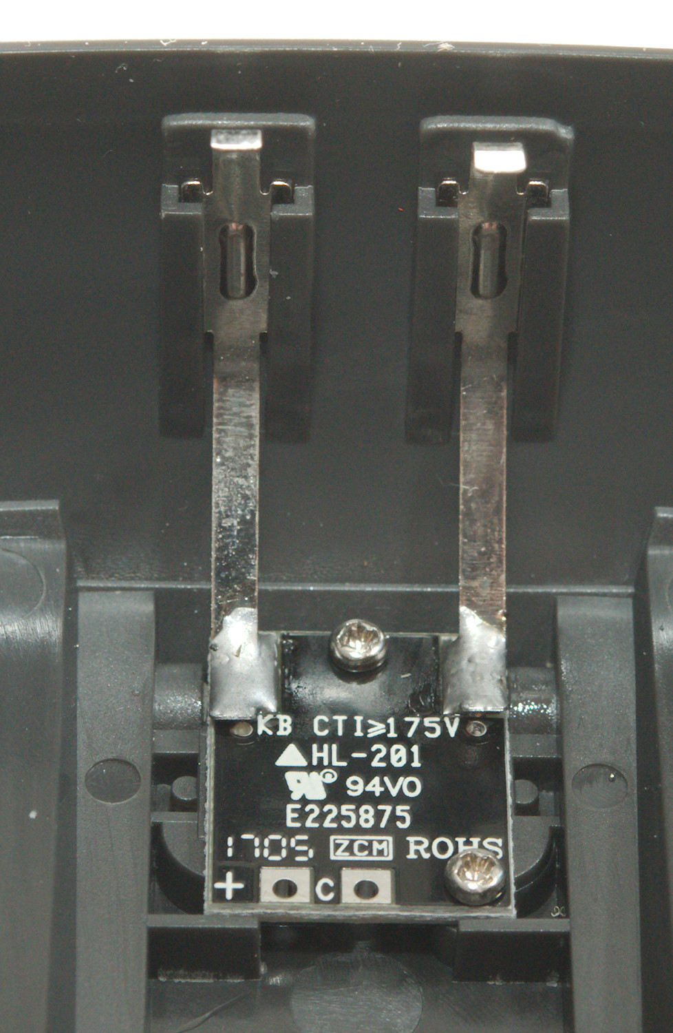
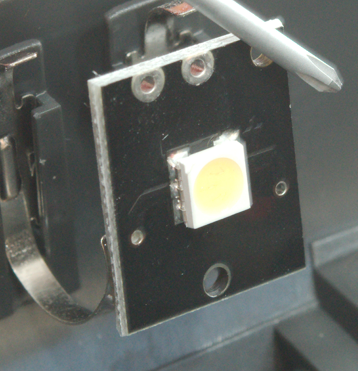
The flashlight is a small circuit board with metal strips working as spring connections to the main board. The circuit board only has the led on it, nothing else. The led contains 3 leds inside.
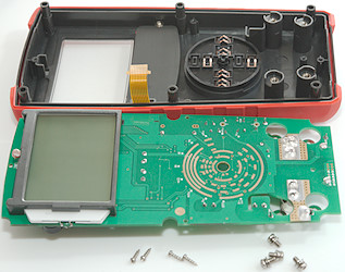
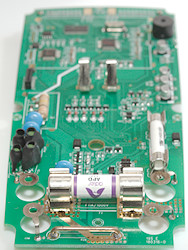
8 screws more (4 for the terminals and 4 smaller screws for the circuit board) and I could remove the circuit board.

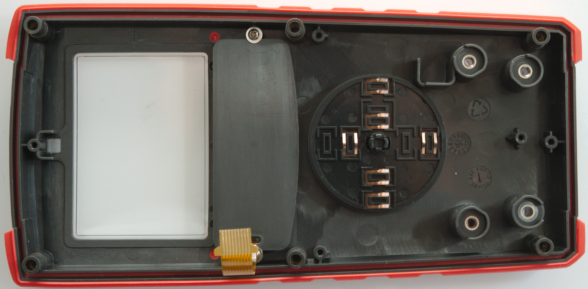
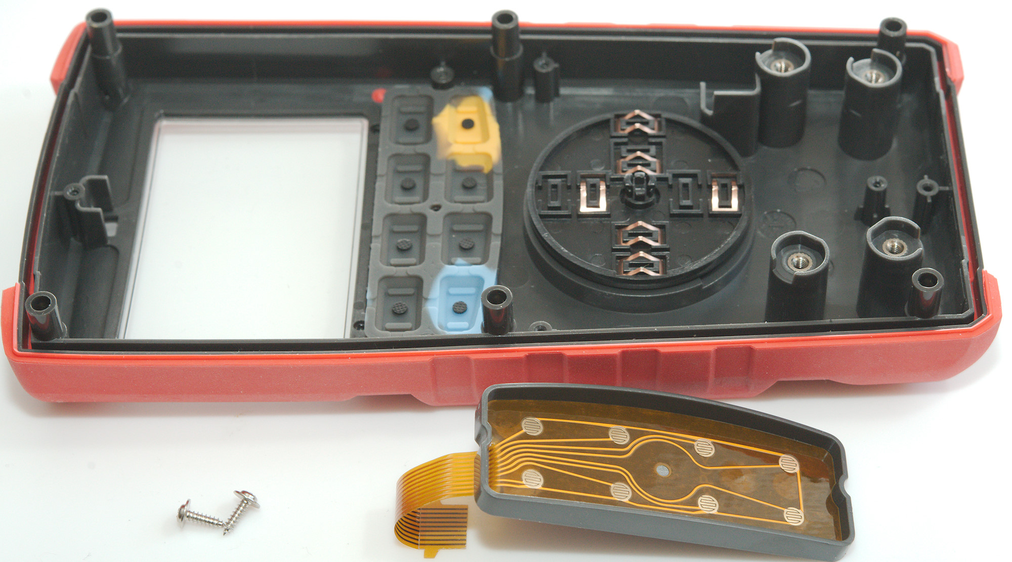
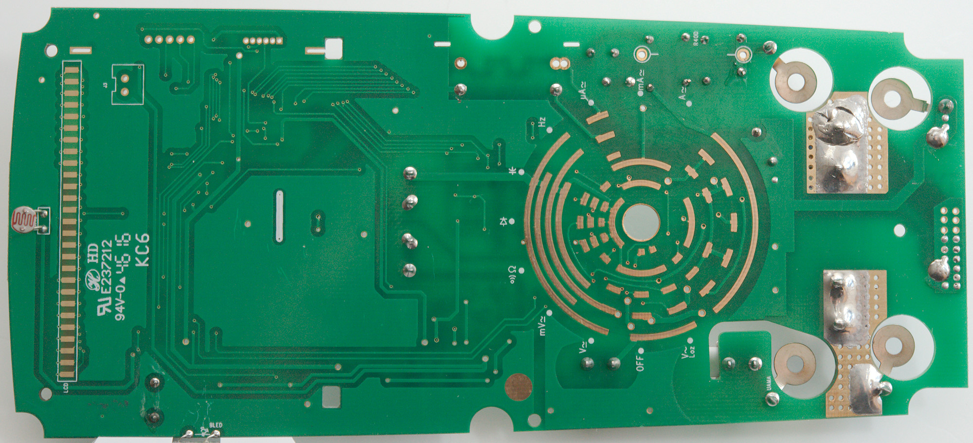
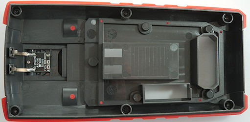
There is not the usual pads for buttons on the circuit board, instead a flat flex wire comes from the front.
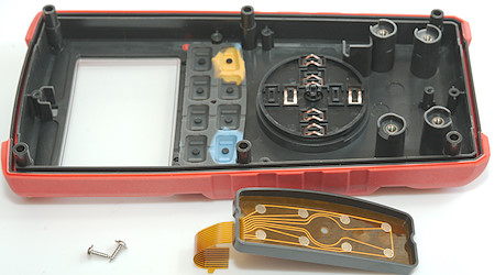
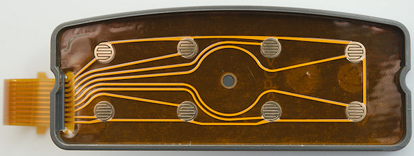
A flexible circuit board is used for the switch pads.
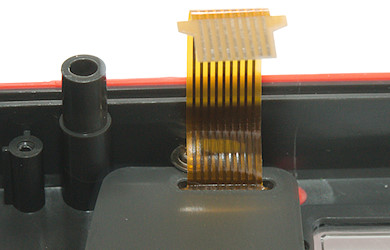
The wires to the backlight is a bit close, I will snip a mm off them before putting the meter together again.

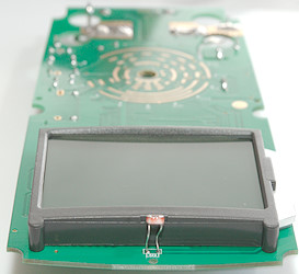
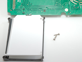
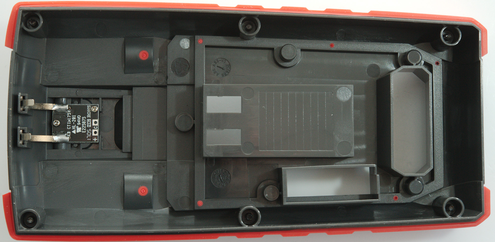
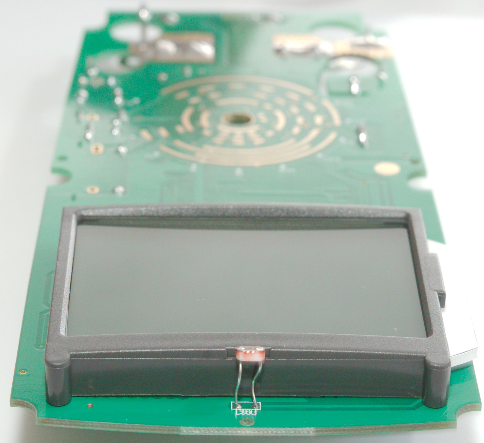
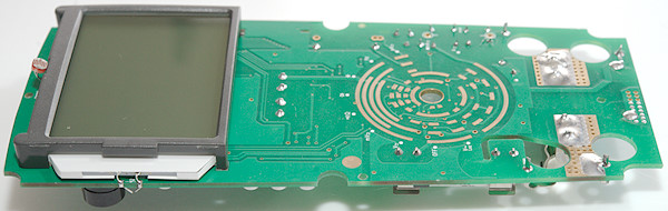
Two screws and I could remove the display.

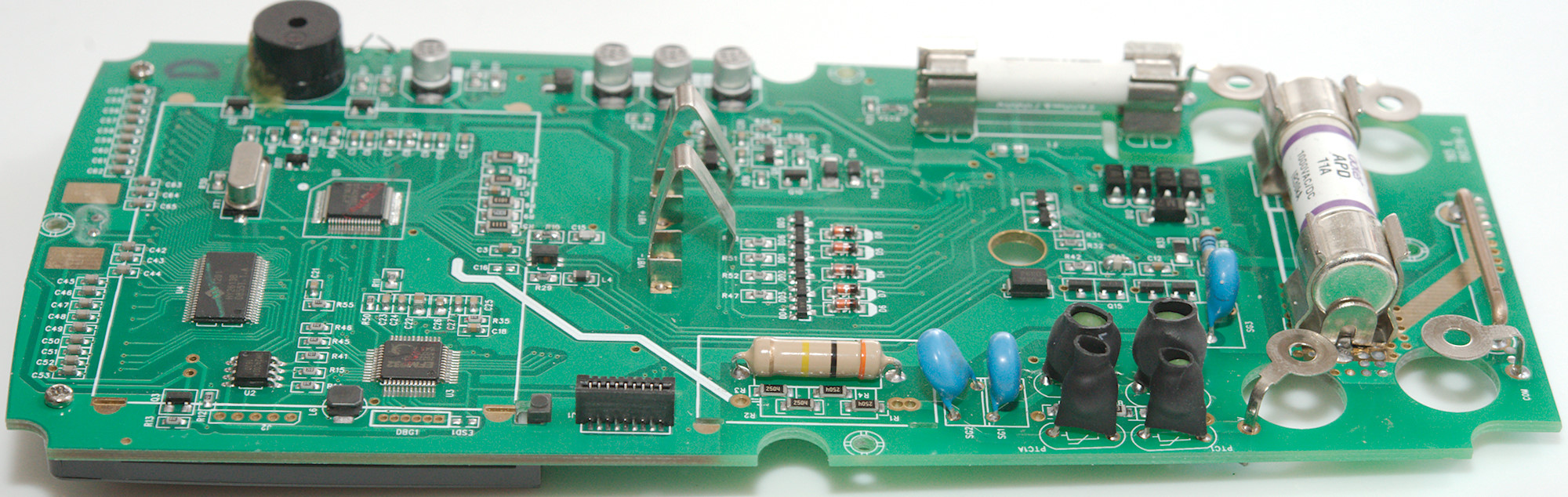
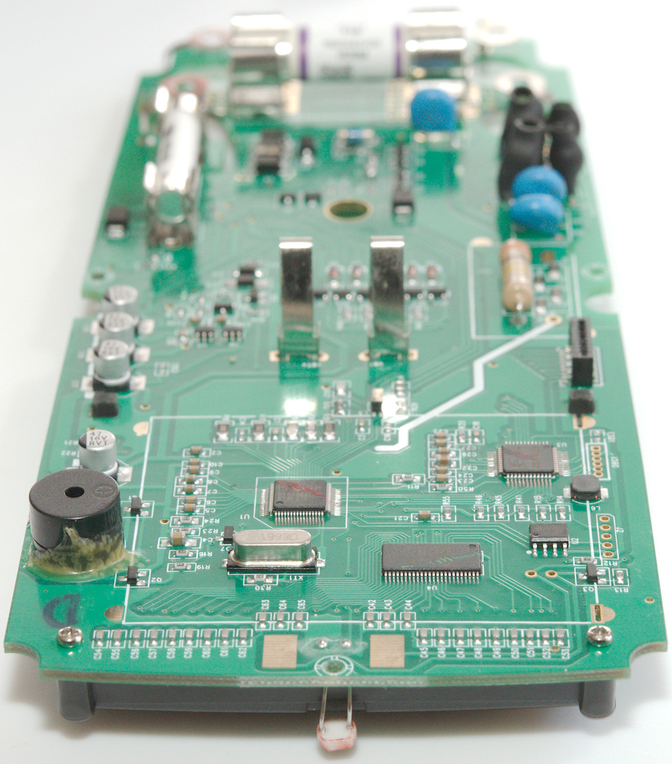
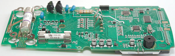
There is not much on this side of the circuit board. A LDR for automatic backlight control, a cut-out at the mA input terminal and the usual pads for range switch and display zebra stribe.
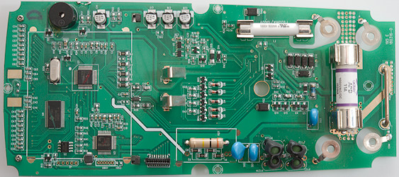
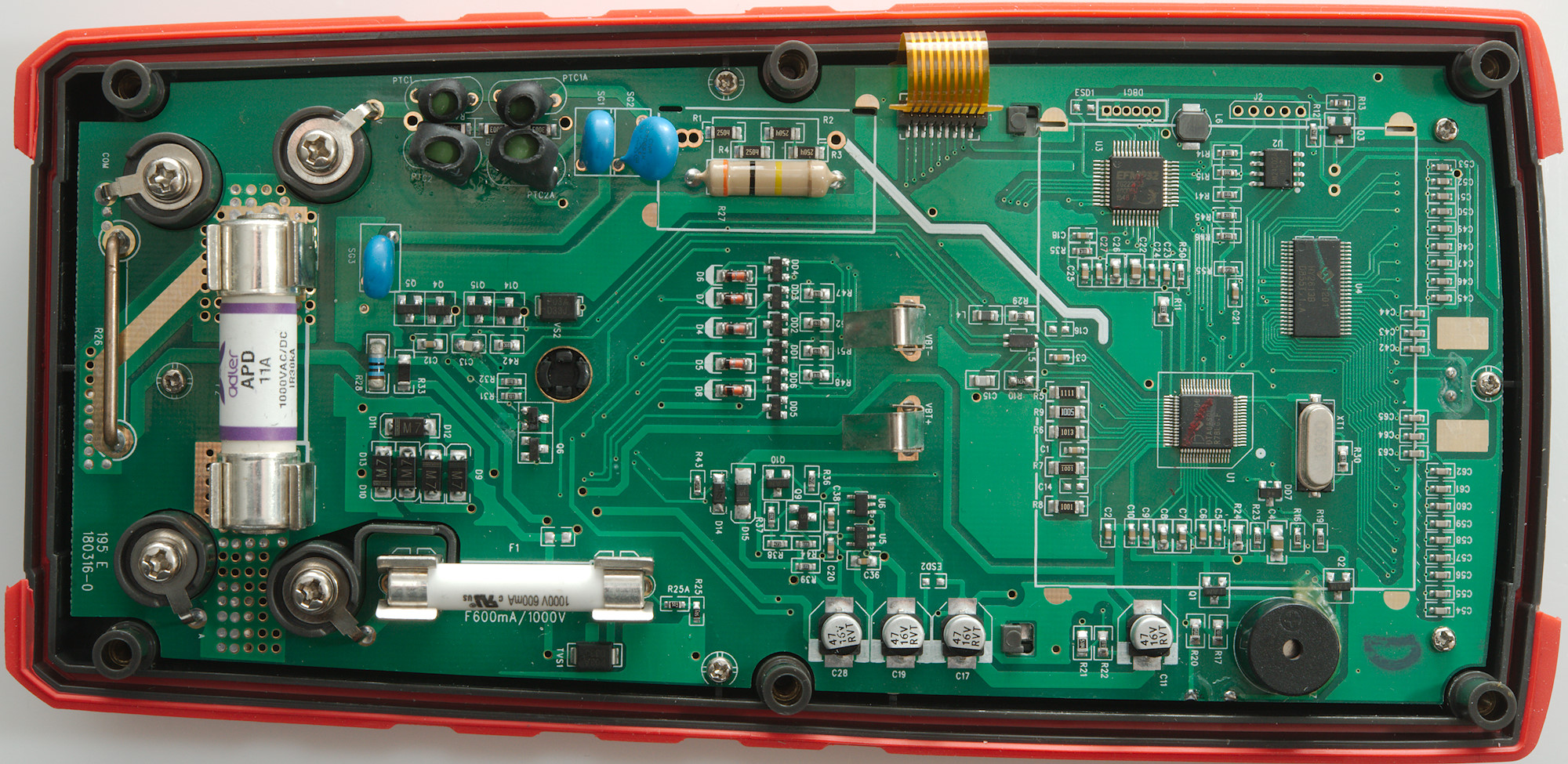
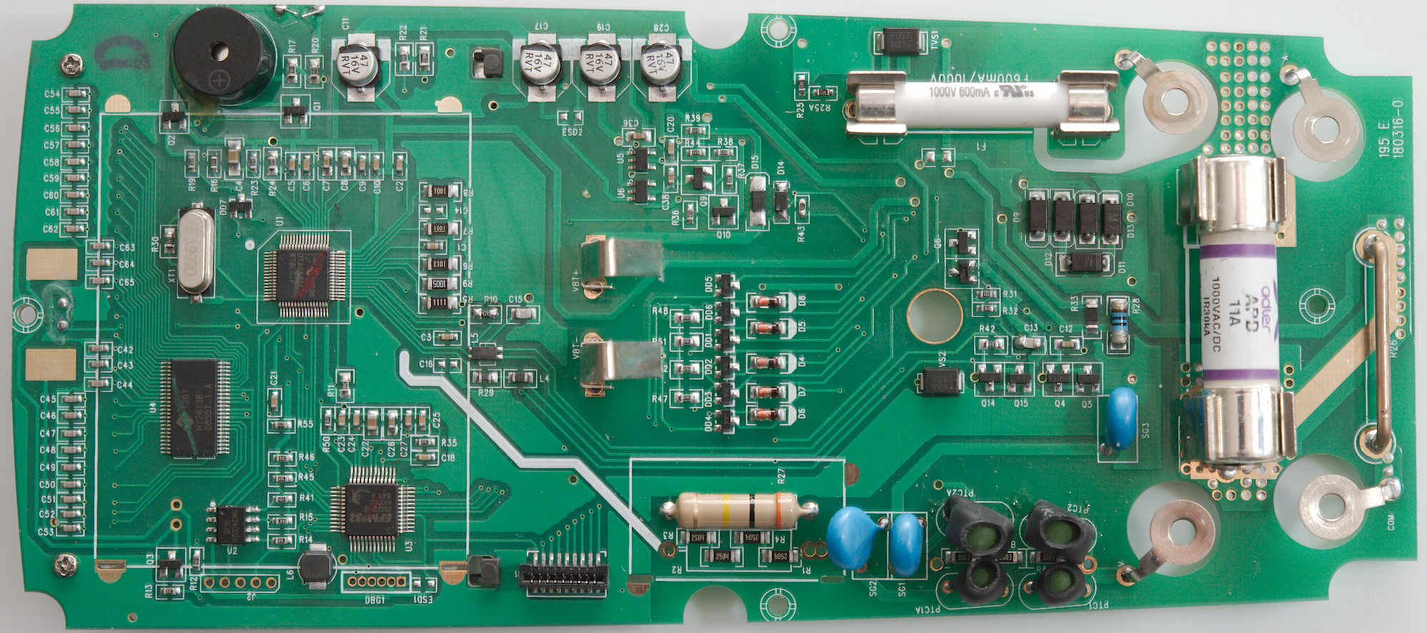
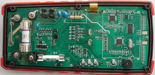
The voltage input has 3 tracks, two with PTC's (PTC1 & PTC1A and PTC2 & PTC2A) and one with resistors (R40A, R40B, R40C: 3x300Kohm) mounted between the PTC's. The two trakcs with PTC's are protected with MOV's (SG1, SG2, SG3). There is also some transistor pairs for protection: mV range (Q14 & Q15), diode (Q6 & Q?), ohm and capacitance (Q4 & Q5). The voltage input resistor (R1..R4: 4x2.5Mohm) is mounted after the MOV's, besides the LowZ resistor (R27: 300Kohm)
The current ranges has a A shunt (R26, probably 0.01ohm), a mA shunt (R28: 1ohm) and a uA shunt (R33: 99ohm). The diodes (D9.. D13) protect the mA resistors until the fuse blows. The uA resistor is protected by a transient voltage suppression diode (TVS1).
My guess is that all the diodes (DD1..DD6 & D4..D8) is used for encoding range switch position to one of the chips.
The area around U5 & U6 is the internal 3.3V power supply.
The multimeter is (U1: DTA0660L) with calibration EEPROM (U2: DM24C02A), this is controlled from a ARM processor (U3: EFM32ZG222F32, 32kB flash, 4kB ram), there is also a LCD driver (U4: HY2613B 4x36) for handling the display.

Conclusion
This meter has a lot of protection, i.e. the CAT rating is probably correct.
This meter has a good selection of ranges and functions for a standard multimeter with the addition of LowZ and flashlight. The automatic backlight looks like a useful feature.
This meter looks to be a rather robust meter with a simple user interface (Most functions on the range switch are directly selected and no secondary functions on the buttons).
Notes
UNI-T do often make rebranded meters, i.e. it may exist with other names on it.
How do I review a DMM
More DMM reviews