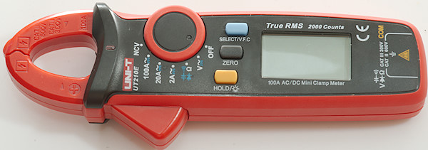
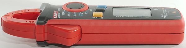
DMM UNI-T UT210E
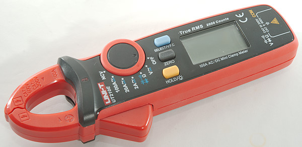
This is a cheap clamp meter with DMM function.
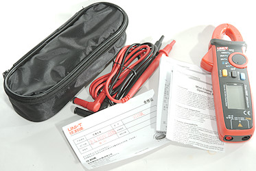
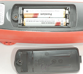
It included the DMM, a pair of probes, a pouch and a manual (Both a English and a Chinese version).
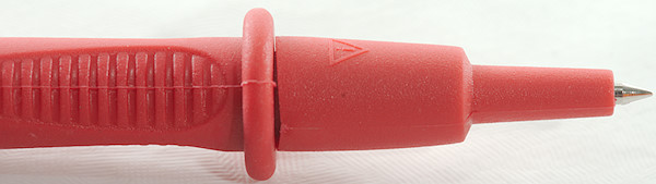
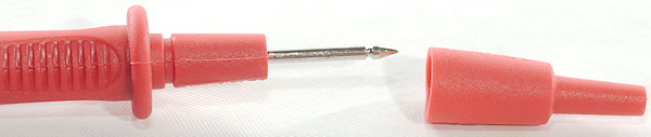
The probes has removable tip covers.
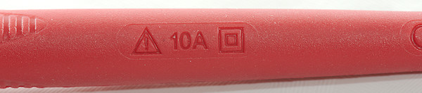
The probes are rated for 10A, but it is not important for a clamp meter.
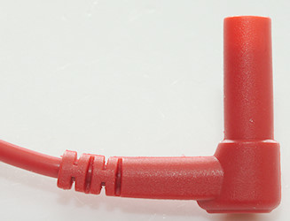
The plug is fully shrouded.
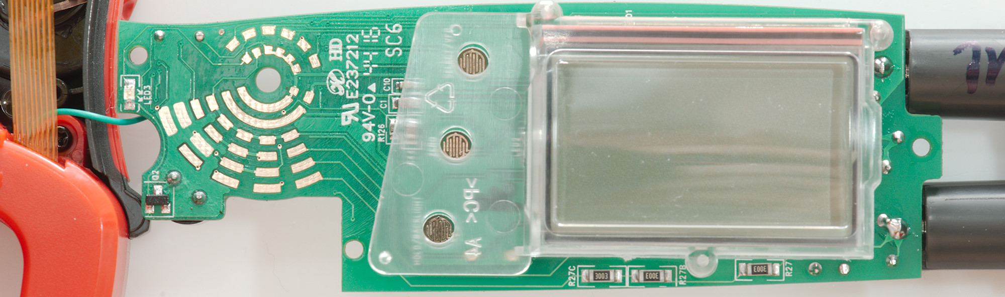
Display
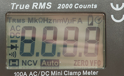
The above picture shows all the segments on the display.
The circle with the arrow indicates auto power off, holding down the SELECT button during power on will disable that.
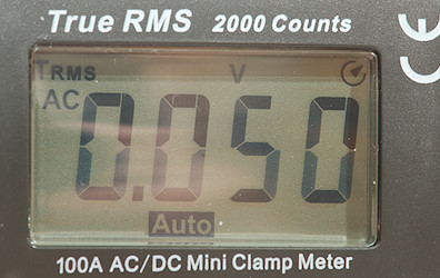
Typical display during usage, it will show the number and what measurement is selected.
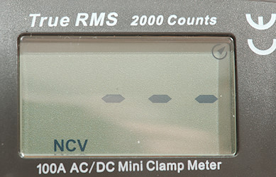
When using the NCV function the display will show a number of -, depending on the electric field. This can usual be used to see if a mains outlet or cable is powered or trace a cable that is just under the wall. This function is always a guideline and not a 100% confirmation of voltage or no voltage.
Functions
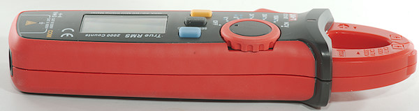
Buttons:
- Select/VFC (Blue): Will select secondary functions, holding down the button will enable a low pass filter for AC measurement (VFC).
- Zero: Save the current measurement and show the following measurements relative to that value (Very important for DC clamps).
- Hold (Yellow): Freeze the display, hold down to turn background light on.
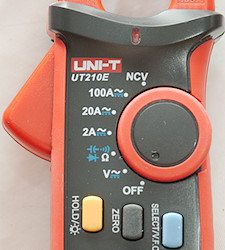
Rotary switch:
- Off: Meter is turned off
- V: Show voltage, use the blue button to select between AC and DC
- Ohm: Resistance, continuity, diode and capacitance
- 2A: Measure current with the clamp, use the blue button to select between AC and DC. Zero must be used on DC range
- 20A: Measure current with the clamp, use the blue button to select between AC and DC. Zero must be used on DC range
- 100A: Measure current with the clamp, use the blue button to select between AC and DC. Zero must be used on DC range
- NCV: Non contact voltage. Any AC field near the clamp will be indicated.
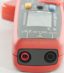
Input
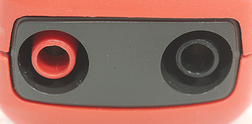
The two socket is used for V, Resistance, continuity, diode and capacitance
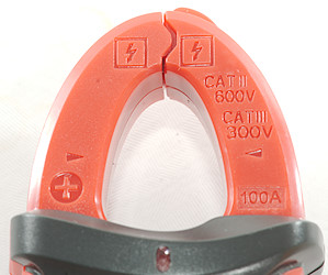
The clamp is used for all current measurements and for NCV. There is a red led at the bottom of the clamp to show when voltage is detected with the NCV function (Buzzer will also sound).
Measurements
- Volt and frequency
- 1 VAC is 5% down at 2kHz (RMS will not work at the frequency).
- AC volt with VFC reduces bandwidth to 400Hz and limits range to 200.0V & 600V
- All ranges starts on AC
- Input impedance is 10Mohm to 11Mohm on AC and DC
- Buzzer sounds on over voltage (600V)
- Voltage input is rated for 600V DC/AC
- Current
- Buzzer sounds on over current (100A).
- All ranges starts on AC
- As usual clamp meters are not very precise and at 0.5A and 5A it was about 2% out.
- Clamp is rated for maximum 100A
- Ohm, Continuity, diode and capacitance
- Ohm needs about 2.6s to measure 100ohm
- Ohm is 1.0V open and 0.33mA shorted
- Continuity is very fast (Below 4ms).
- Continuity beeps when resistance is below 50ohm.
- Continuity is 1.0V open and 0.33mA shorted
- Diode range uses 3.3V, max. display is 2.2V at 0.5mA, max. current is 1.4mA shorted
- 11000uF takes about 9 seconds to measure.
- Input is rated for 600V DC/AC overload.
- Miscellaneous
- Current consumption of meter is 7.2mA (13.2mA with backlight) in current mode
- Current consumption of meter is about 1.7mA (7.7mA with backlight) in other modes.
- Meter works down to 2.2V where it turns off, battery symbol show at 2.5V.
- Backlight only works down to about 2.6V where it is fairly dim.
- Both current and voltage readings are stable with changing battery voltage.
- The meter usual need a couple of display update to reach the final value.
- Viewing angle is good.
- Display updates around 3 times/sec
- Backlight will automatic turn off in about 15 seconds.
- Will automatic turn power off in about 15 minutes.
- Weight is 174g without accessories, but with batteries.
- Size is 174 x 62 x 32mm
- Probes & clamp
- Probe resistance 37mOhm for one.
- Probe wire is 90cm long.
- Clamp can handle up to ø17mm
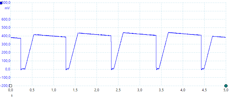
A look at the capacitance measurement waveform.
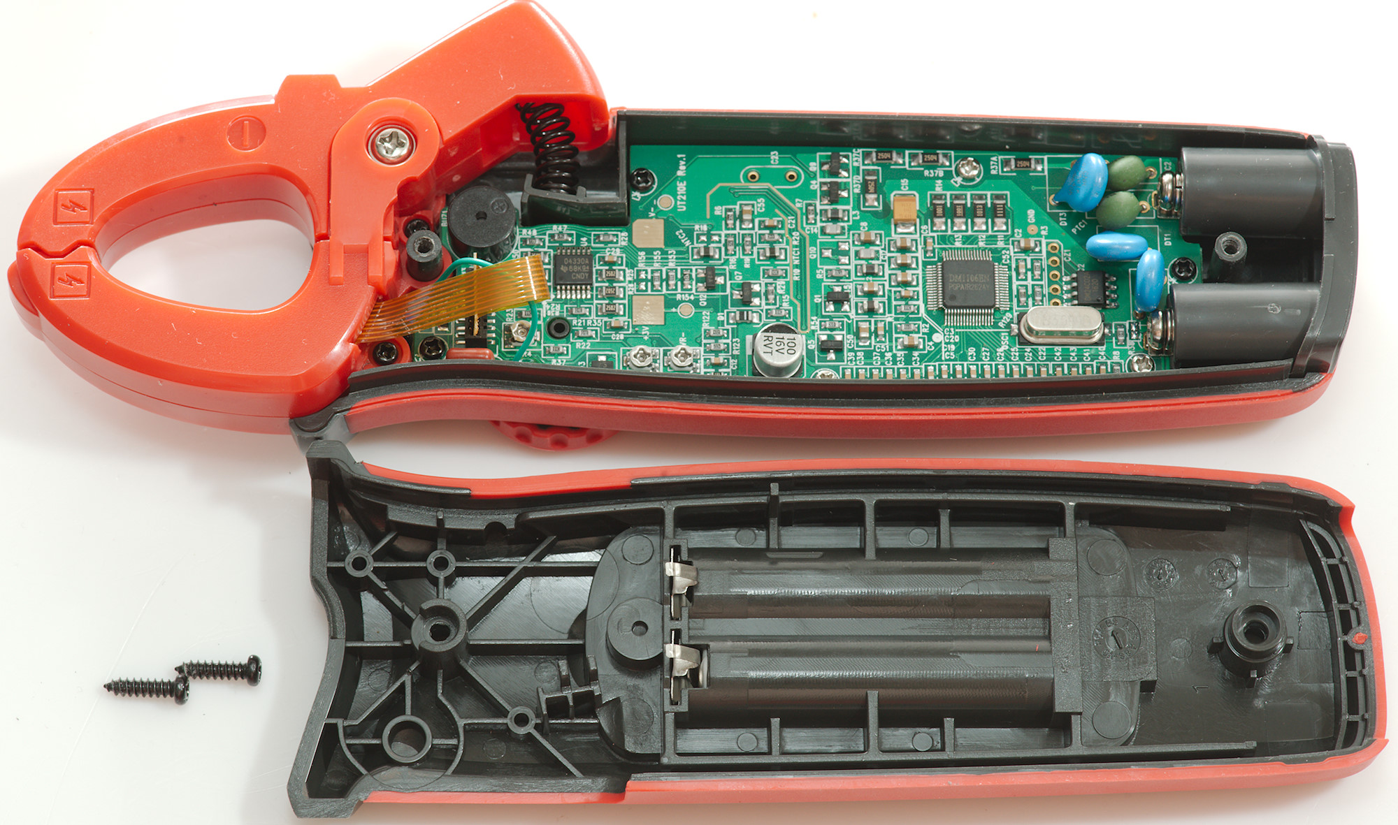
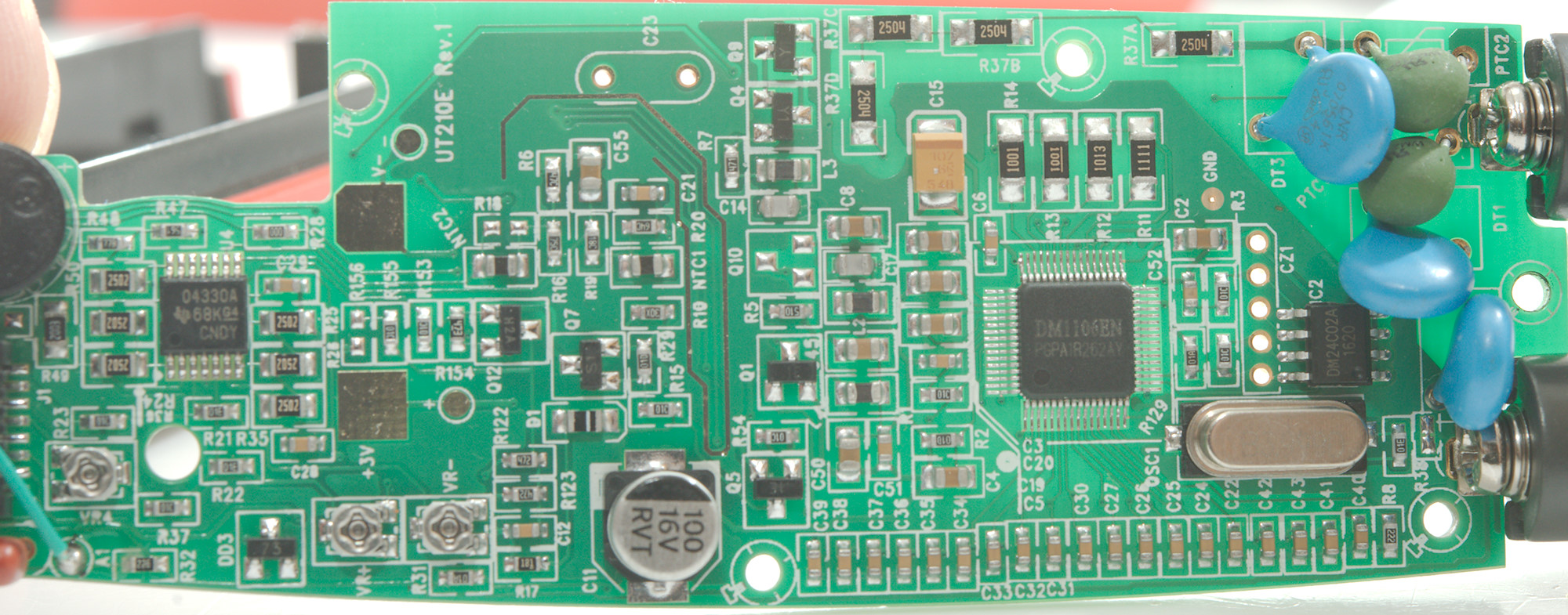
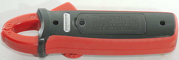
Tear down
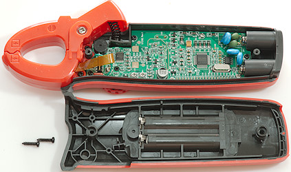
I had to remove two screws to open the meter.
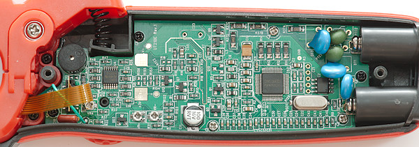
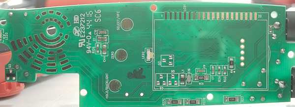
The circuit board is carefully made to fit inside the meter and use all aviable space.
I assume the green wire is the NCV sensor
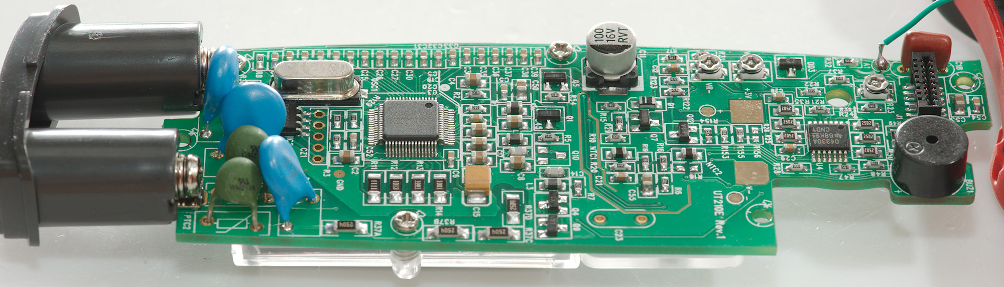
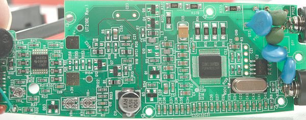
The circuit board has some input protection with two PTC's and 3 MOV's. The input resistors (R37A, R37B, R37C, R37D: 4x2.5Mohm) is split into 4 resistors, between these resistors and the input is a PTC.
Close to the MOV's is a EEPROM (IC2: 24C02A) for parameter storage and some calibration, there is also trimpots for calibration.
There is a voltage clamp made with two transistors (Q4, Q9), it is not directly connected to input or output resistors but is probably switched in depending on range.
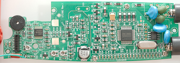
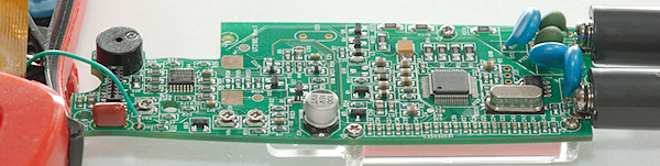
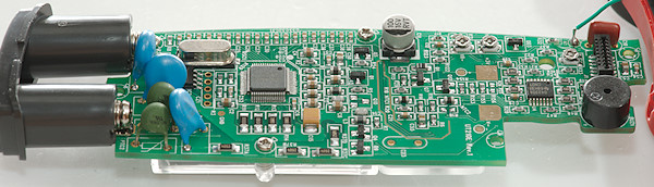
The big IC (DM1106EN) is the main multimeter chip and the frontend for the clamp is mounted close to it (U4:OPA4330 Quad OpAmp).
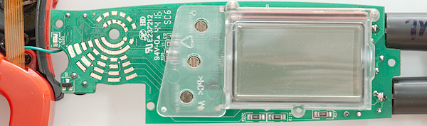
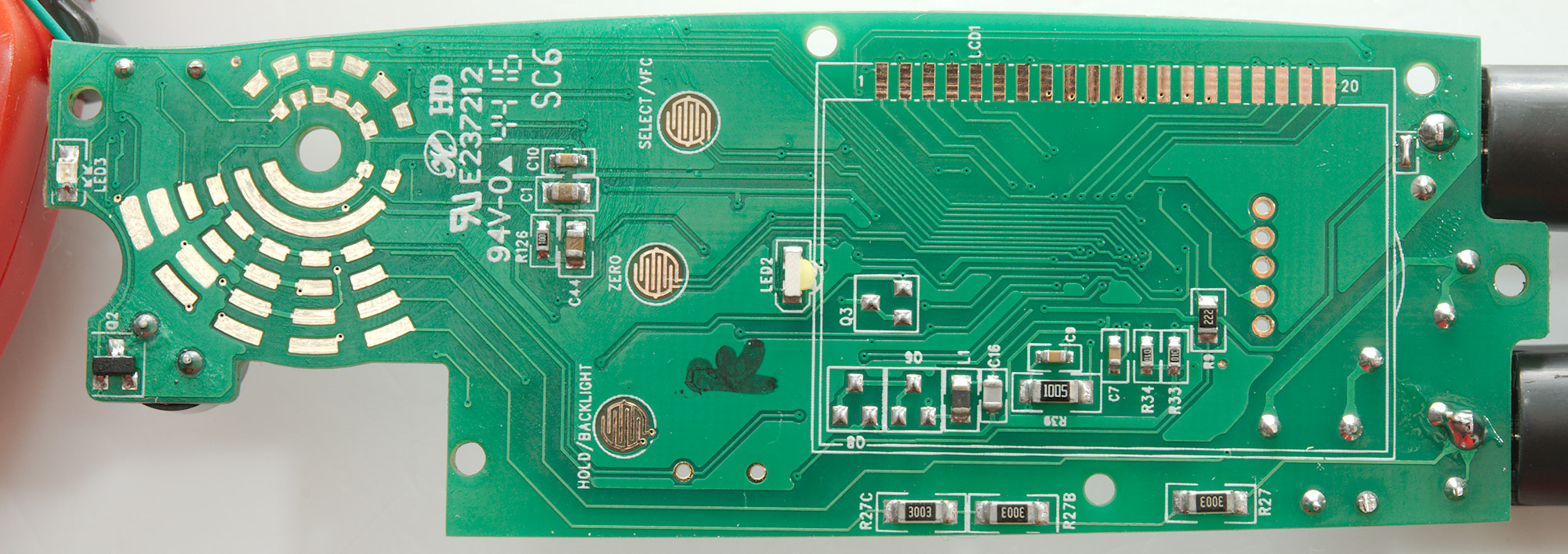
One this side is another string of resistors (R27A, R27B, R27C: 3x300kohm), but strange enough they are connected directly to the input terminal without any protection. The NCV voltage led (LED3) and the transistor to drive it (Q2) is also placed here.
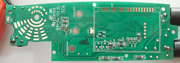
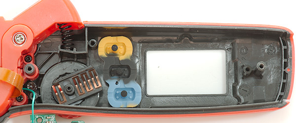
There is also space for unused protection (Q6 & Q8). The backlight led is a side emitting led (LED2) mounted at the border of the LCD display.
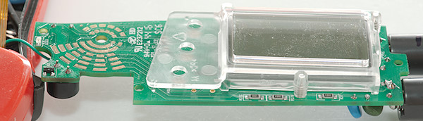
The pink zebra stripe that connects the display to the circuit board can be seen here.
Some backlight on the circuit board makes it easier to see the traces.
Conclusion
This meter is nice for measuring 100's of mA or more without any voltage drop, using it for lower DC currents requires careful use of the zero button.
It has basic DMM functions, but it missing frequency and low currents.
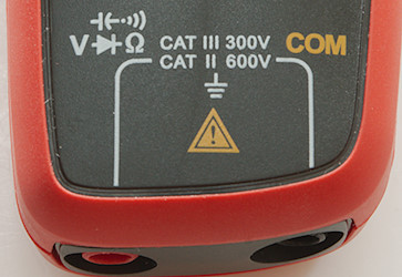
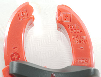
It looks like it has real input protection and the CAT rating may be correct.
Notes
How do I review a DMM