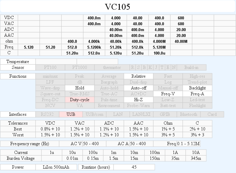
DMM VC105
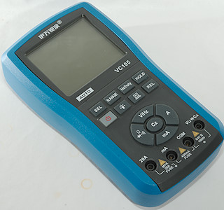
This meter do not have a normal range switch, but uses buttons for selecting range. It is equipped with usb rechargeable batteries and the specifications say that it is more or less waterproof.
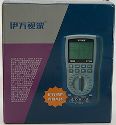
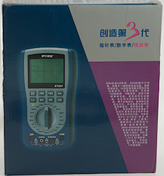
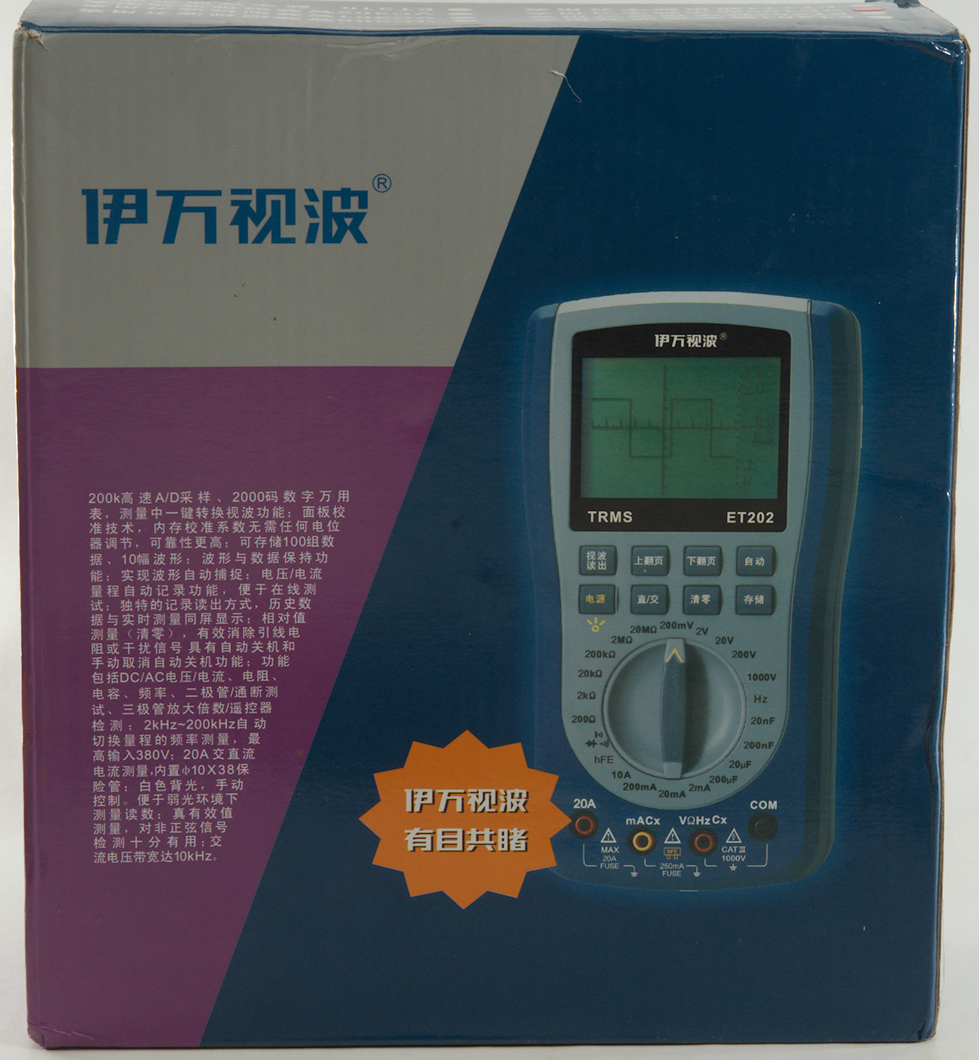
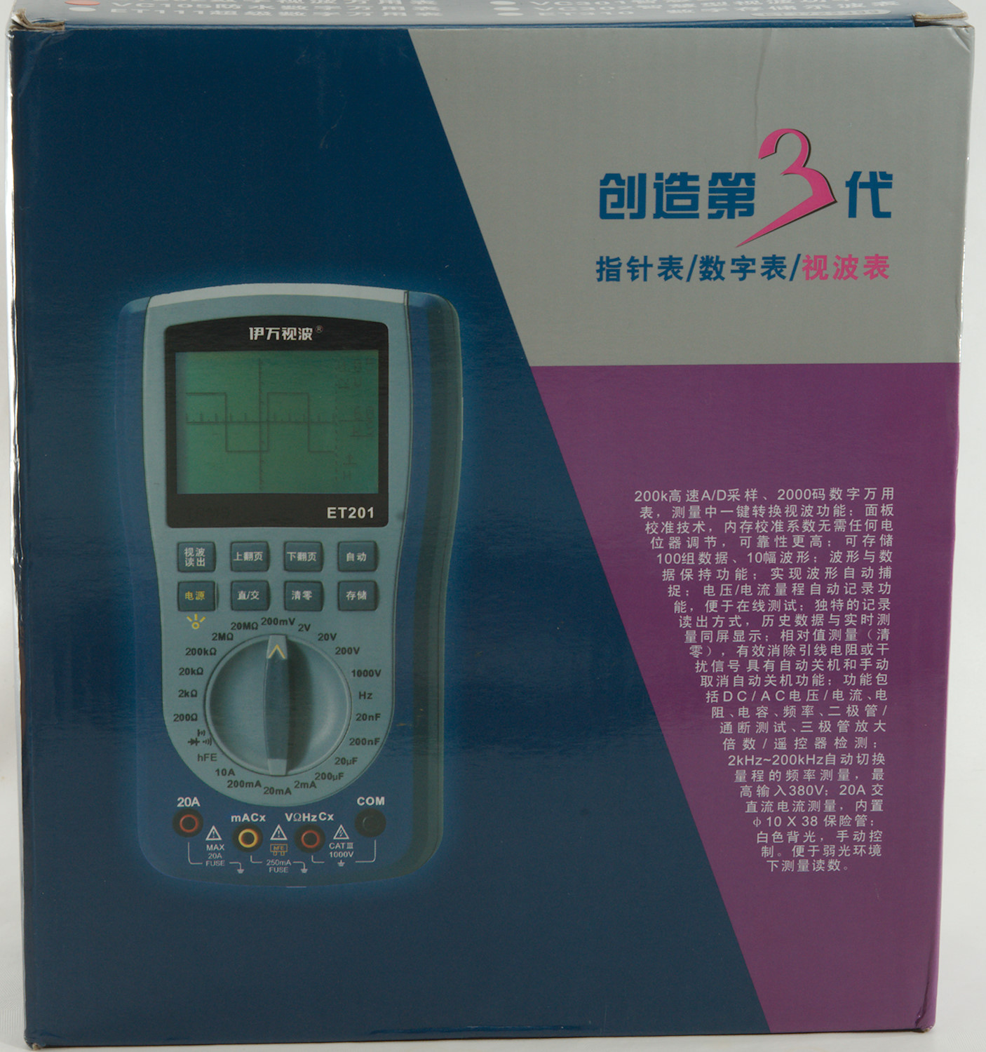
The box depicts another meter.
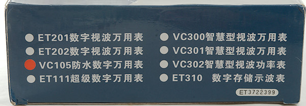
But at the bottom the correct type is checked.
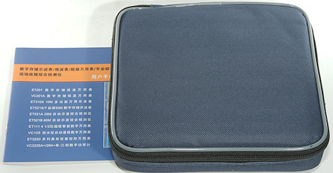
The box contains the Chinese manual and a pouch with the multimeter.
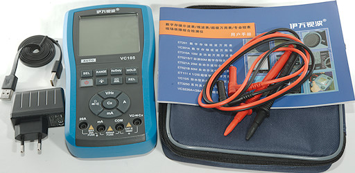
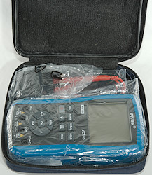
The total contents is the multimeter, two probes, Chinese manual (It is possible to download a English manual), pouch, usb cable A-A, power supply/charger.
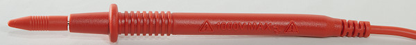
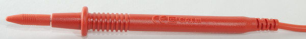
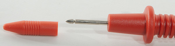
The probes specify CAT III 1000V rating, but that is not possible without tip cover. At best they are CAT II 1000V.
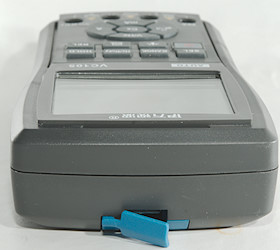
The plug is fully shrouded and nearly standard size.
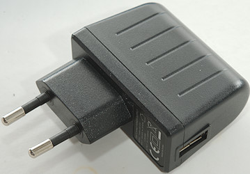
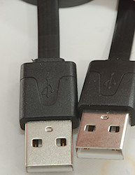
A standard usb power supply, but a non-standard cable with two usb-A connectors.
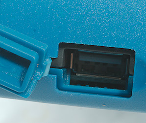
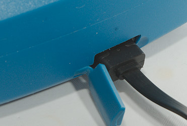
The meter has a hole where it can be plugged in, this is a very unsafe solution (Meter do not have galvanic isolation).
Manual do warn against charging from a computer while doing measurements.
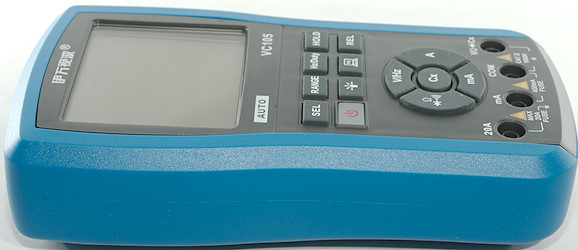
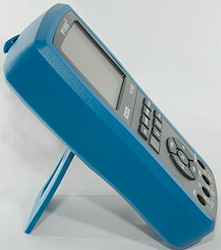
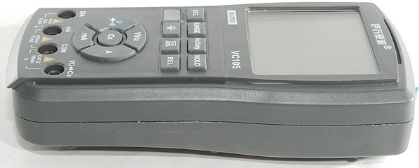
The buttons can be used with the meter standing.
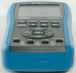
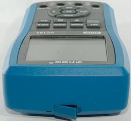
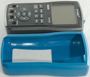
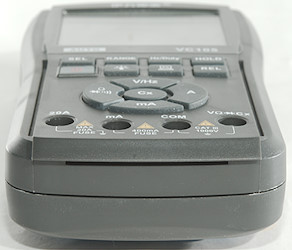
Meter is not designed for use without the sleeve.
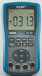
Display
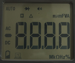
For the size the display is fairly simple.
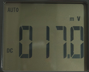
During use it will show the selected range and the value.
Functions
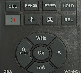
Buttons:
- Sel: Select between DC/AC and ohm/diode/continuity
- Range: Select manual range and change range (Must be used for mVAC), hold down to reactivate auto ranging.
- Hz/Duty: Switch to frequency and duty-cycle in voltage and current modes.
- Hold: Freeze the display.
 : Power button, a press will turn on the meter, hold down to turn off.
 : Background light on/off
 : Computer interface, requires special cable and software and may be dangerous to use.
- Rel: Remember the current reading and show all new readings relative to it.
- V/Hz: Voltage display, use SEL for AC and Hz/Duty for frequency.
- A: Ampere range, use SEL for AC.
- mA: Milliampere range, use SEL for AC.
 : Ohm, Diode and Continuity, use SEL for selection.
- Cx: capacitance range, this is always auto ranging.
Input
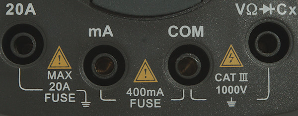
- 20A: High current, it is possible to use 20A for 30 seconds
- mA: The lower current ranges.
- CON: The common terminal for all ranges.
- xxx: All other ranges.
Measurements
- Volt and frequency
- At 100mVrms in DC frequency input range is from 0.5Hz to 2kHz
- At 1Vrms in DC frequency input range is from 0.4Hz to 22kHz
- At 4Vrms in DC frequency input range is from 0.4Hz to 3MHz
- Duty cycle works from 20% to 80% at 1kHz with 4Vpp, precision is within 10.0 (This is just about useless)
- 1 VAC on AC input is 5% down at 2.3kHz
- Frequency counter requires a zero crossing.
- mVAC must be manually selected
- Input impedance is 10..11Mohm.
- mV DC range is high impedance up to around 1.5 volt where it slowly drops to 10MOhm
- Over voltage protection is 600VAC/VDC
- Current
- 400mA current is protected by a 0.4A/250V 5x20mm fuse.
- 10A current is protected by a 20A/500V 10.3x38mm fuse (Fuse is marked 1000V).
- Manual specifies not to use current ranges above 250VAC
- Ohm, Continuity, diode and capacitance
- Ohm needs about 3.8s to measure 100ohm
- Ohm is 0.44V open and 0.17mA shorted
- Continuity is moderate speed (About 160ms).
- Continuity start beeping when resistance is below 75ohm and stops beeping when resistance is above 103ohm
- Continuity is 0.44V open and 0.17mA shorted
- Diode range uses 1.4V, max. display is 0.999V at 0.14mA, max. current is 0.5mA shorted.
- 10uF takes about than 2.5 second to measure.
- 100uF takes between 13 and 17 seconds to measure.
- Over voltage protection is 250VAC/VDC
- Miscellaneous
- Current consumption of meter is about 11mA, 17mA with backlight. The relay only need a current pulse to change and will not increase power consumption.
- Meter works down to 2.5V where it turns off, battery gauge shows empty at 3.3V.
- Reading do not change with battery voltage.
- Backlight varies with battery voltage and is very dim at 3V
- The meter needs many display update before it shows correct value.
- Viewing angle is good.
- Display updates around 2.5 times/sec
- Backlight do not automatic turn off, but turns off when the meter turns off.
- Auto turn off after about 13 minutes.
- Standard probes fits.
- Weight is 497g without accessories, but with sleeve and build-in LiIon battery.
- Size is 194 x 106 x 46mm with sleeve.
- Probes
- Probe resistance 49mOhm for one.
- Probe wire is soft and 75cm long.
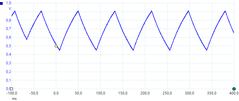
A look at the capacitance measurement waveform with a 1uF capacitor
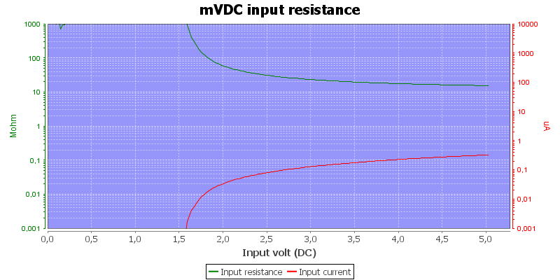
The input resistance in mVDC
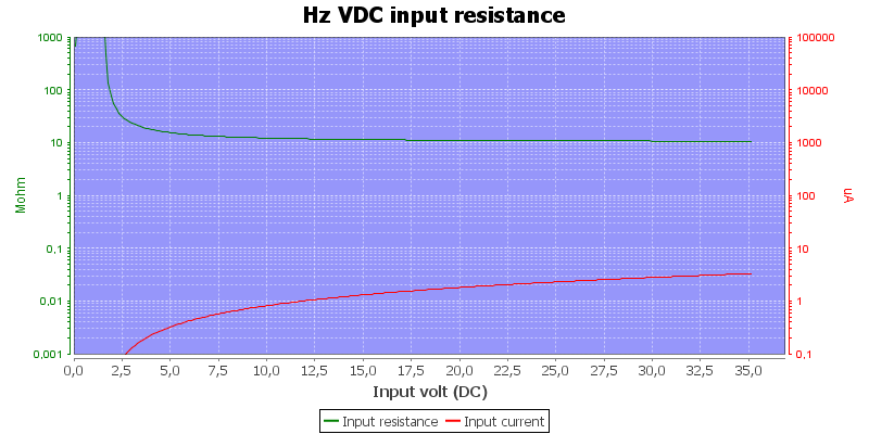
Frequency input is 10Mohm, except in mVDC range.
High DC voltage blocks for AC readings.
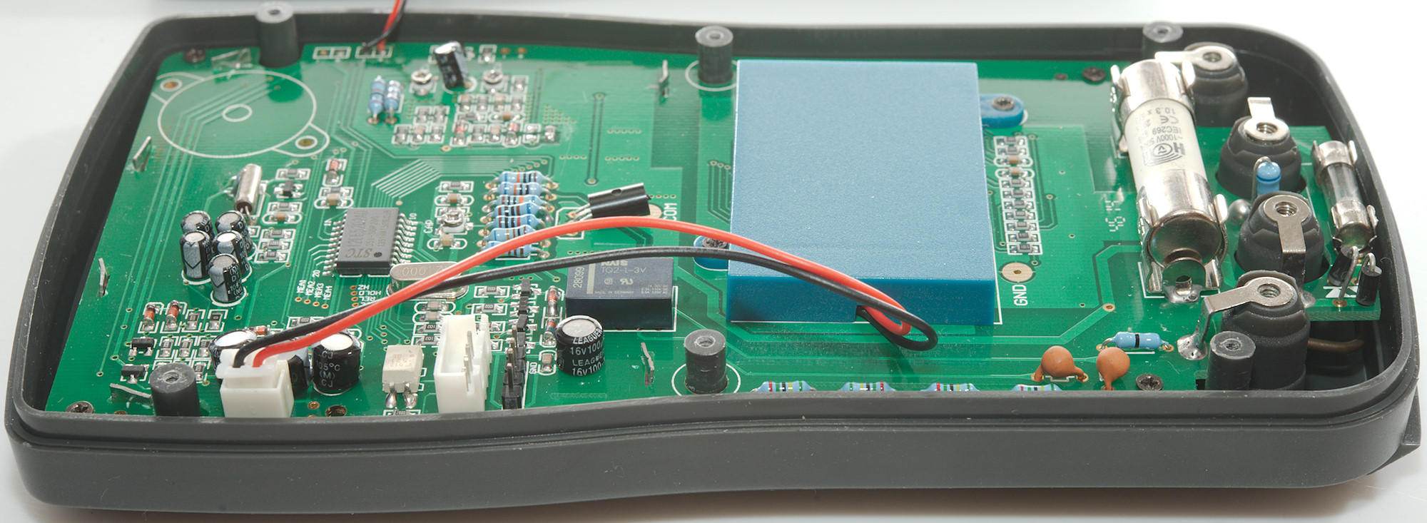
Power supply/charger
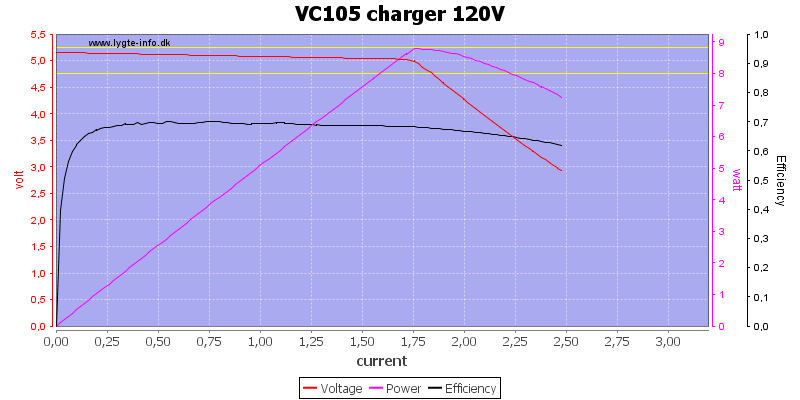
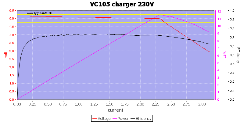
The power supply is rated 1.2A, but can deliver much more. I wonder if it is a over temperature cut-out. This will not be a problem as long as it is only used with the multimeter.
The power supply passed the 2830 volt and 4242 volt between mains and low volt side.
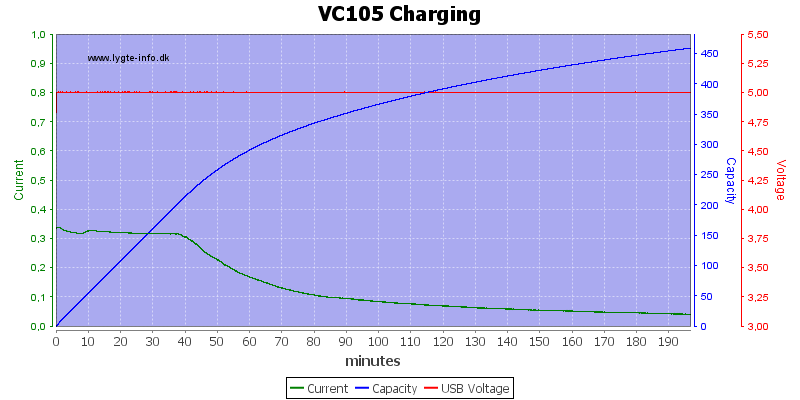
After running the battery down I tried charging. The charge current is fairly low, but the meter is more than half charged after 1 hour. I wonder if it really is 500mAh or only 350-400mAh.
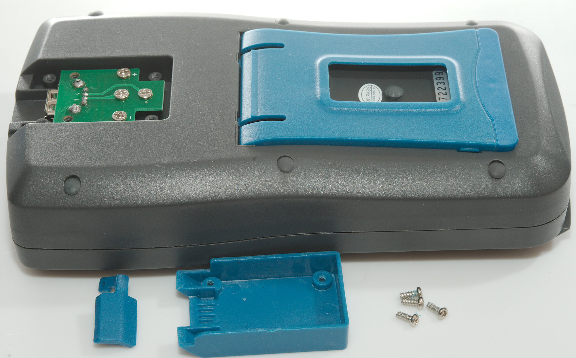
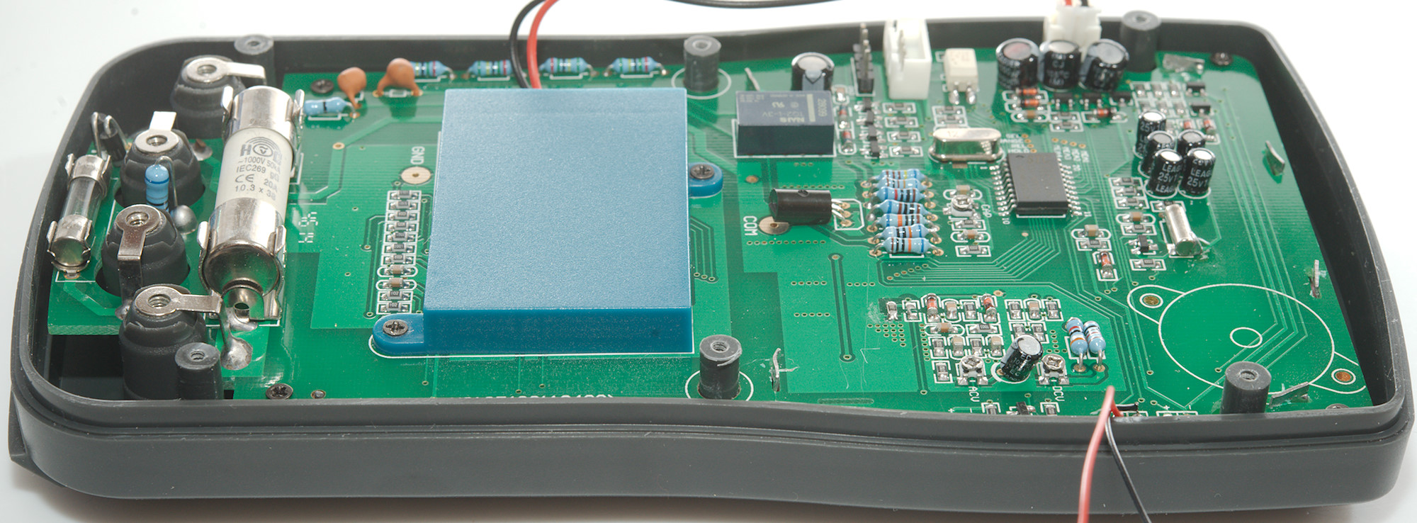
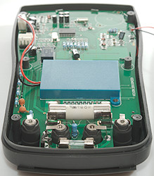
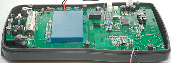
Tear down
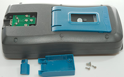
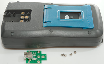
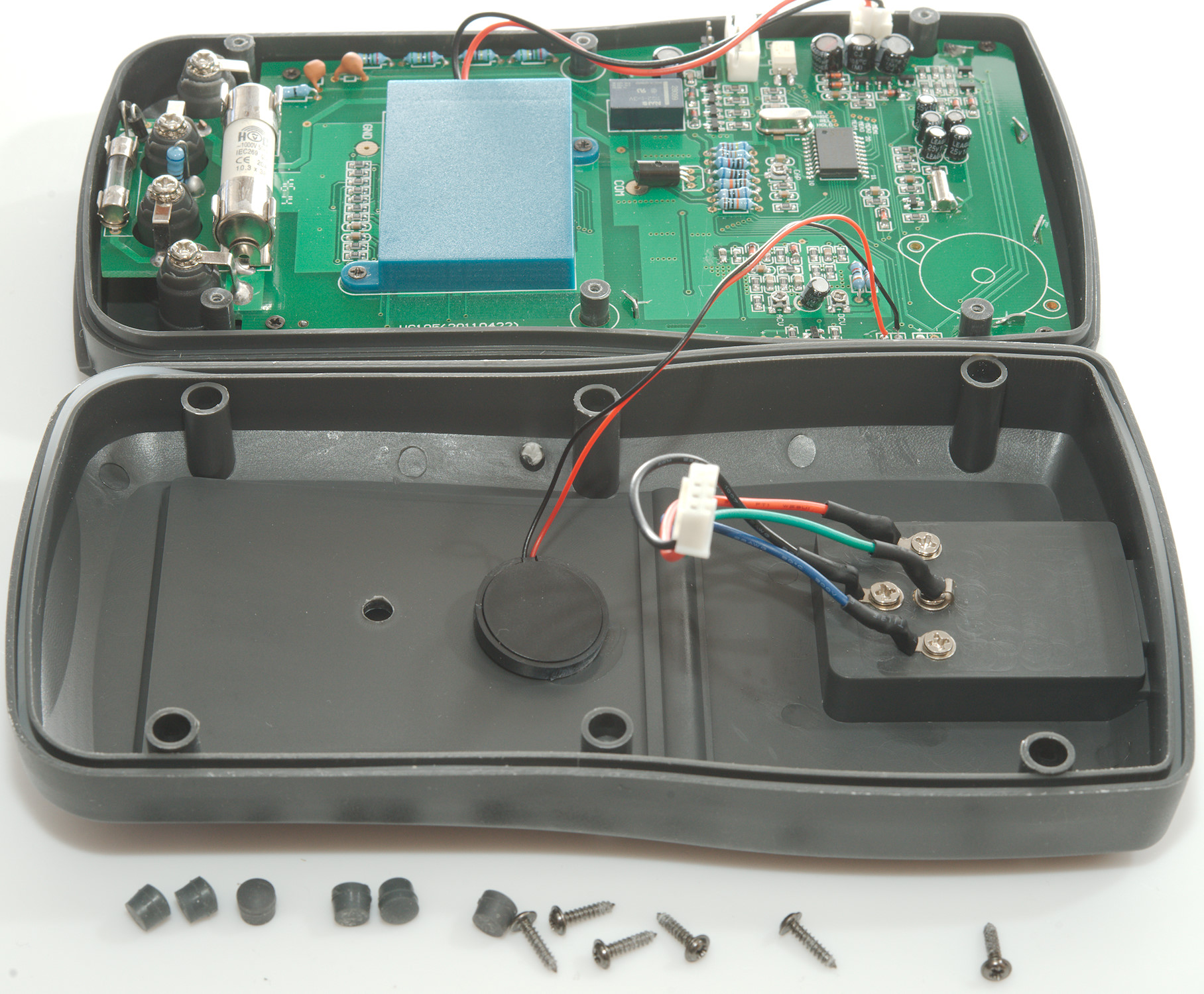
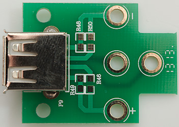
First a look at the usb connector, four screws to remove the cover and four screws to remove the circuit board.
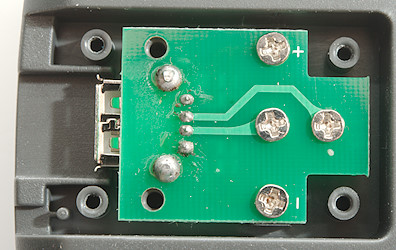
The four screws holding the circuit board all has electric connections.
The lid before the usb connector may not be waterproof, but the water will not get more into the meter this way.
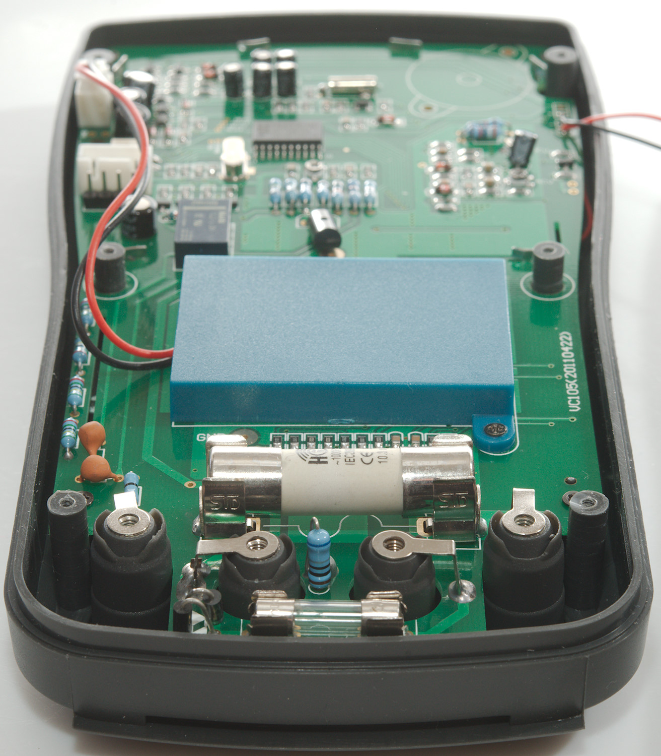
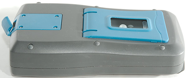
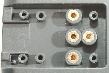
To open the meter I had to remove 6 rubber plugs, before I got access to the screws. There are 7 plugs, the last one was just a hole.
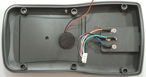
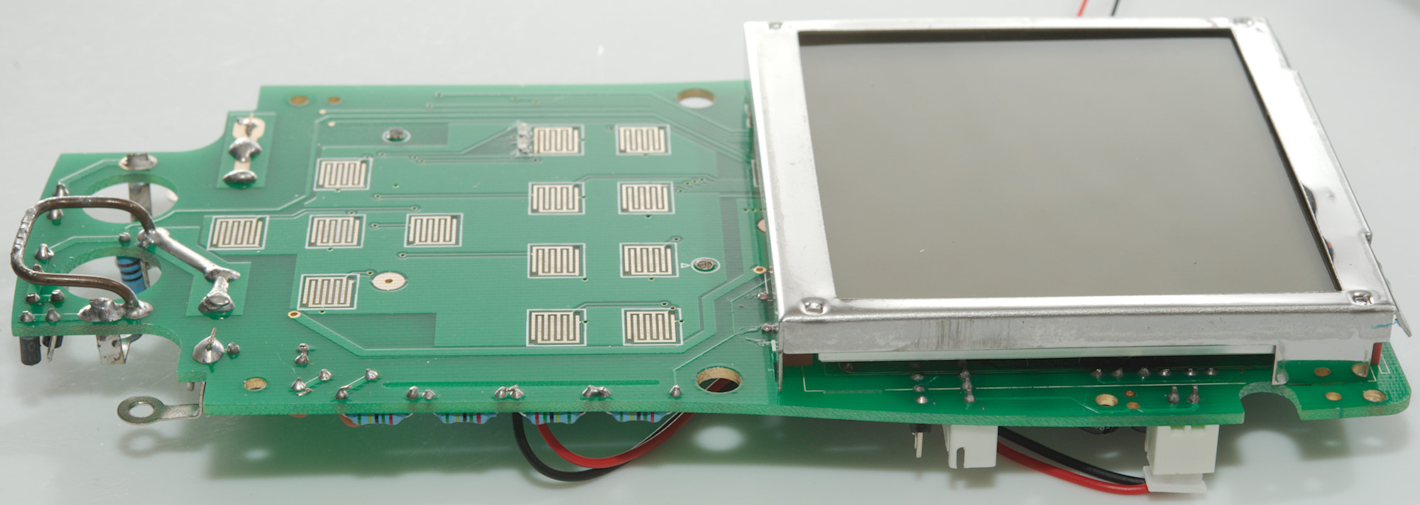
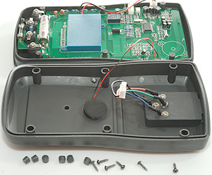
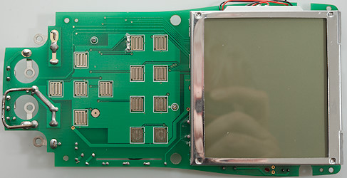
The buzzer is glued on the back and not mounted on the designated spot on the circuit board.
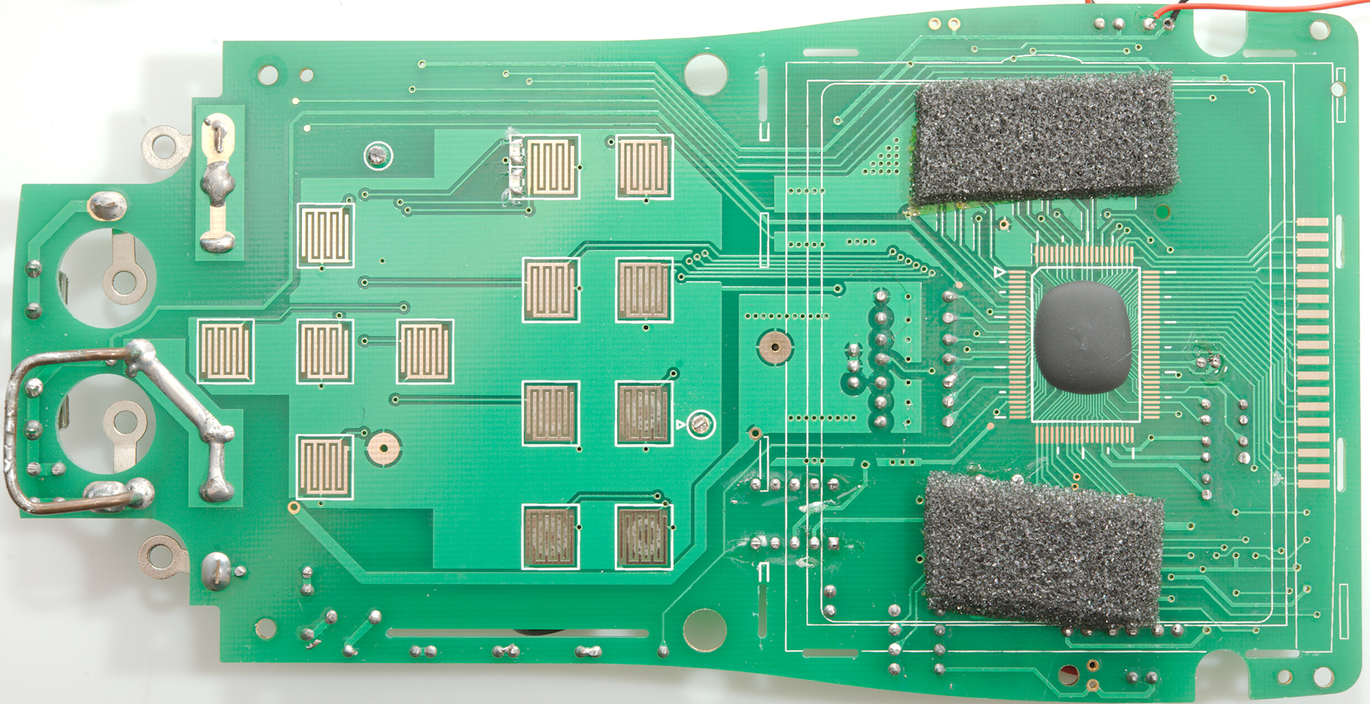
The 20A range has a large fuse, but the mA range only has a glass fuse, There is two diodes to protect the mA range (mounted next to the fuse), the resistor (1ohm) is mounted between the COM and mA terminals.
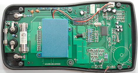
The voltage input has a zero ohm resistor before it splits into two PTC's in series, a 10Mohm path (4x2.5MOhm at the edge) and a 900kOhm path. The PTC and 900Kohm path is switched by the latching relay (Relay is rated for 750VAC breakdown, CAT III 1000V is 8000V spikes). The PTC path goes through the relay and then to the row of resistor with a transistor near COM on the circuit board.
It looks like the relay has 4 transistors and two diodes for the two coils.
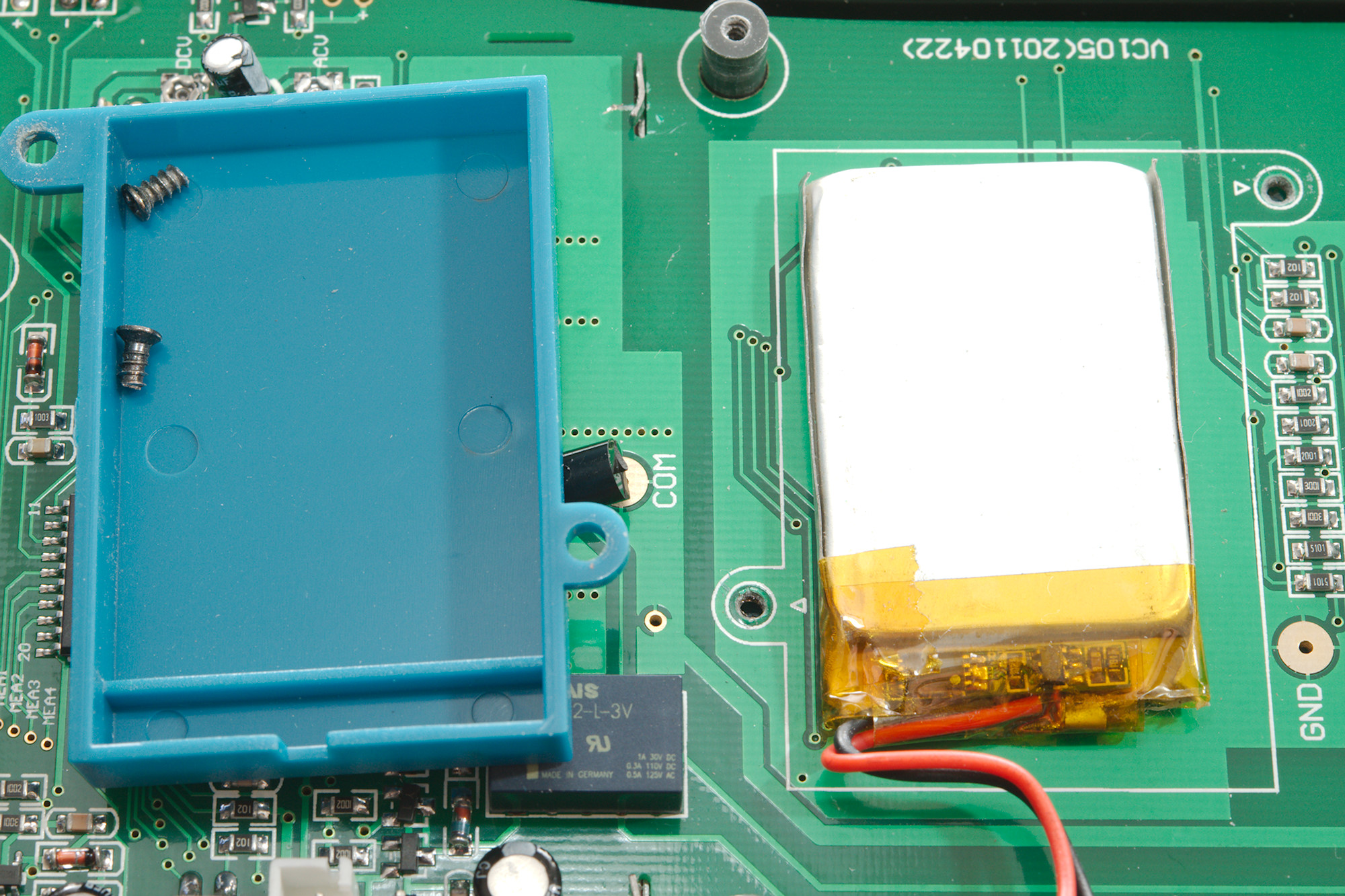
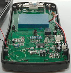
There is a microprocessor in in the meter (STC12LE5202AD 2Kflash 256bytes ram), it simulates the range switch for the DMM chip and handles the relay. Near the usb connector is a optocoupler, that is for the communication. Near the battery connection is two chips, one of them is probably the LiIon charge chip and the other a regulator for internal voltage.
There is 3 trimpots with labeling.
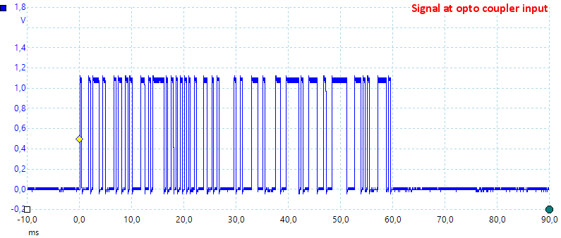
Here it is, it looks like around 2400baud and is probably segment information (I have not tried to decode it). Even though the signal is on the usb connector it is not usb. A special cable is requires to use this signal, i.e. converter it to a usb signal.
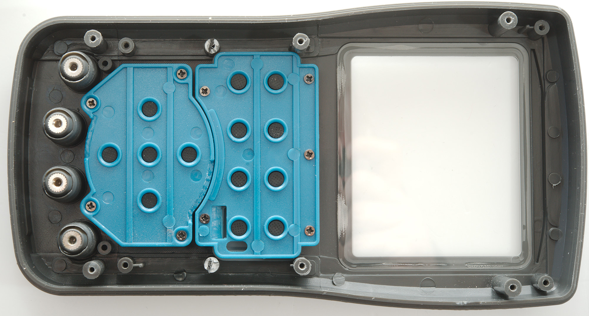
Four screws for the terminals and for screws four the circuit board and I could remove it from the meter.
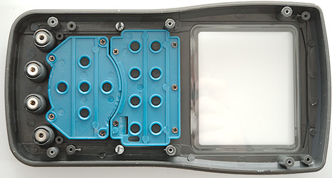
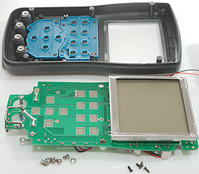
There is done something for the switches to make the water resistant.
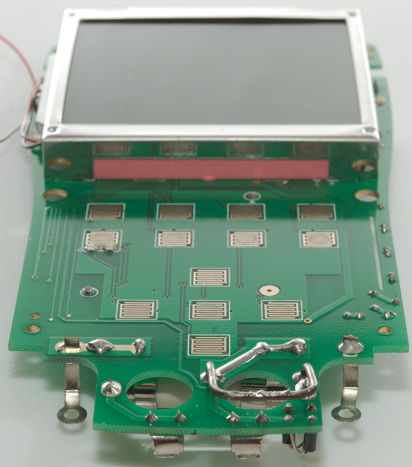
This meter do not have a range switch, just more pads for push buttons. The 20A shunt is also on this side.

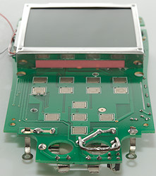
To remove the display I had to untwist some metal tabs.
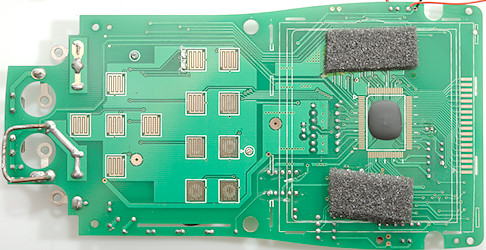
The multimeter chip is hidden below the display.

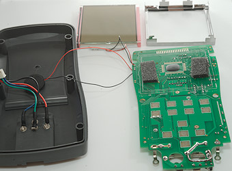
The display is damaged where the metal tabs are twisted, I expect this is from the original manufacturing, but it did make me nervous about putting it back together again. I could hear some glass getting crunched when I twisted the metal tabs to lock the display, but it worked without any missing segments.
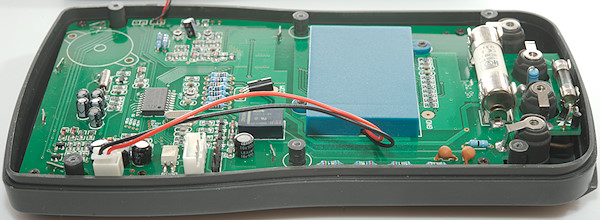
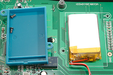

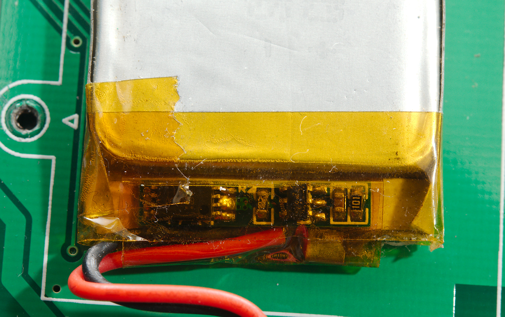
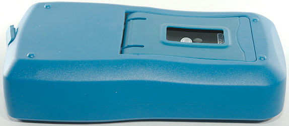
Inside the battery box was a normal small LiIon cell with a protection circuit. I could not read the numbers on it.
Conclusion
Safety is a joke with this meter, on the front is printed CAT III 1000V, but the manual says maximum is 600V on voltage and 250V on current. The usb connector is not isolated from the test leads input.
For normal measuring it works fine, but it missing uA, capacitance only goes to 100uF, there is no min/max or temperature and duty cycle is not really usable. This means it is a fairly basic meter, but it probably handles splashes fairly well, except the usb connector.
Notes
How do I review a DMM
More DMM reviews