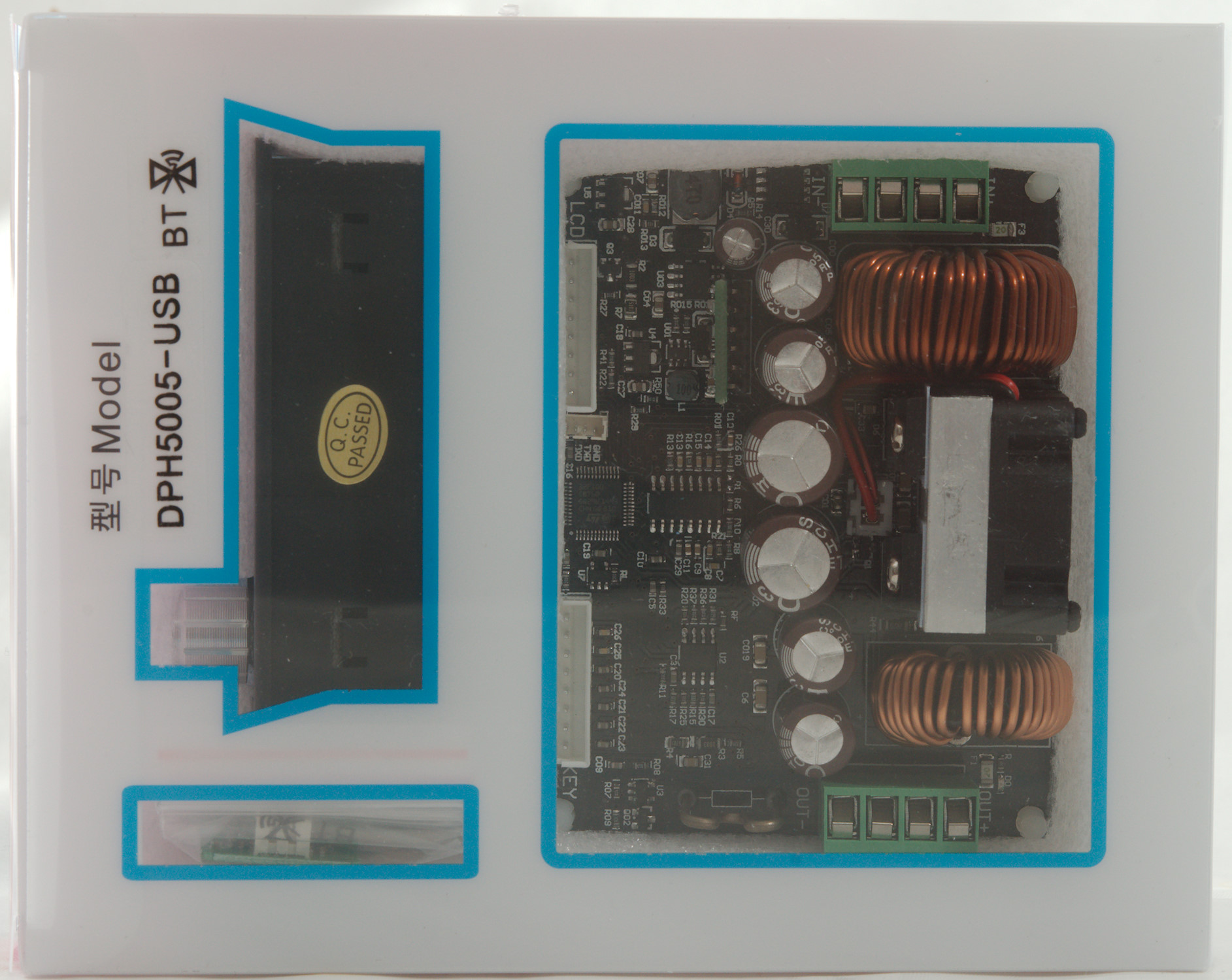
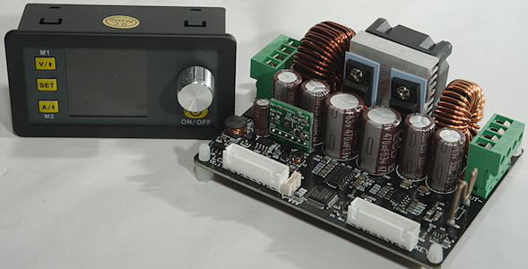
Power supply frontend DPH5005-USB 50V/5A with Bluetooth and USB interface
This device is the front end for a power supply, it must be supplied with low voltage DC power (Up to 50V).
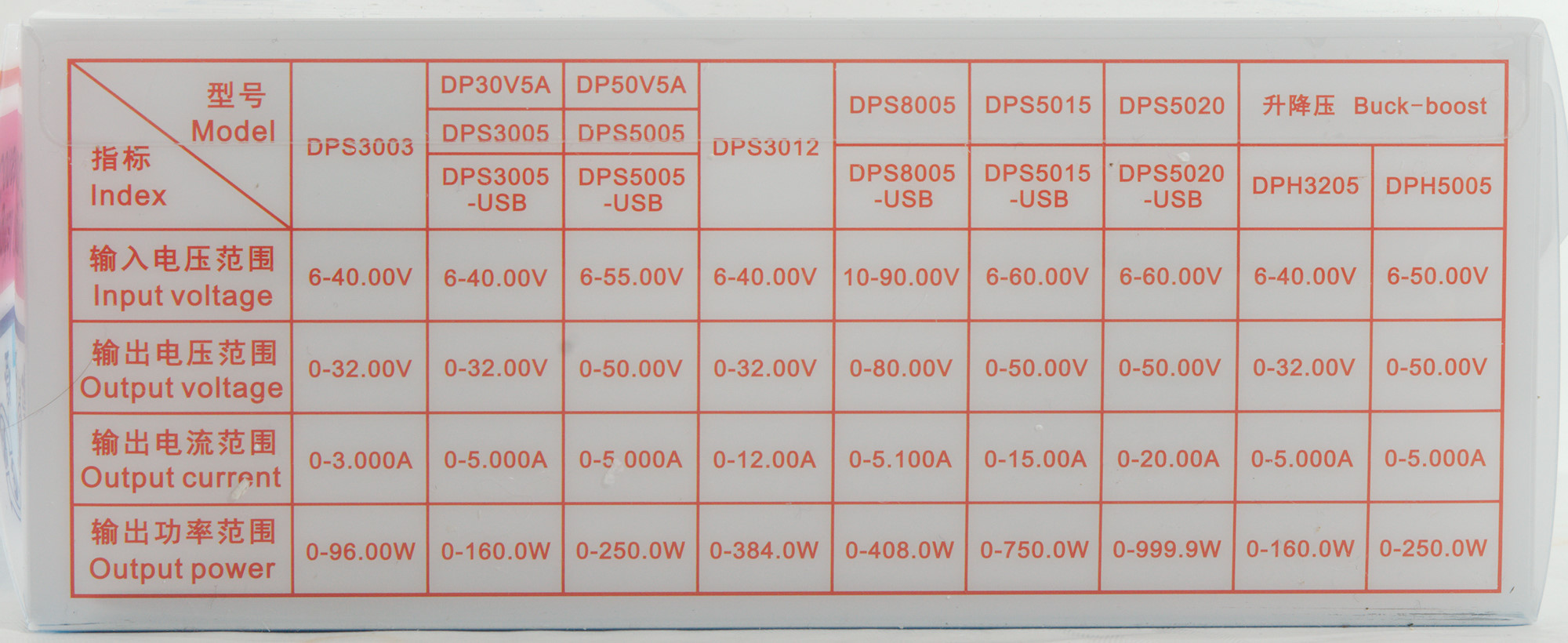
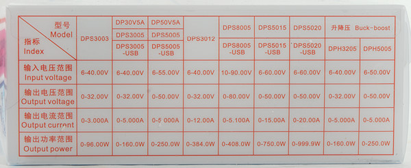
Official specifications:
- Input voltage range: 6.00-50.00V
- Output voltage range: 0V-50.00V
- Output current: 0-5.00A
- Output power range: 0-250W
- Product Weight: about 222g
- Display module size: 79*43*38(mm) (L*W*H)
- Cutout size: 71mm*39mm
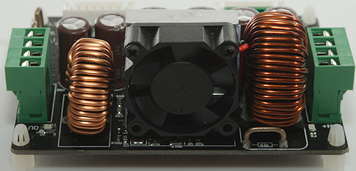
- Power module size: 93*71*41(mm) (L*W*H)
- Length of connecting line: 200mm
- Fixed hole center distance: 86mm, 64mm
- Output voltage resolution: 0.01V
- Output current resolution: 0.001A
- Output Voltage accuracy: ± (0.5% + 2 digit)
- Output Current accuracy: ± (0.5% + 3 digits)
- Max allowable input current: 10A
- Output ripple: 100mVpp
I got it from aliexpress store: RD official store
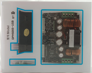
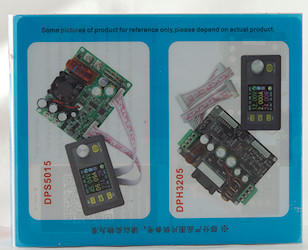
It arrived in a styrofoam box together with some other stuff, inside the box was the plastic box with the electronic.
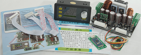
There is a control unit, a power unit, two flat cables, the usb interface, the Bluetooth interface, cable for usb/bluetooth and a manual in English and Chinese.

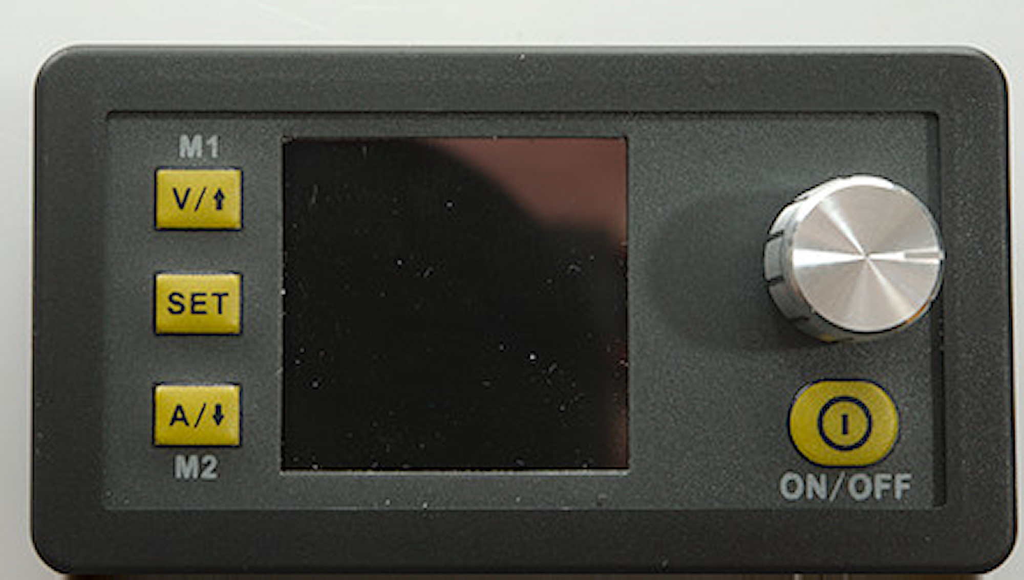
The control unit has a display, four buttons and a encoded that can be pressed.
The V and A buttons will enable adjustment of voltage and current with the encoder, press the encoder to select digit, when finished press V or A again.
Holding down V/A/SET will recall a preset, with V and A it is preset 1 and 2, with SET any of the 9 presets can be selected.
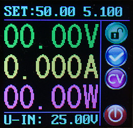
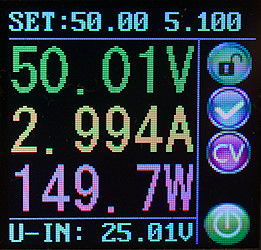
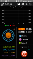
Display while off and on, set point is shown at the top of the screen and input voltage at the bottom.
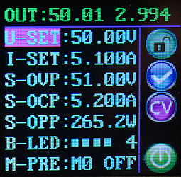
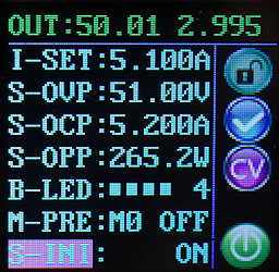
On the settings screen it is possible to define a couple of parameters: Voltage, current, over voltage, over current, over power, display brightness. The "over" settings will turn output off if they are reached.
The device has 9 preset memories. To save a preset adjust the parameters, move the marker to M0, adjust the encoded to desired preset number and hold down the SET button.
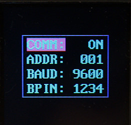
There is a hidden communication menu, hold down the "V" button while powering on the supply to activate it (Default is fine for most applications).
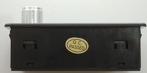
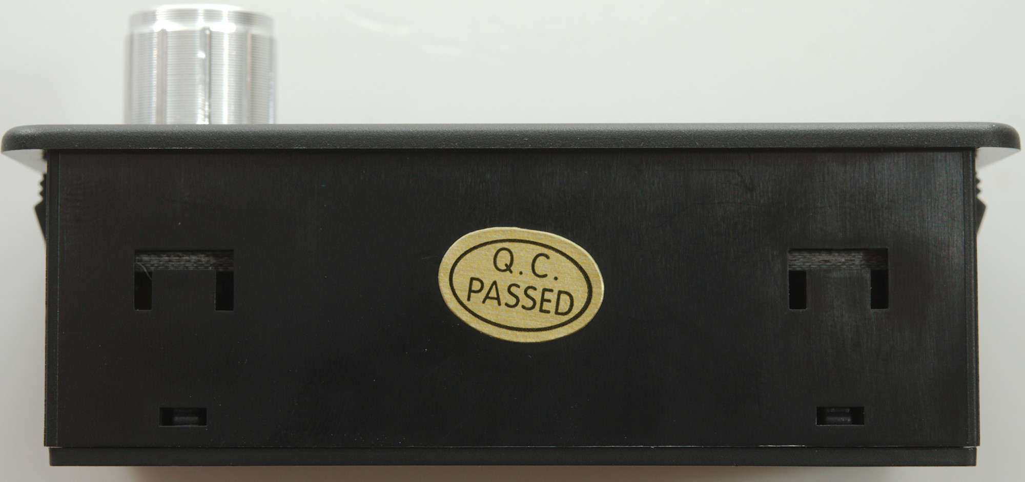
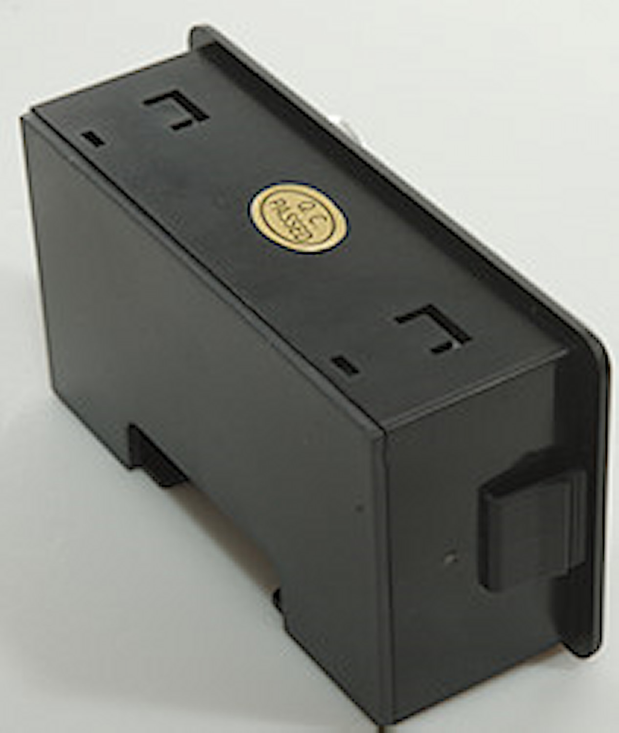
The front panel is made to be pushed into a rectangular cut-out
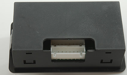
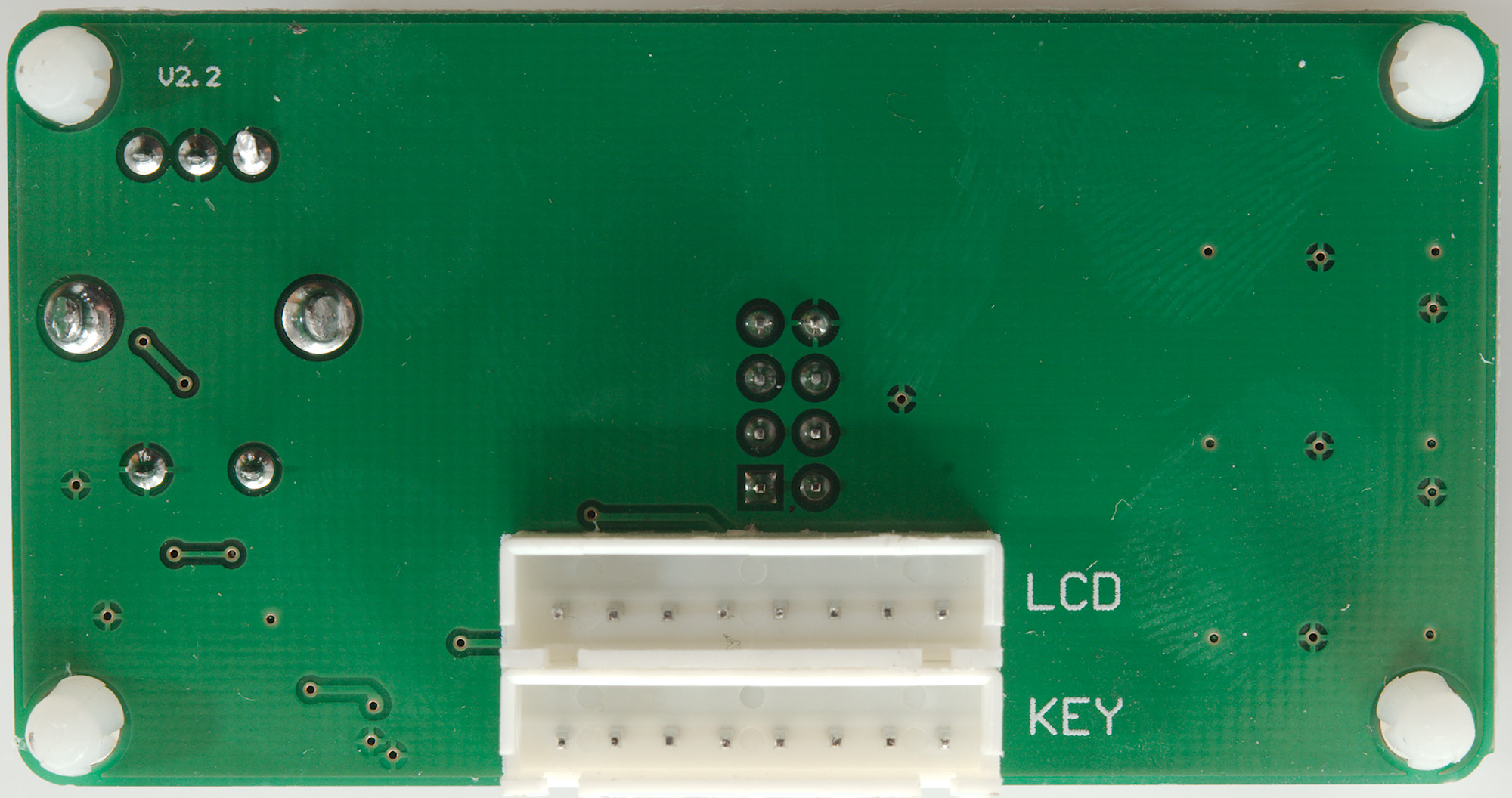
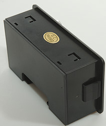
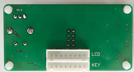
The two flat cables from the power unit is connected at the back.
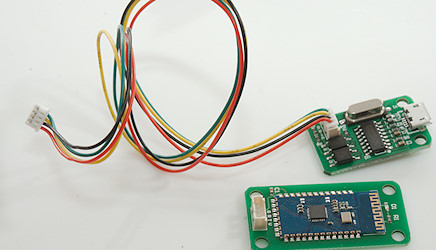
The Bluetooth and USB modules are small circuit boards and a wire to connect one of them (It is only possible to connect either Bluetooth or USB module to the power module).
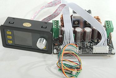
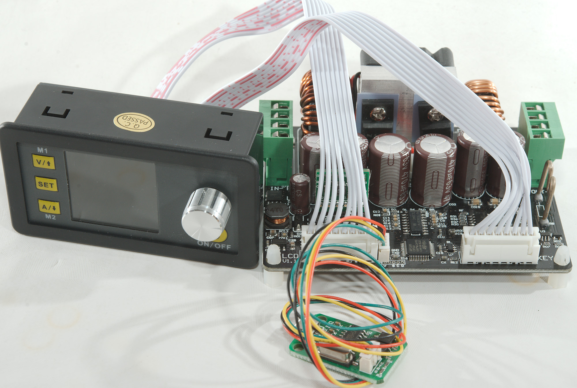
Wires connected, ready to test.
Measurements
I did a huge amount of test on this unit and will only show a few of the charts here, I have posted more in another article.
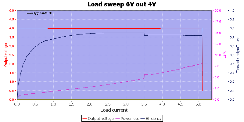
Running at low input and output voltage, the output looks stable and the fan starts at 3.5A.
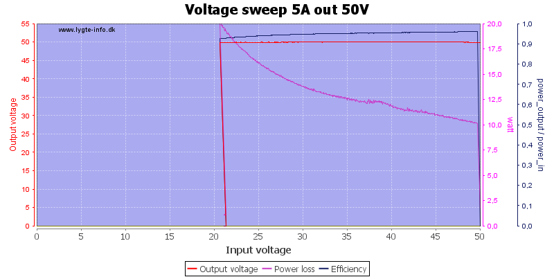
Increasing both input and output voltage, this time the fan starts earlier, probably due to a temperature sensor. The power lost in the unit is higher, but efficiency is better.

Input voltage is too low for maximum output, due to limit on input current and the supply stops at 50V 2A, this also means about 20W is wasted as heat.
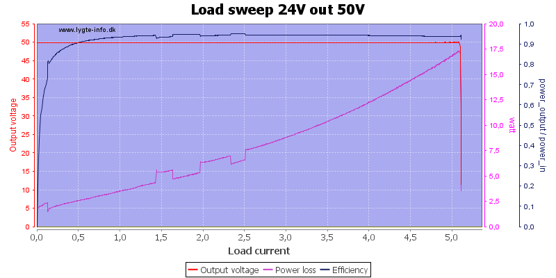
With 24V input it can maintain 50V 5A output, there is still 17.5W heat.
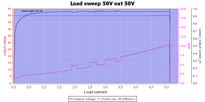
And with 50V input the heat is down to about 10W.
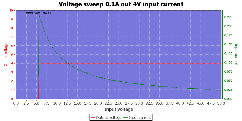
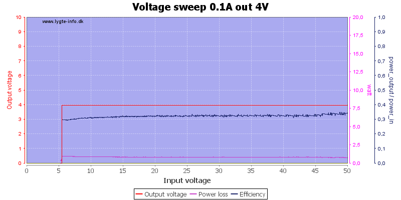
With very low output current and voltage it can maintain output voltage down to about 6V input.
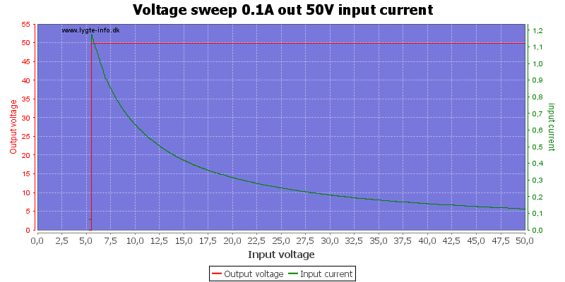
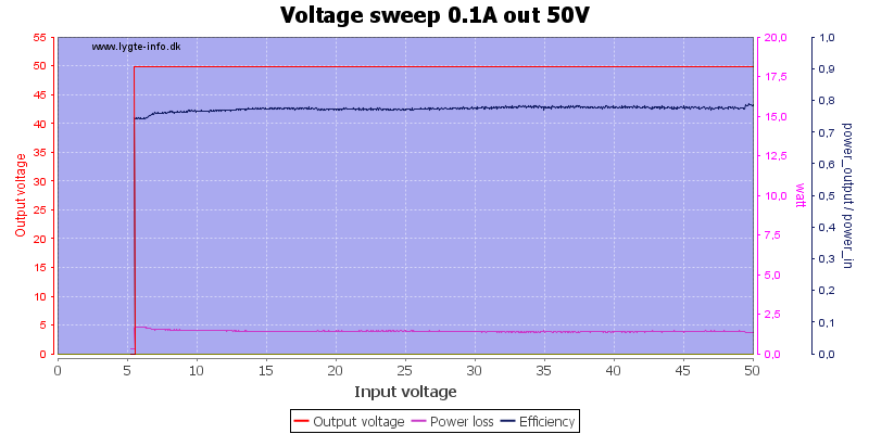
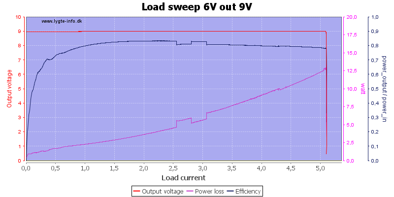
High output voltage is also possible with low input voltage.
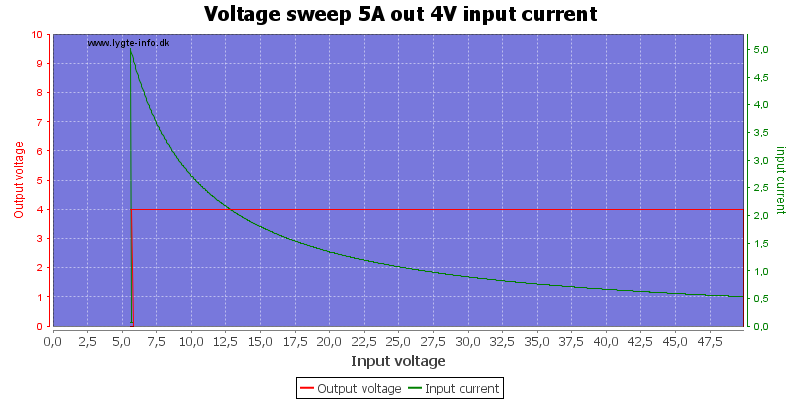
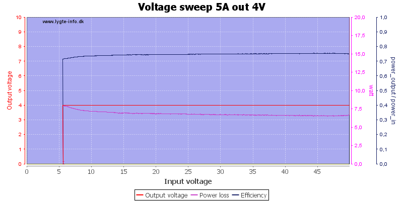
With this low output voltage it can easily maintain output at 5A with any input voltage.
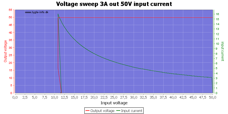
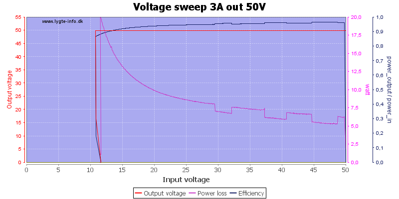
It can handle 3A output with down to about 11V input, but this is a bit outside specifications, they say maximum input current is 10A and for that 16V input is needed. Output is stable until it cuts out.
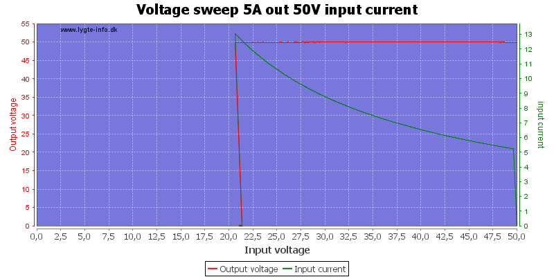
To maintain full output current at 50V it needs about 22V input.
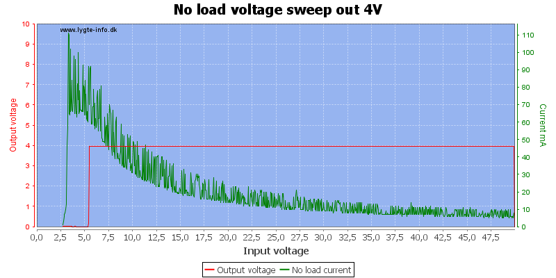
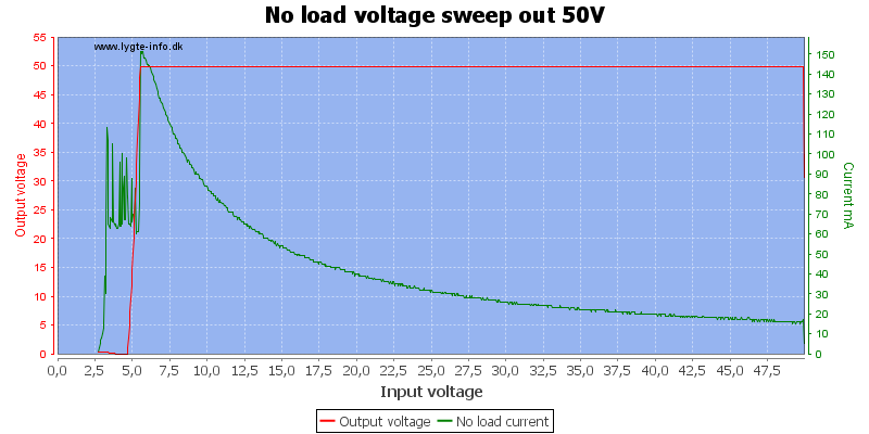
Current consumption depends on select output voltage and input voltage, but it is fairly low, even though it has to drive the display and the converts. With high output voltage it will use a bit more current to maintain the voltage.
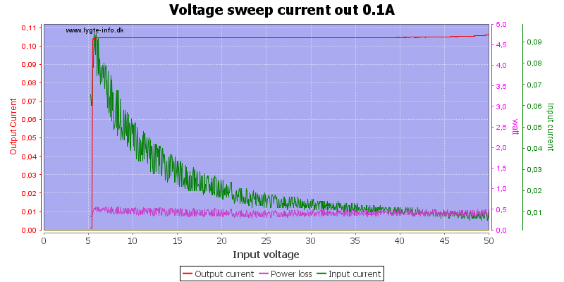
The power supply will go into constant current mode when overloaded, here I shorted the output and measured the current at 0.1A (The noise is probably due to the current resolution on my power supply).
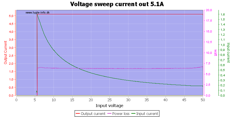
Here as a 5.1A constant current generator.
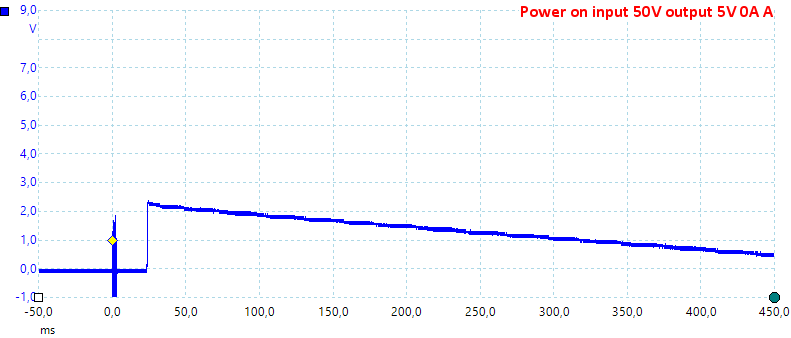
When power is connected a small transient occurs on the output.
The output turns on without any spikes.
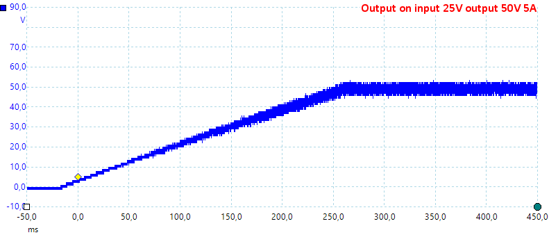
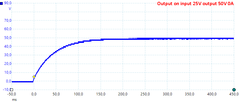
When loaded the output are slower to turn on and there will be some noise.
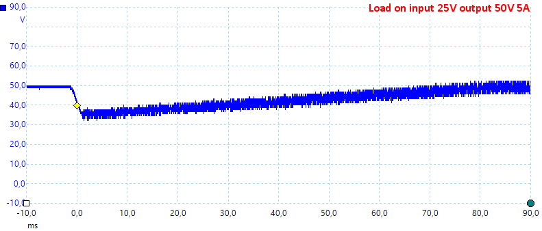
Changing the load from 0A to 5A shows a significant temporary voltage drops.
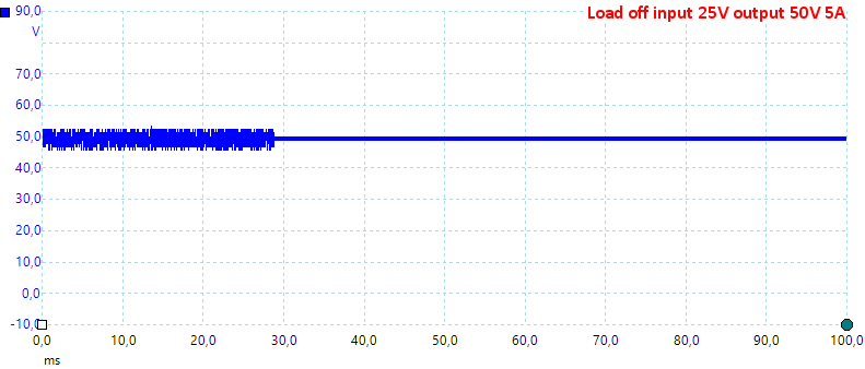
Changing the current from 5A to 0A do not show any voltage spikes.
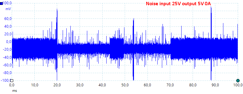
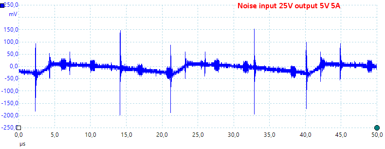
Both at low and high current there is some noise from the switcher on the output.
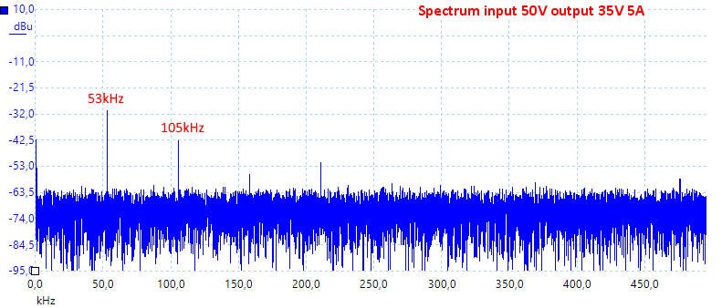
The switcher is running at about 53kHz.
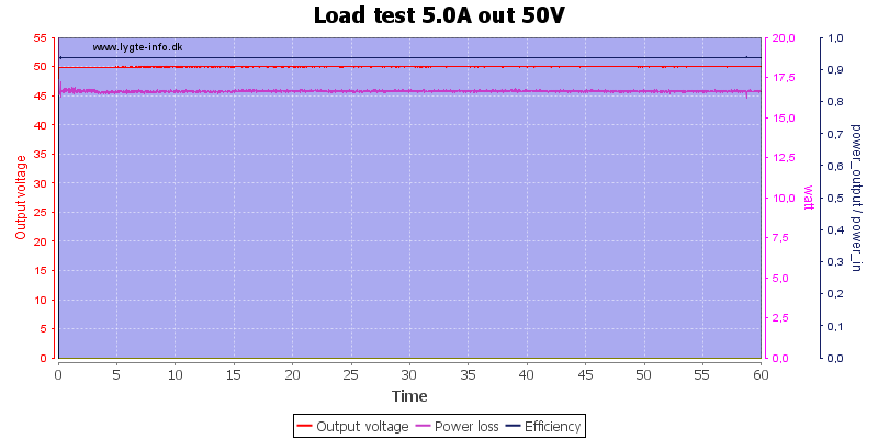
It was no problem running at full output power for one hour.
After about 45 minutes I took the temperature photos below.
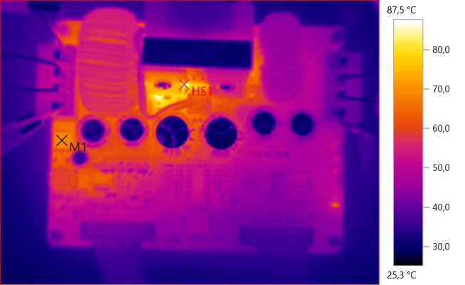
M1: 69.3°C, HS1: 87.5°C
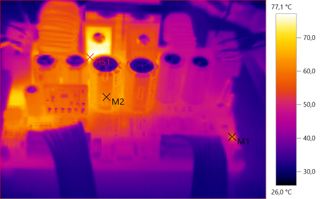
M1: 64.7°C, M2: 60.9°C, HS1: 77.1°C
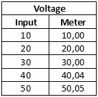
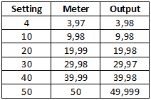
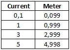
The display is precise and there is very little change with load.
Specifications says the unit can be used as a charger, lets take a look at that:
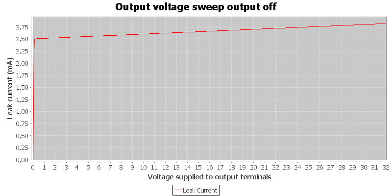
Power supply has input power, but output is off. A battery will be discharged with about 2.5mA, this is acceptable.

Power supply is supplying 5V output, if the battery voltage is higher than the selected voltage it will drain the battery, again with about 2.5mA.
The charge current is not shown in this chart, it is below the 0 line.
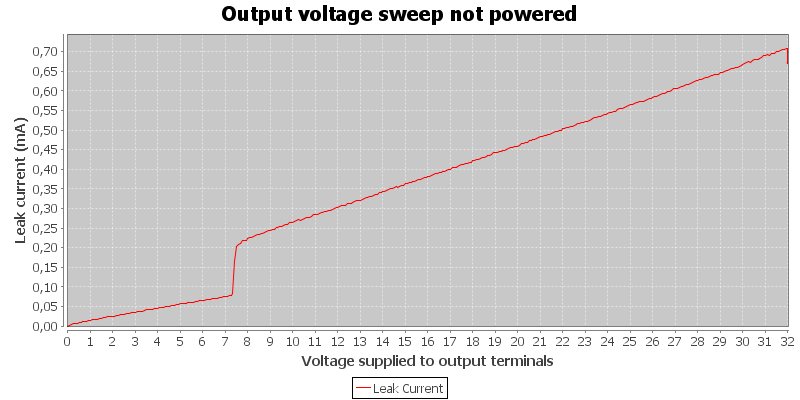
Power supply do not have input power, it will drain the battery with less than 1mA.
All in all it looks fine for charging.
Android application
- Application will show an ad for another RD product when started.
- Application is not on Google.
- RD uses a file download service that opens ads in minimized windows.
- Protocol is documented.
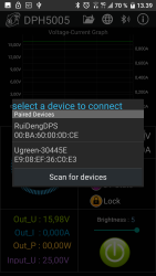
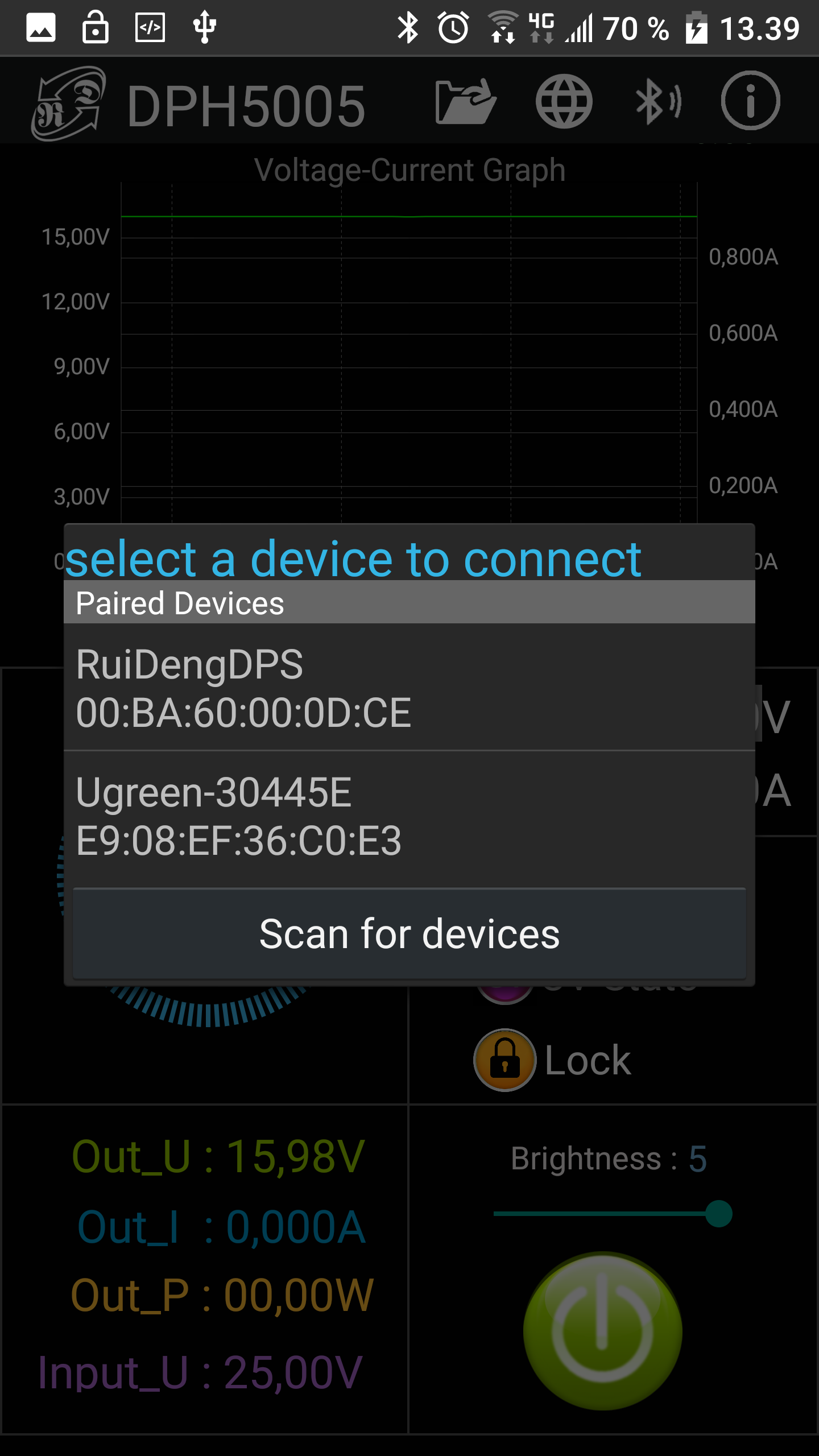
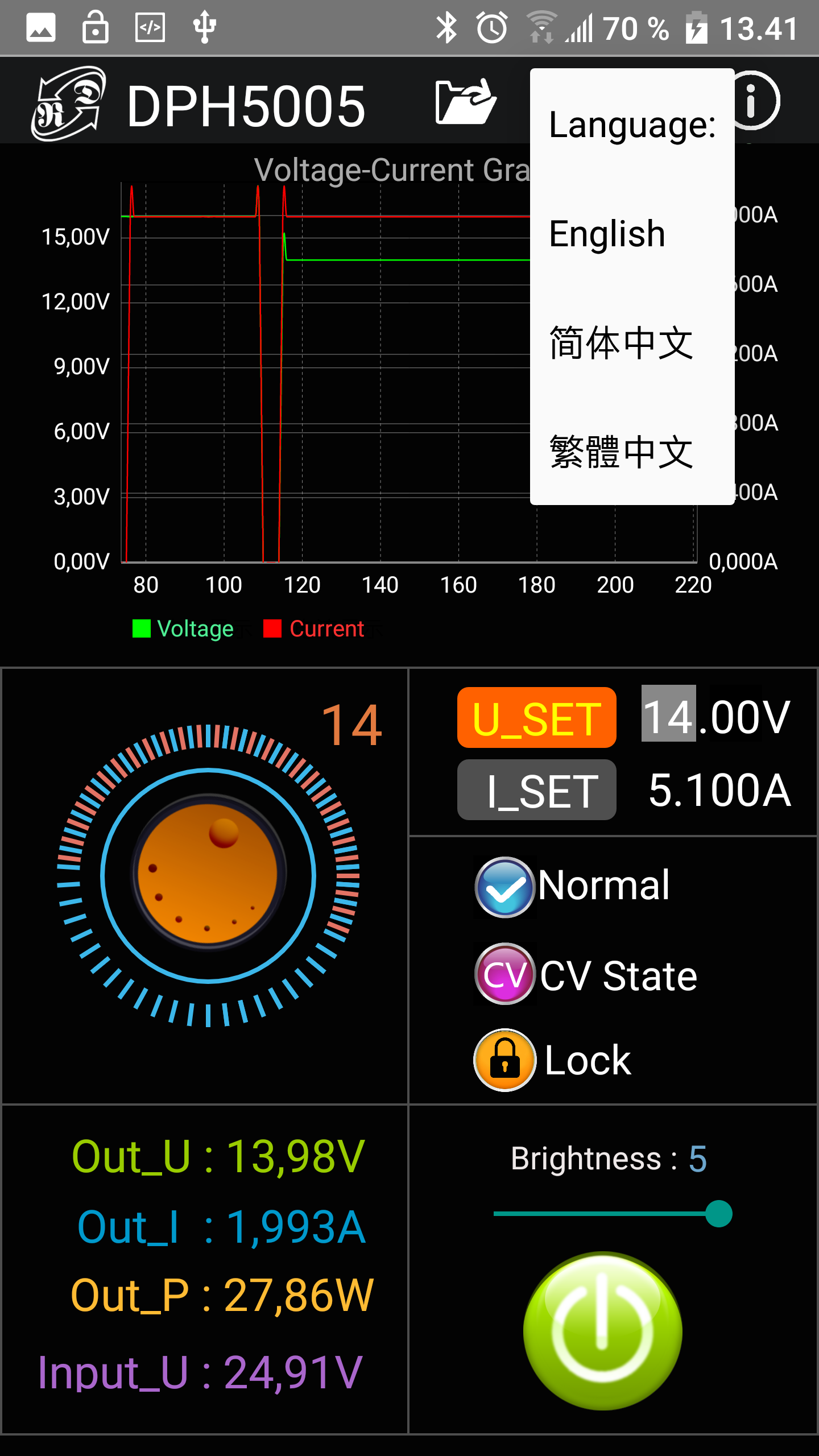
The application is basically one screen. To connect use the Bluetooth symbol, in my case I could not see the power supply and had to use the normal Android discover dialog (I did use "Scan for devices), after that it worked perfectly.
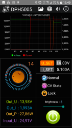
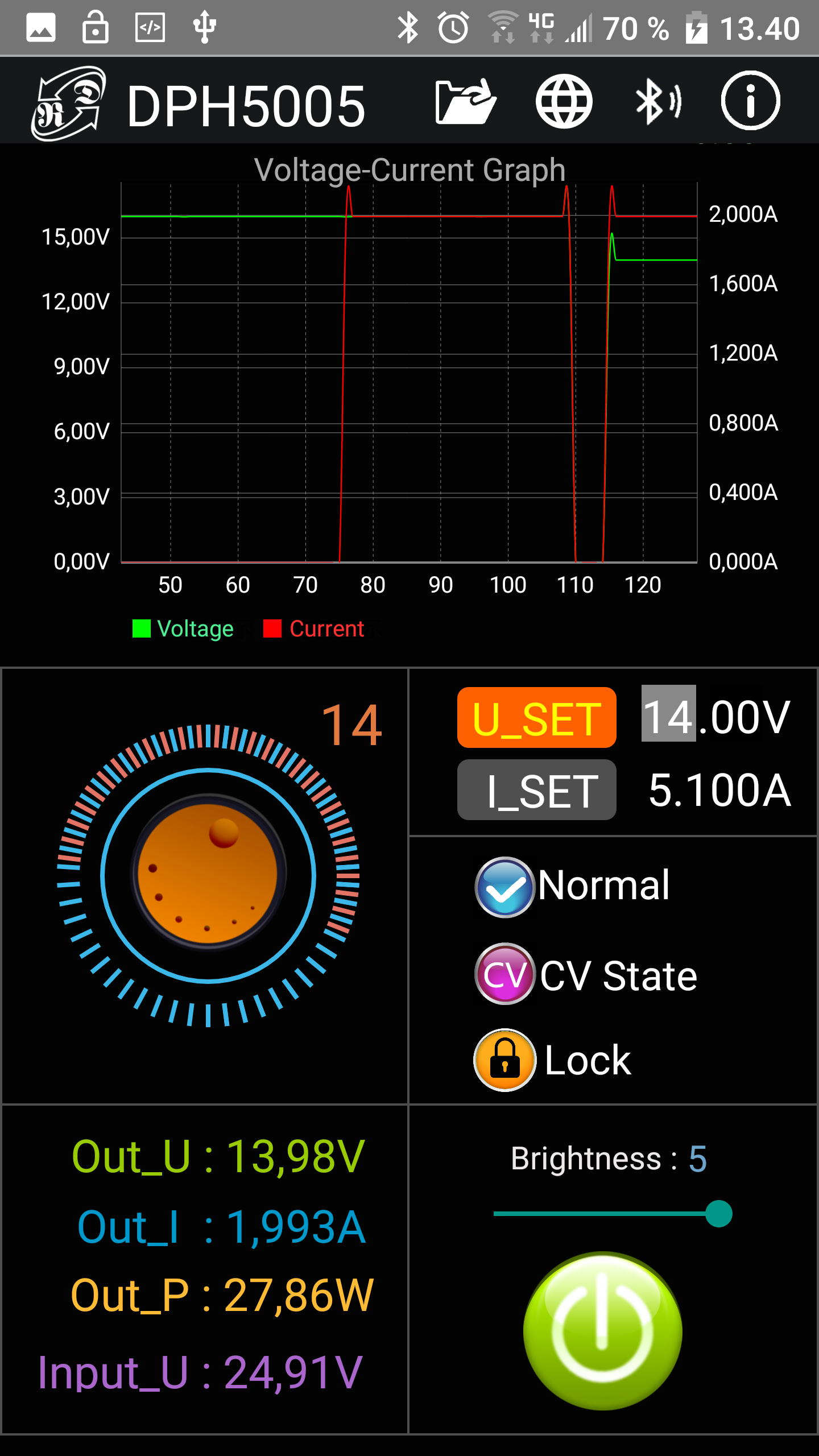
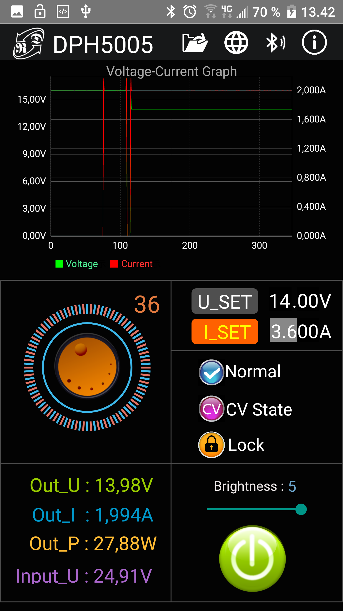
Here I am connected and can adjust voltage and current.
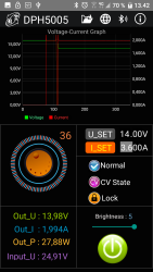
The wheel is used to adjust voltage and current with, but only two digits at a time. Touch the U_SET/I_SET and digits to select what two digits to adjust.
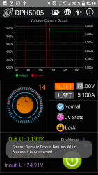
The control panel is locked while using the phone and it is not possible to unlock it. I would have preferred that at least on/off worked.
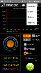
There is not many languages in the current version of the application.
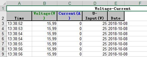
Using the file folder will save a Excel file on the phone with a fixed name, i.e. it is only possible to save one log.
PC application
- Application is a 230MB download
- Inside the archive is installation files
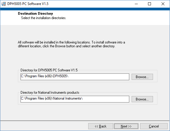
- Application is very slow to install if it has to install the National Instruments part.
- The screen is a fixed size (1062 x 619 pixels), there is no resize options.
- RD uses a file download service that opens ads in minimized windows.
- Protocol is documented.
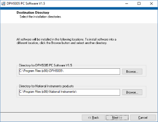
The package uses a National Instruments library, this is large and slow to install. This installation will not install the supplied font, it has to be installed manually. The letters are a bit to large without that font.
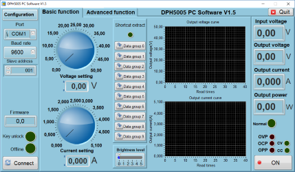
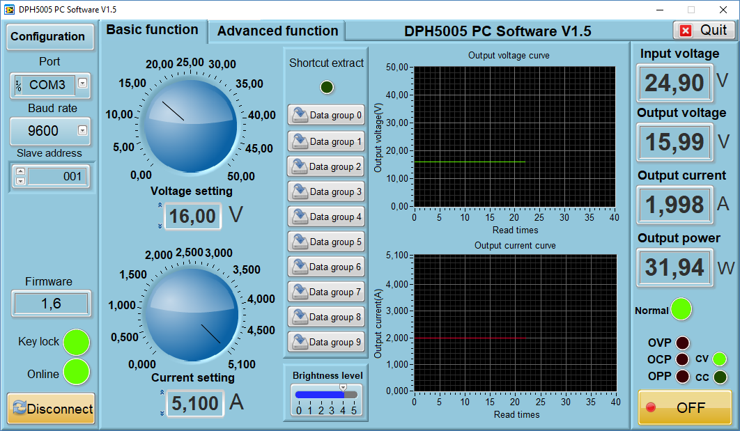
Program started, but not connected yet.
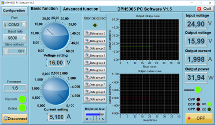
When connected the actual values and curves are added. The dials can be changed with a mouse or new values can be typed in the numeric fields.
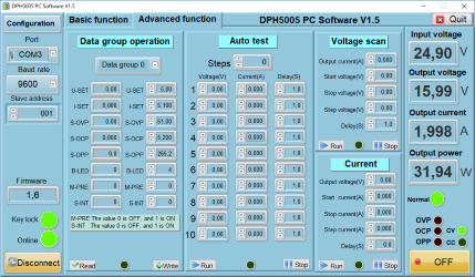
The advanced tab where the presets can be configured and 3 types of automatic sequences can be defined and used.
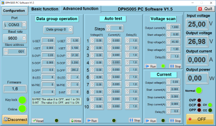
Here I have configured and started a "Voltage scan".
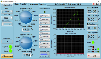
This can be viewed on the chart screen.
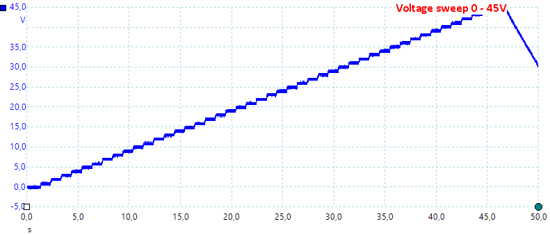
And here with a oscilloscope.
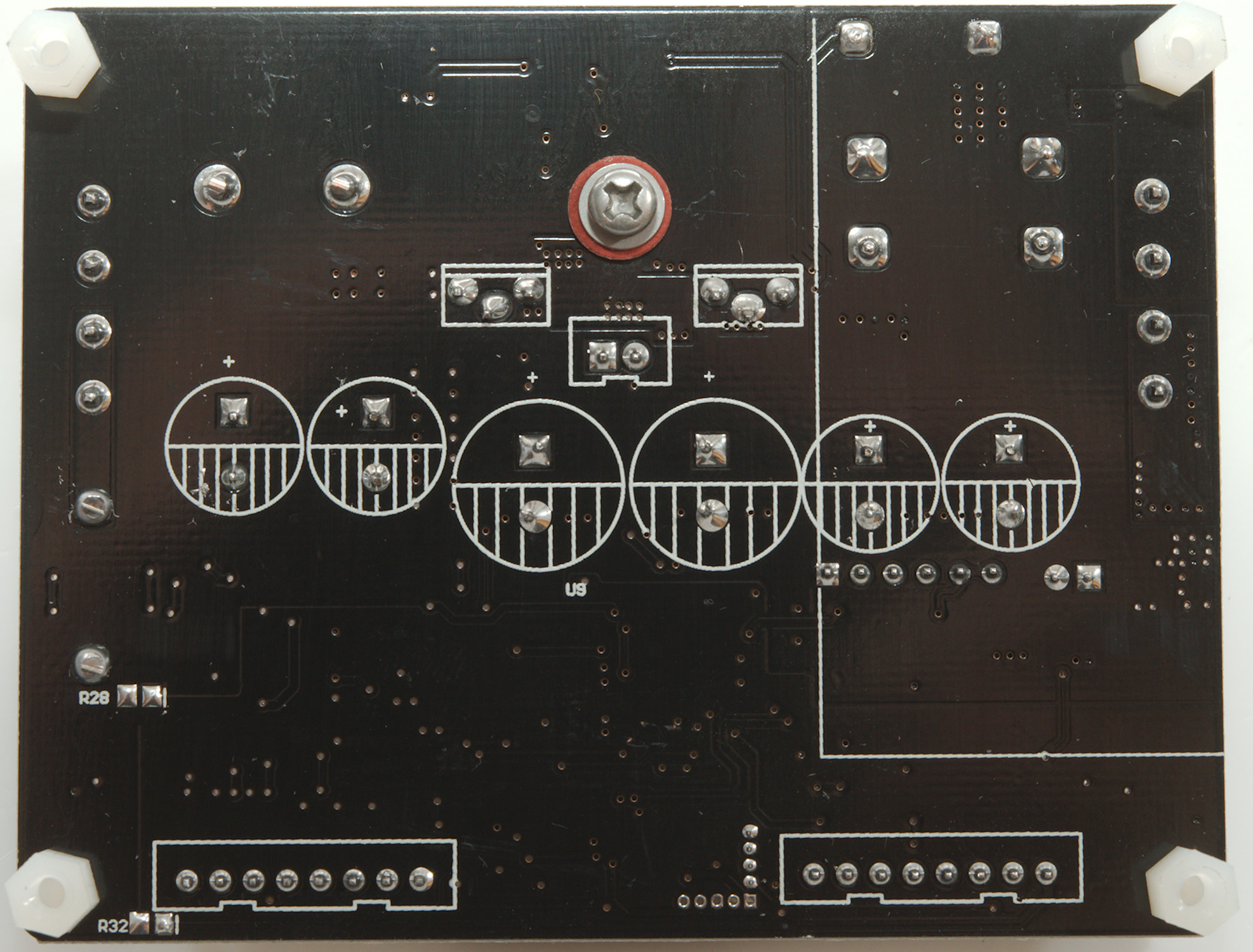
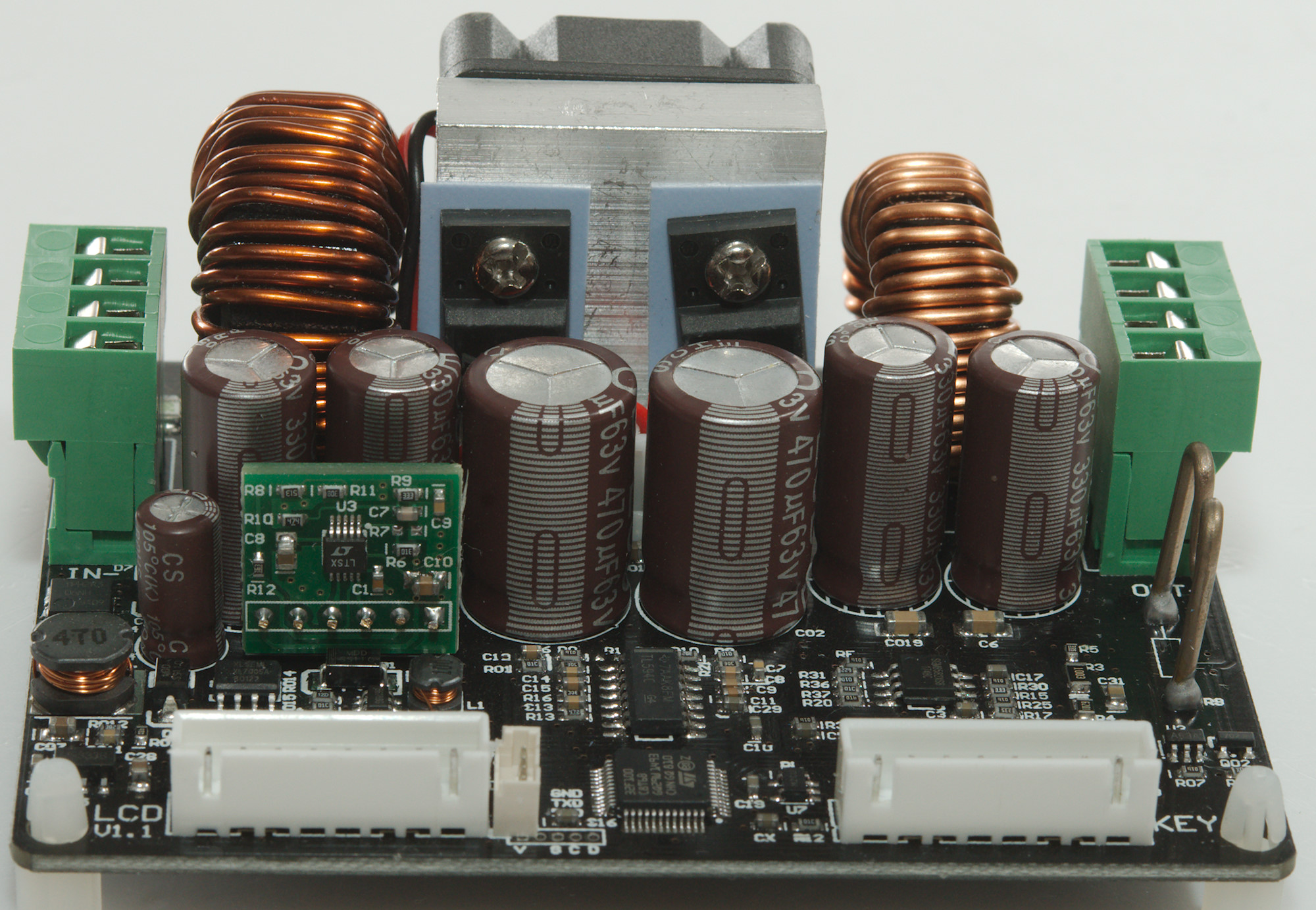
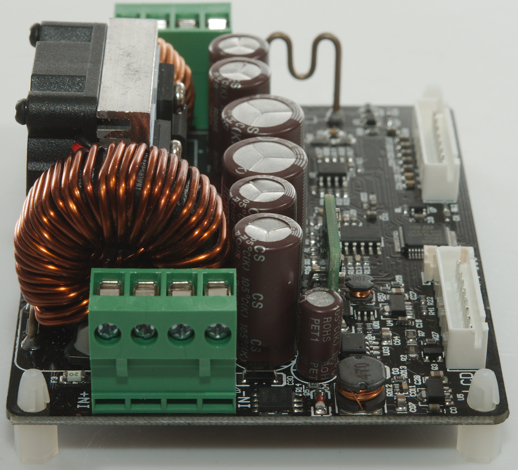
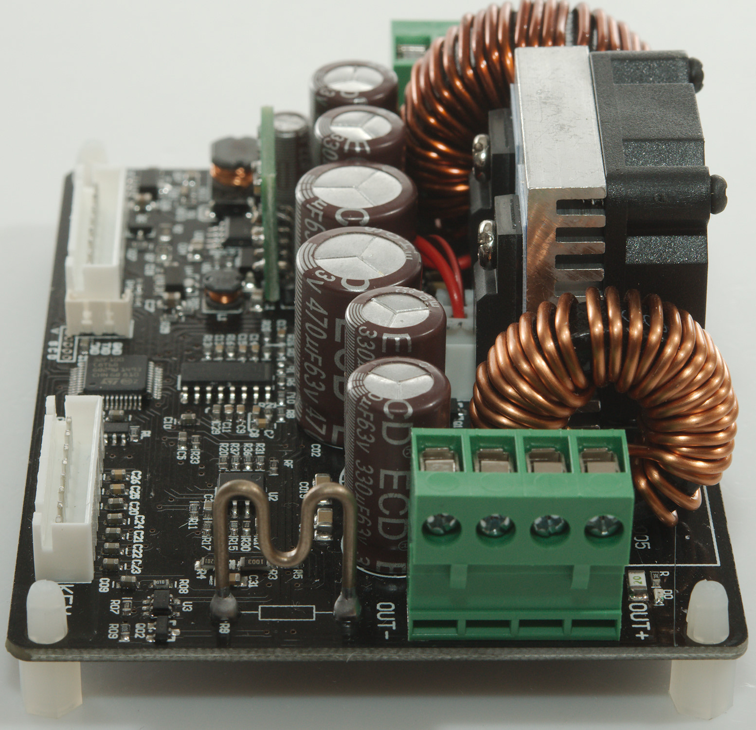
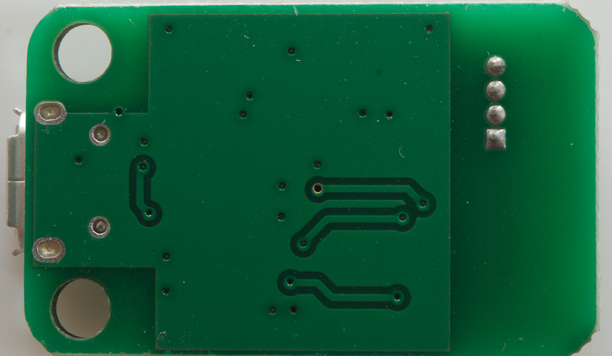
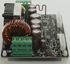
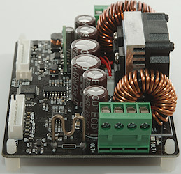
A closer look at the electronic
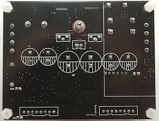
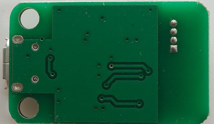
This side of the circuit board is only soldering, screws and some standoffs.
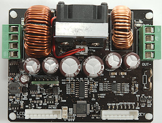
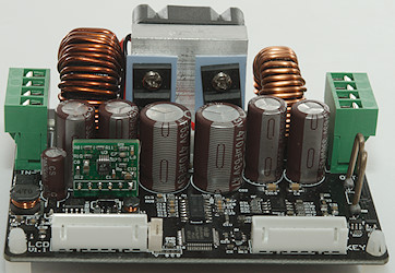
All electronic is on this side. At the input is a 20A smd fuse (F3) and a high power mosfet (Q5). The buck switcher is a TL594. The microcontroller is a 32F100. The board do also have a internal switching power supply (U03: XL7005A) and some linear regulators. The output also has a 20A fuse (F1).
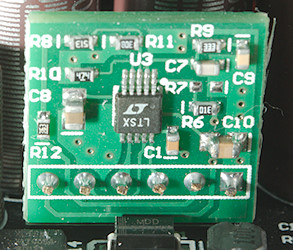
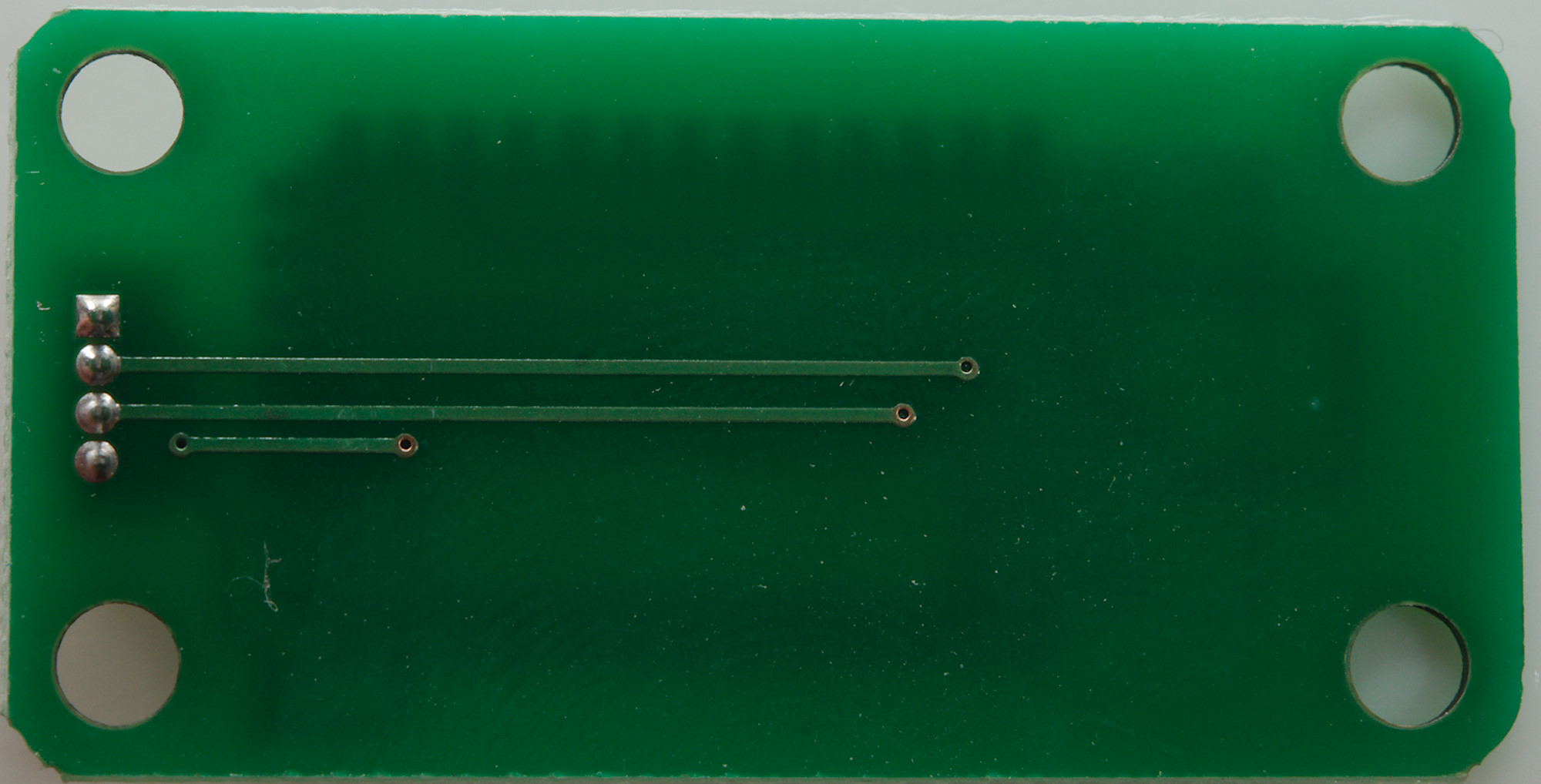
The boost regulator (U3: LTC1871) is on a small circuit board
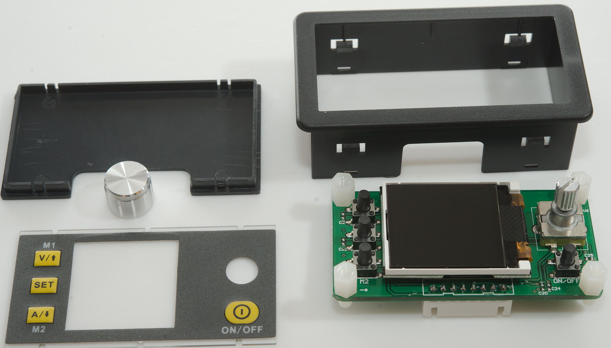
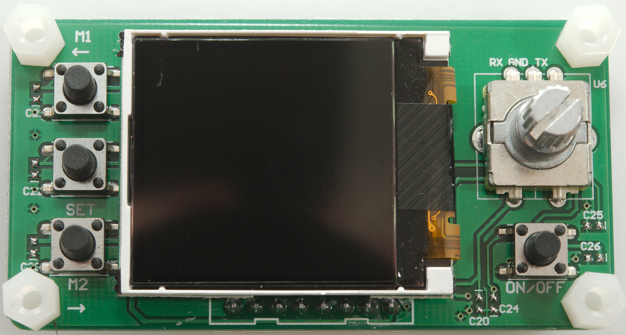
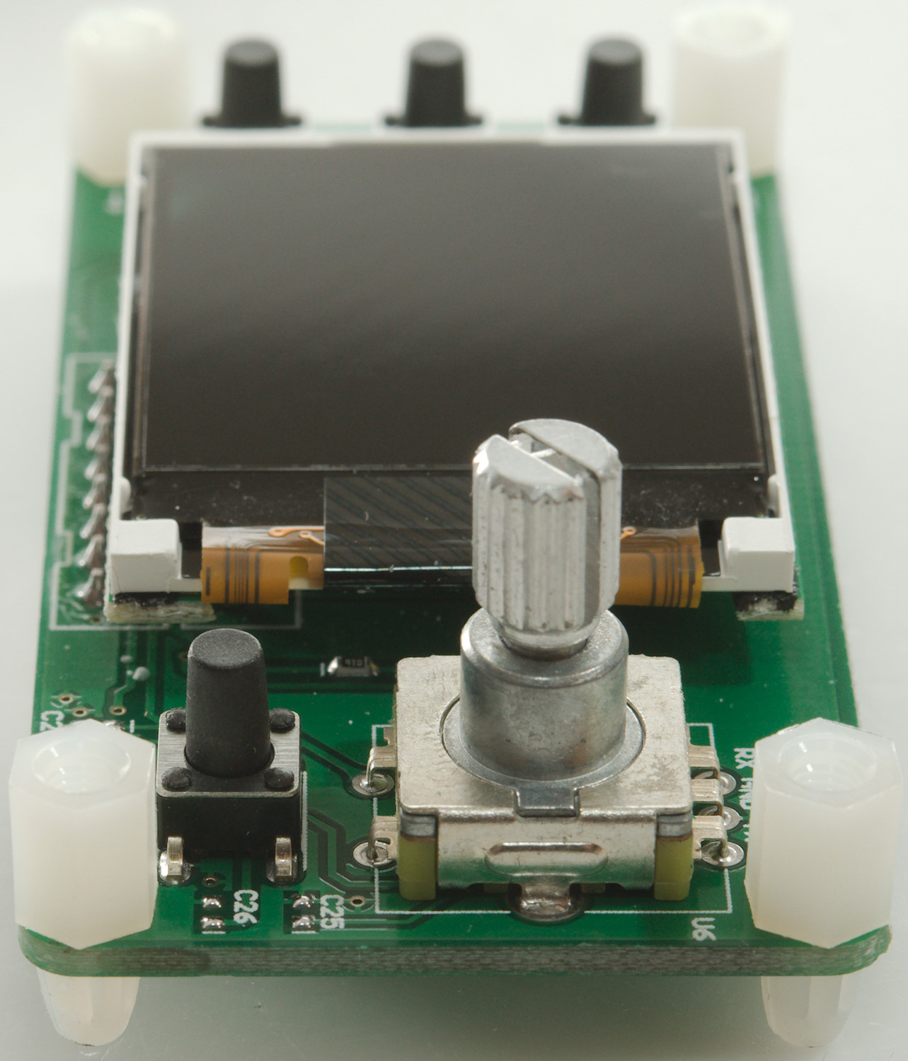
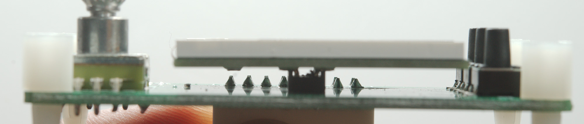
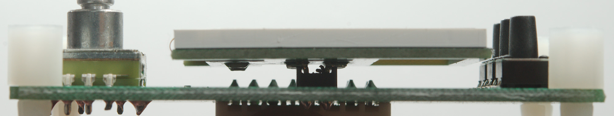
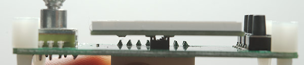
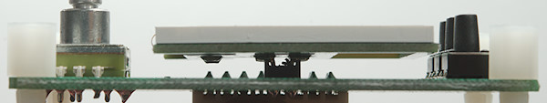
Front panel
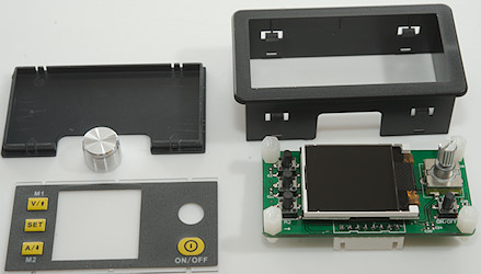
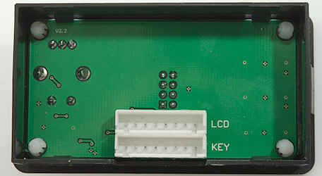
The front panel uses four clips to keep the circuit board in the box.
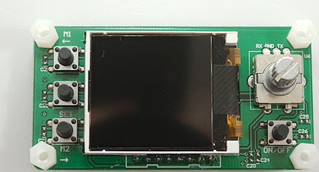
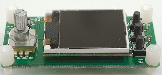
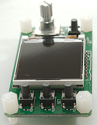
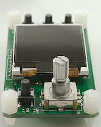
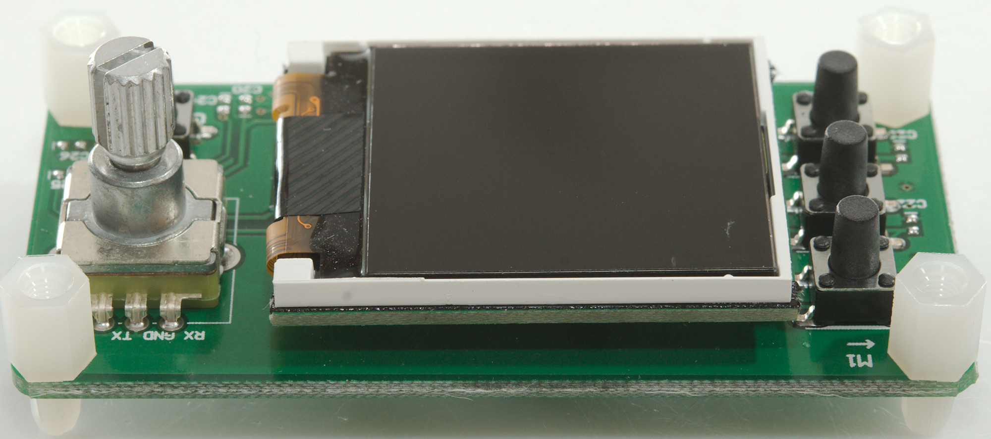
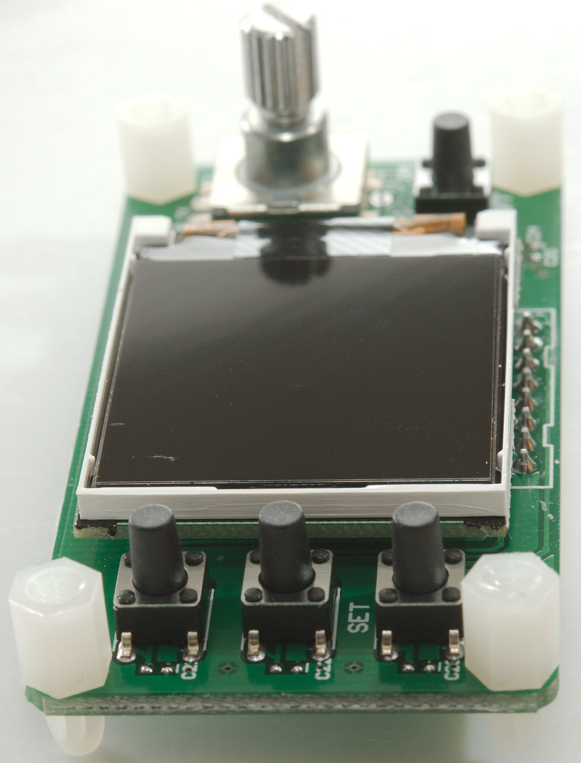
The circuit board has mechanical switches, a encoded and the display.
There is nothing hidden under the display.
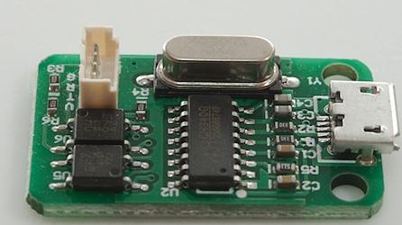
USB module
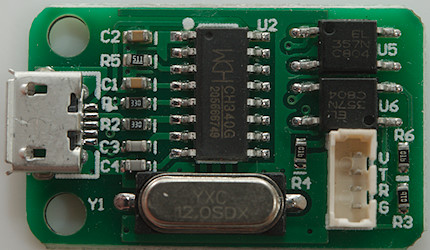
The usb module uses a CH340 chip and two optocouplers.
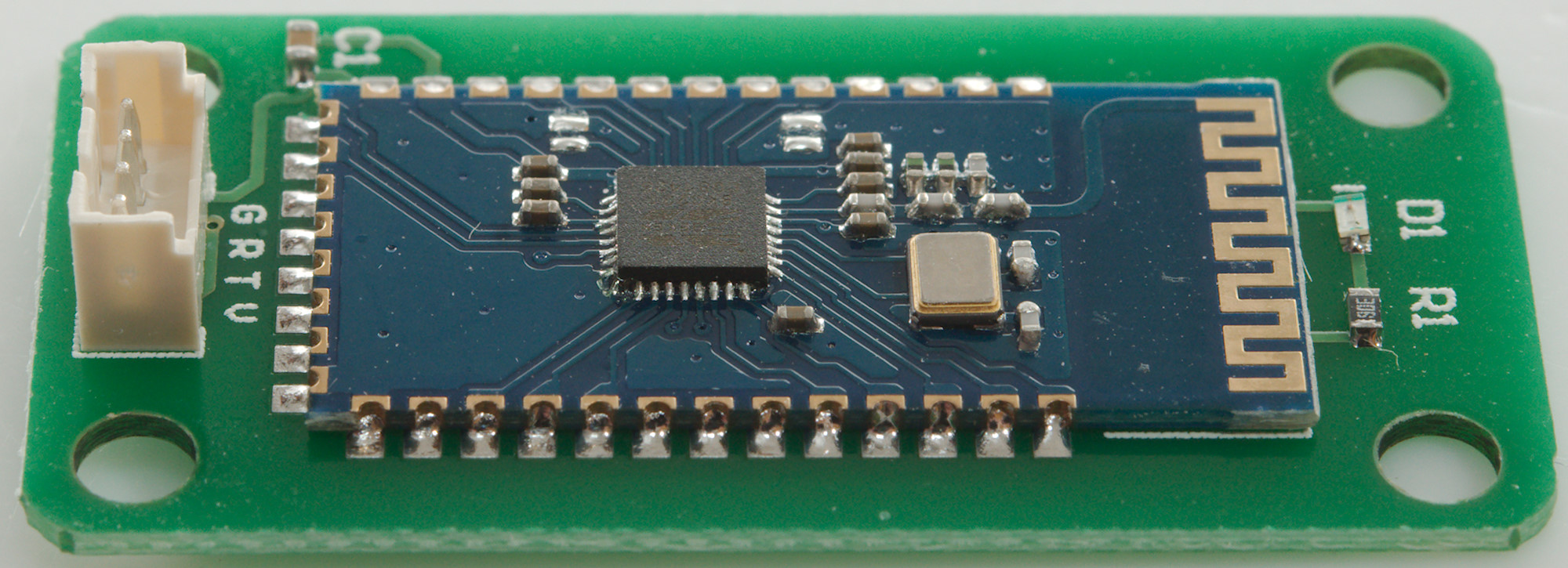
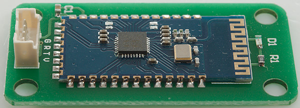
Bluetooth module
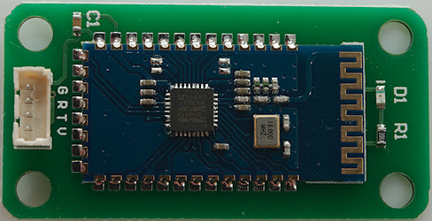
The Bluetooth module is a Bluetooth module and a led.

Conclusion
This module can deliver output voltage both below and above the input voltage, this makes is very flexible for input supply, but it need some power to deliver full output. The noise is a bit high and it has problem maintaining output voltage when load increase fast. The PC option may not be very nice looking, but it has some interesting functions on the advanced tab and I like the protocol is documented. The phone app has a very nice graphing and logging function, but adjustment of voltage and current is not that good.
This module is very useful to build a cheap bench power supply with. Add a cheap switching power supply, a box (RD sells one), some binding posts and some work.
Compared to professional units it is missing a lot: Lower noise, both numeric keypad and encoded, 4 terminal connections, larger display. But for the price it is very good and works fine.
Notes
The power supply was supplied by RD for review.
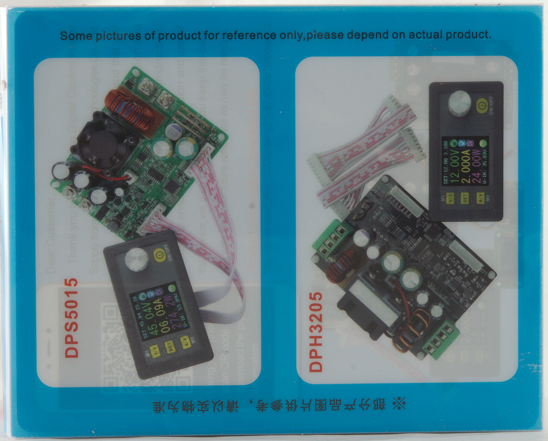
Other RD supplies I have reviewed:
Power supply frontend DPS5020-USB 50V/20A with Bluetooth and USB interface
Power supply frontend DPH3205 32V/5A with buck/boost converter
Power supply frontend DPS5015 50V/15A