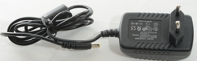
2S 1.8A LiIon charger Enerpower FY090200
Official specifications:
- Input: 100-240Vac 50/60Hz
- Output: 8.4V 1.8A DC
- Cable length about 100cm.
- Charge with CC/CV.
- Connector is 5.5mm/2.5mm
This charger is for battery packs with 2S2P (2 in series 2 in parallel) or 2S3P or more parallel LiIon cells. The battery pack is supposed to contains its own protection and balancing.

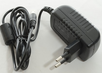
I got the charger in a simple cardboard box.
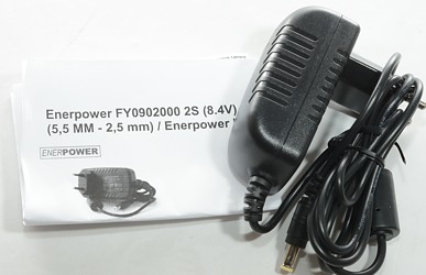
A manual was included.
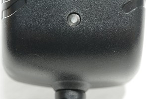
The led shows red when battery pack is full, green at all other times when the charger is connected to power.
A short will make it flash red.
Measurements
- Connector is 5.5mm/2.1mm
- Idle power consumption is 0.22 watt
- Has short circuit protection, red led flashes and current pulses.
- Unloaded voltage is 8.45 volt
- Will start charging at 3.1 volt.
- The charger will discharge a battery with 7mA when not powered.
- Green led is on when connected to mains or a battery.
- Red led is on when connected to mains and a full battery.
- When not connected to power it will discharge the battery with 7mA
Testing with 4 cells means a 2S2P pack.
.png)
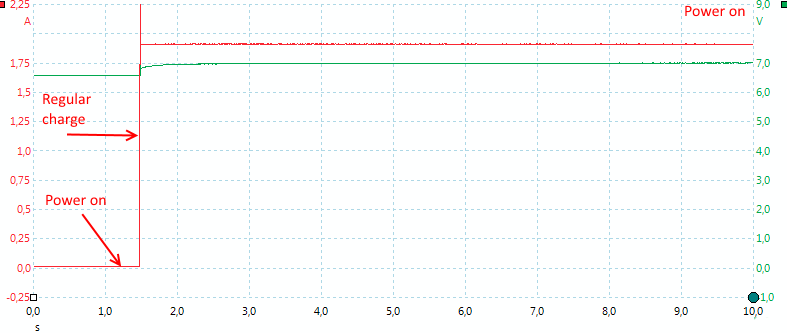
The charge curve is a CC/CV, but the charger never stops, it just reports battery full (Green led) and continues to charge (The voltage will be limited to a safe level).
%20Efficiency.png)
Same curve as above, I have just replaced capacity with efficiency, it is at about 80% during charge.
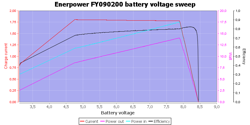
In the above curve I simulated a battery voltage from over discharge to fully charged. With serious over discharged batteries the charger will start with a low current, during normal charge the current is constant.
During a charge I took IR photos at regular intervals of the hottest part of the charger:
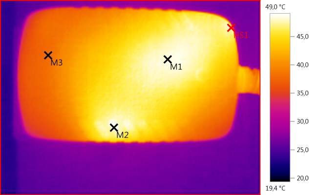
M1: 48,4°C, M2: 48,7°C, M3: 38,1°C, HS1: 49,0°C
Nothing is getting really warm. M1 is the transformer.
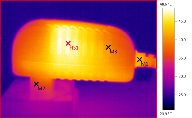
M1: 42,0°C, M2: 34,6°C, M3: 40,8°C, HS1: 48,6°C
HS1 is the switcher transistor with its heatsink.
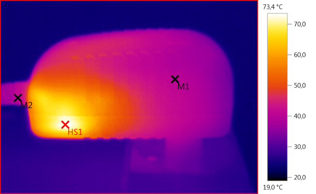
M1: 40,0°C, M2: 41,8°C, HS1: 73,4°C
But there is one part in the charger that gets hot, this is the rectifier diodes.
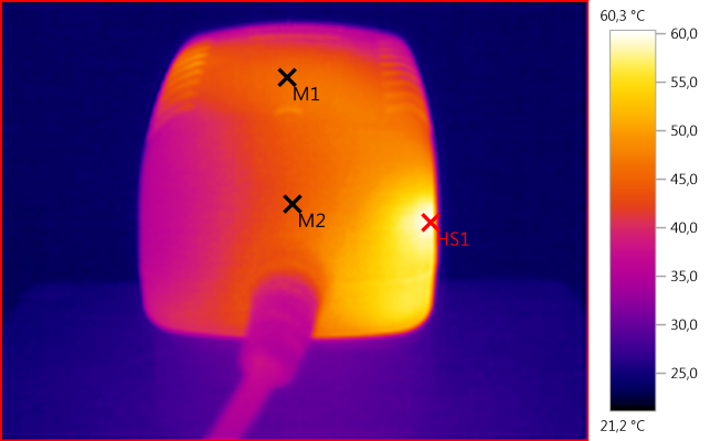
M1: 45,9°C, M2: 44,1°C, HS1: 60,3°C
The charger starts fast and charges with a steady current.
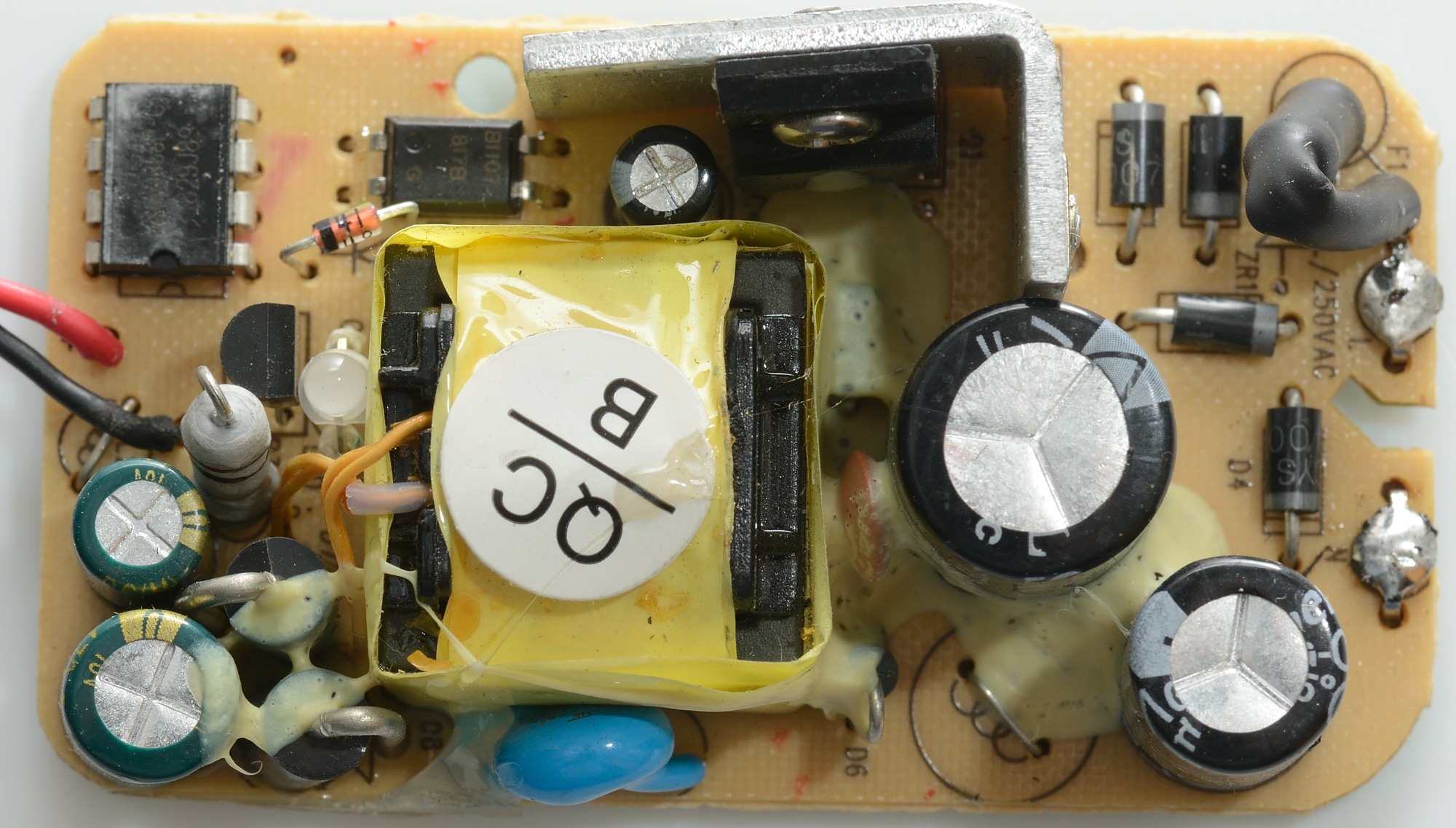
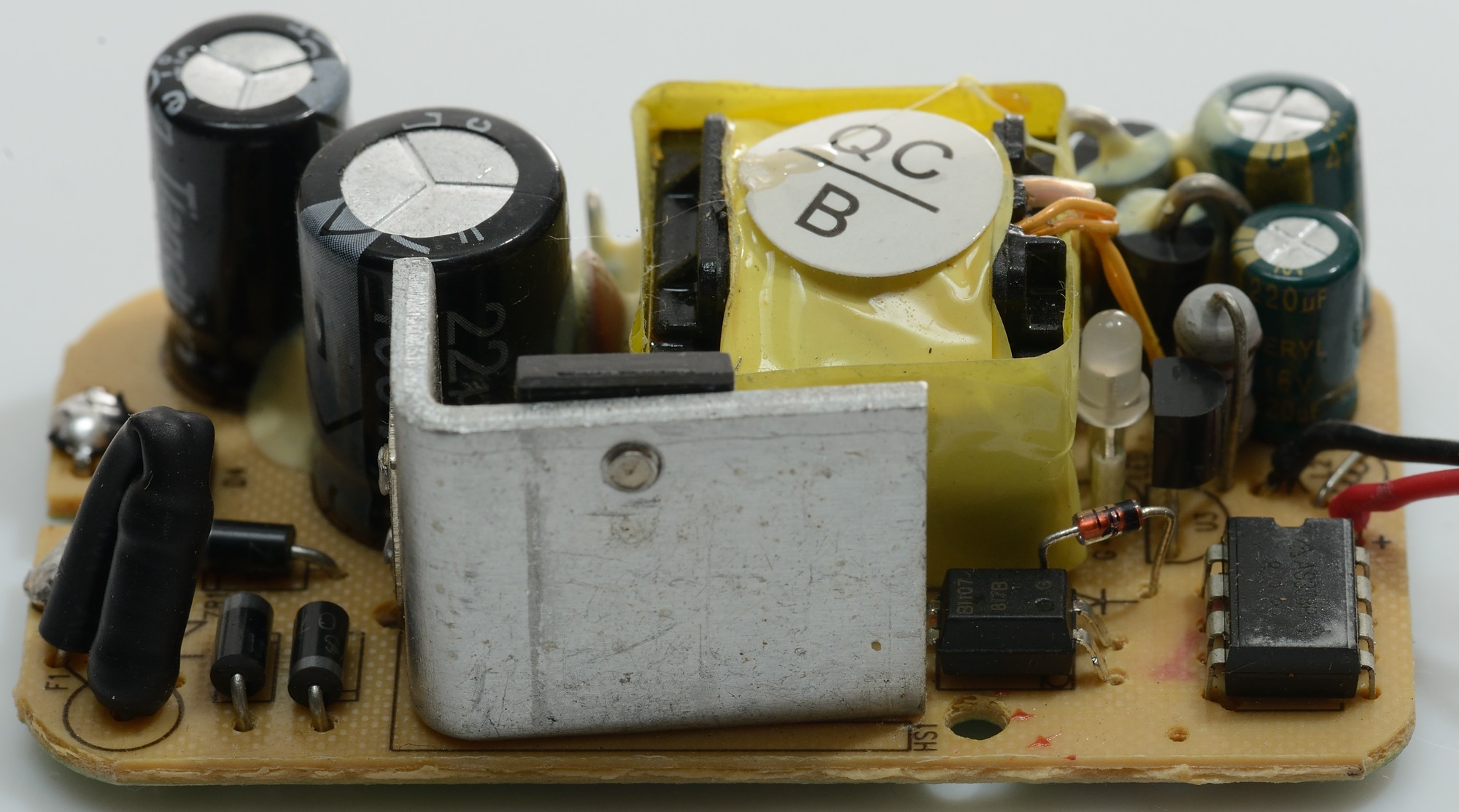
Tear down
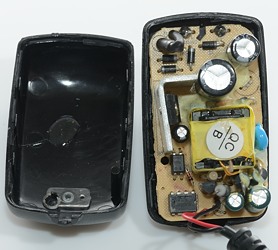

As usual the charger could be opened by putting some pressure on it. The mains connection is not made by the often seen wires, but instead by a safer fixed connection.

On the input side there is a fuse and a bridge rectifier (4 diodes) followed by a capacitor. There is space for an inductor on the circuit board, but it has been replaced with a resistor.
On the output side there are two diodes, a current controller IC and the optical feedback.
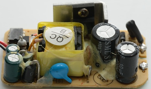
Here the safety capacitor and one of the output diodes can be seen.


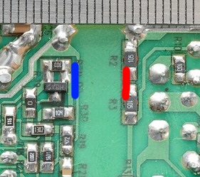
The fat resistor close to the current controller IC is the current measurement resistor.
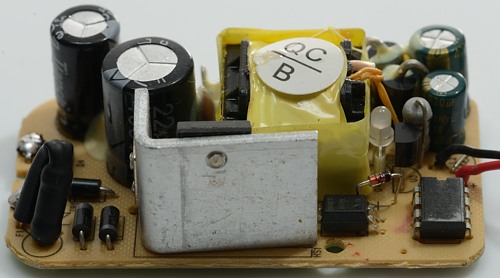
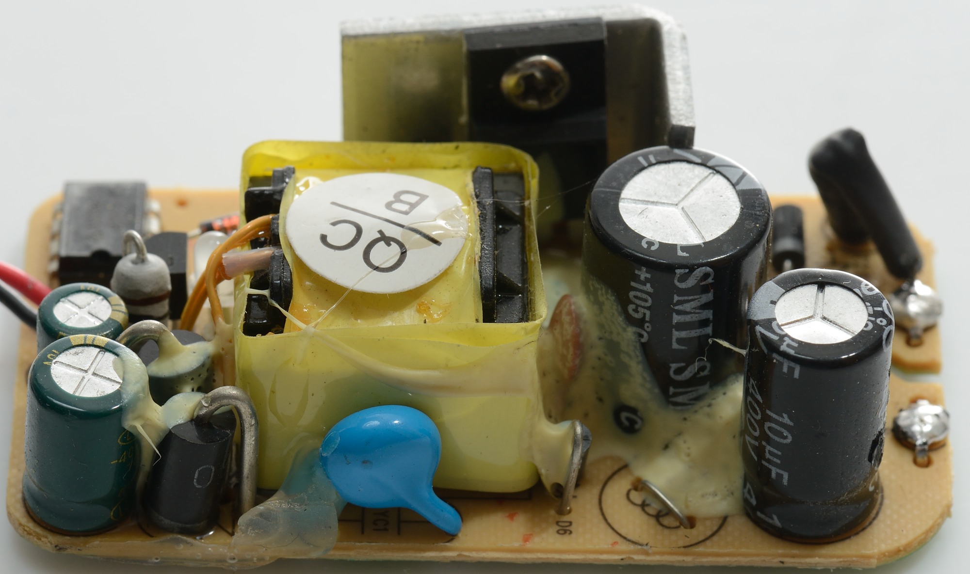
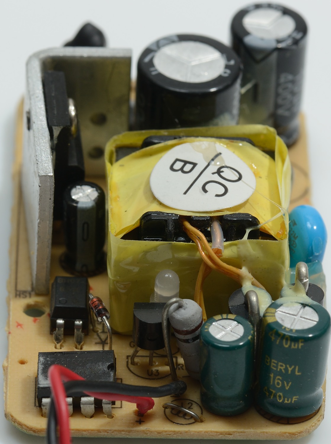
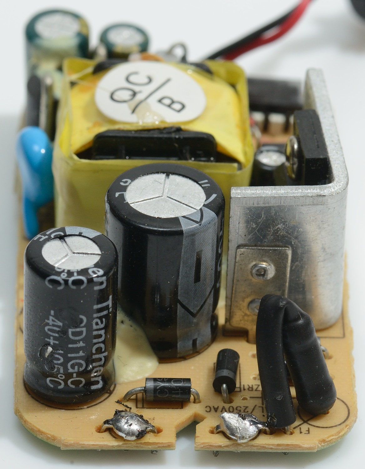
The mains switcher transistor with its heatsink is very visible here. Also notice that the low volt wires from the transformer comes out on top. This is sometimes done to improve isolation.
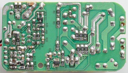
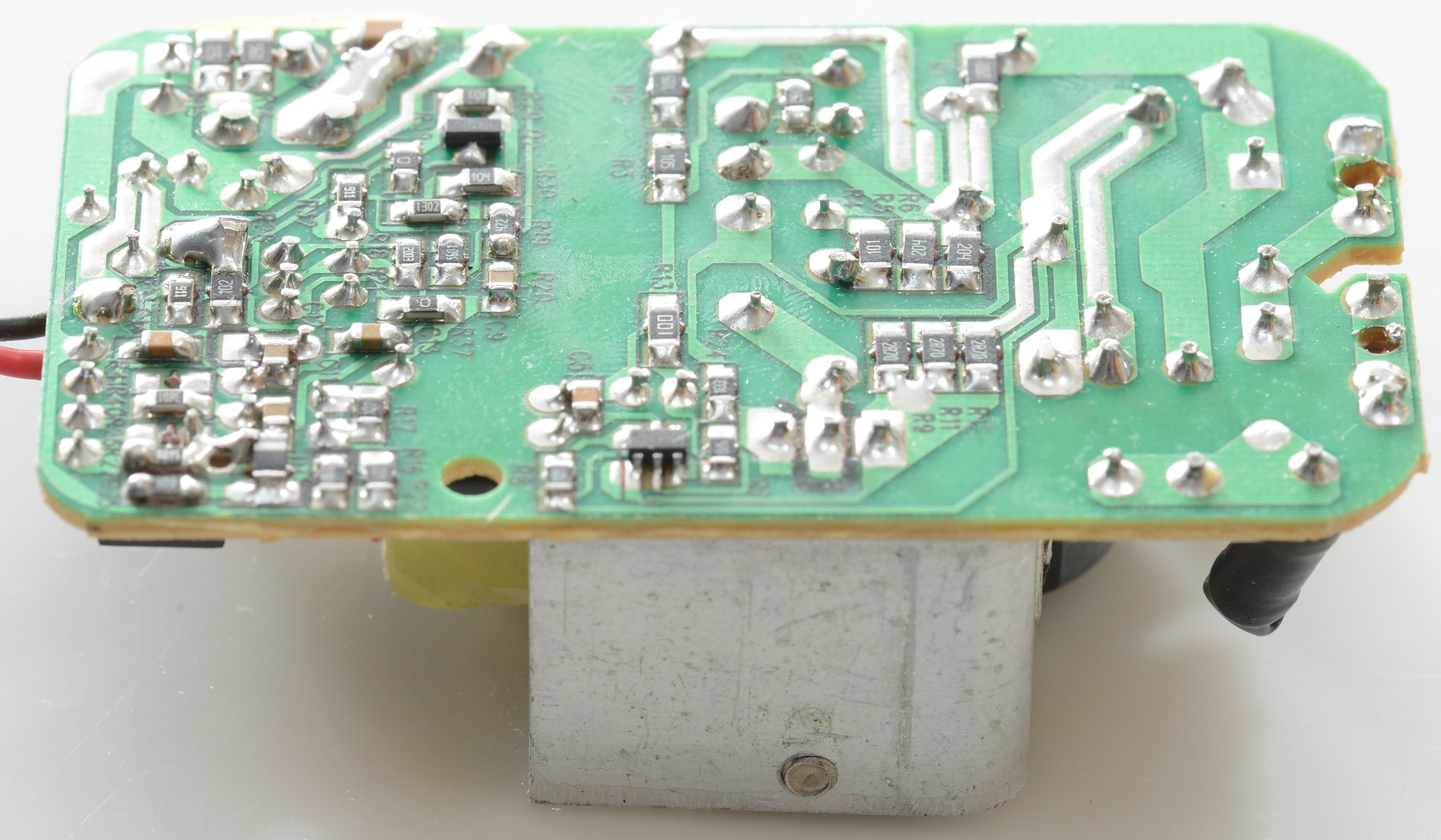
There is a lot of parts on the back, including the mains switcher IC. Notice R9, R11 and R12 (Each 2.7ohm), they are in parallel and there is traces to the mains switch IC from both sides, they are probably used for current limiting.
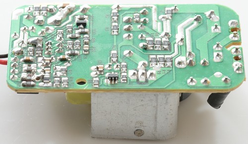
There is 6 mm space between high volt side and low volt side on the circuit board.
Testing with 2500 volt and 5000 volt between mains and low volt side, did not show any safety problems.
Conclusion
This type of charger is not nearly as advanced as single cell chargers. With only two wires to the battery pack it is impossible to do any balancing.
The charger has a few issues: It will slowly discharge the battery without mains connected (Will drain the battery in a few weeks) and it never turns the charge current off.
I will give this charger an acceptable rating.
Notes
The charger was supplied from Enerpower for review.
According to Enerpower they got a small batch with the wrong connector.
Here is an explanation on how I did the above charge curves: How do I test a charger