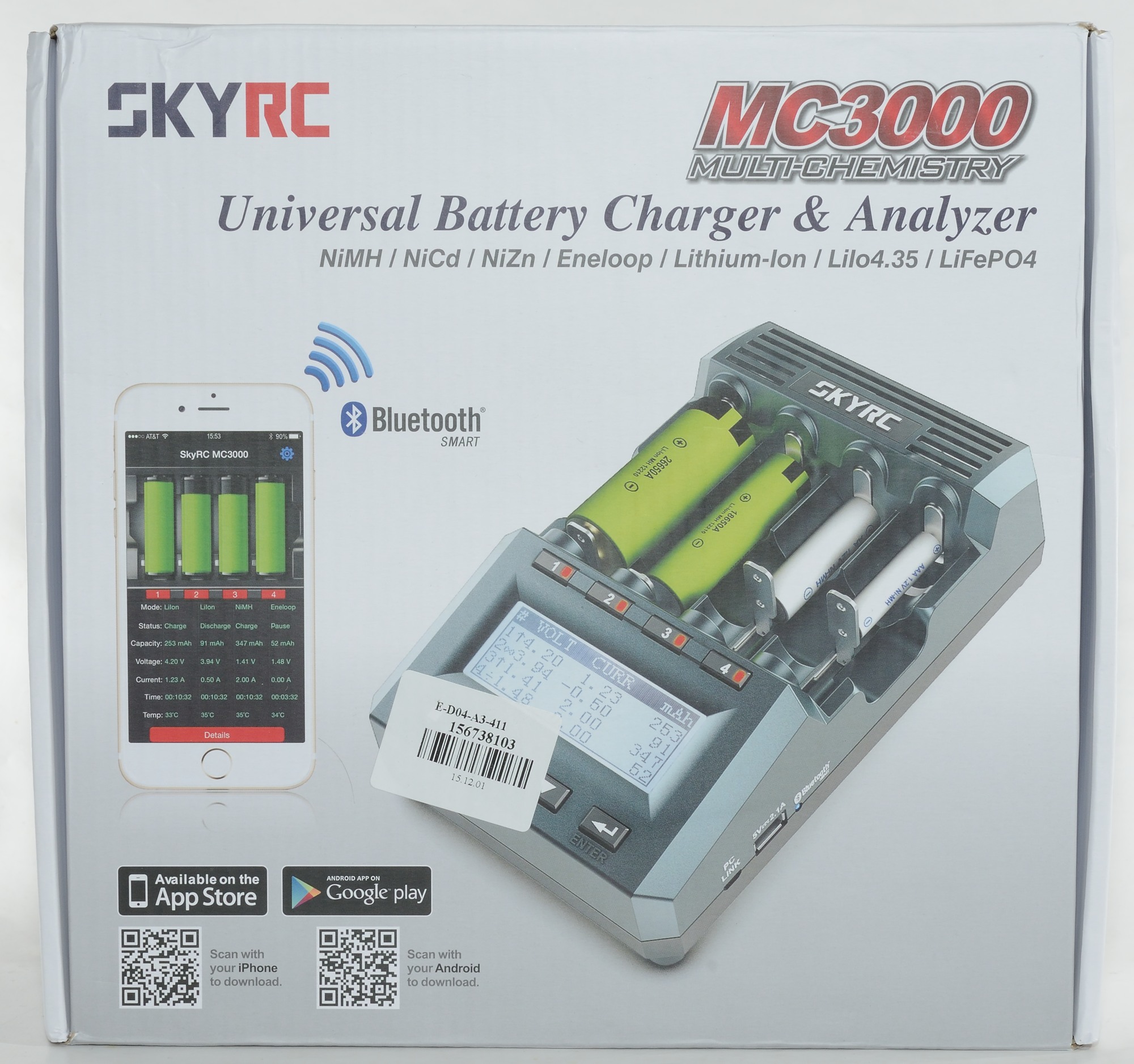
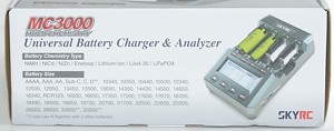
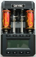
Charger SkyRC MC3000
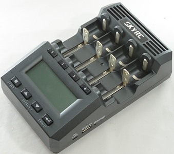
SkyRC makes advanced charger and some other equipment. This charger is a very advanced charger for cylindric cells of just about any type. This charger is more advanced than the usual hobby charger, but it is designed to handle four cells independently and not battery packs.
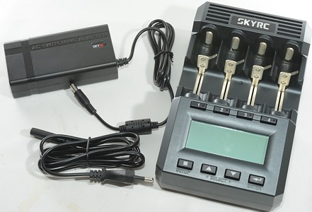
I got the charger with a power supply and a mains cable. Because I got the charger before the manual and box was finished I did not get that.


I did very soon realise that it was a good charger and that I could use some of them, therefor I put in a order and this order arrived a few days before I was going to publish the review. This has made it possible to add the above pictures of the box and do a few tests on the regular production units.
The contents of the box were the same as above, but with the manual included.
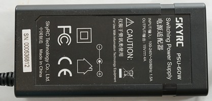
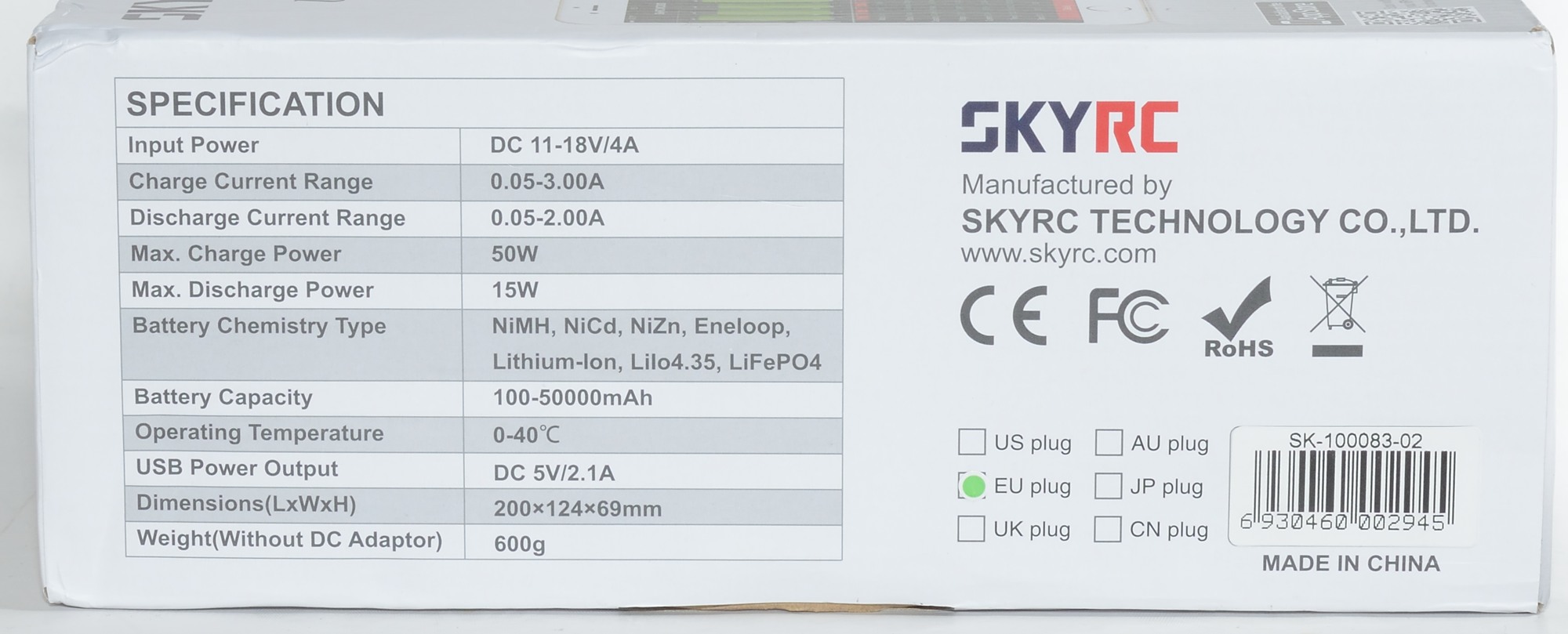
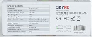
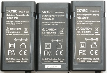
The power supply is a 15V 4A brick and the actual mains connection is handled by the supplied power cable. This makes it possible to use the same power supply for all countries.
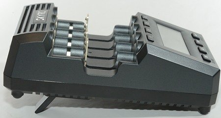
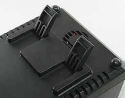
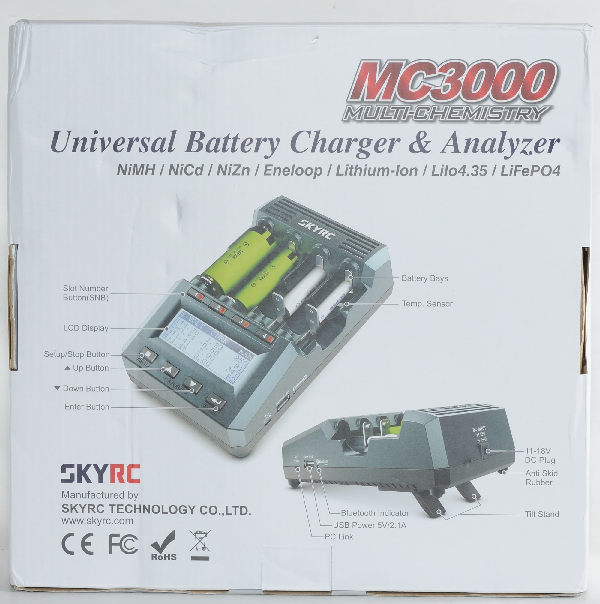
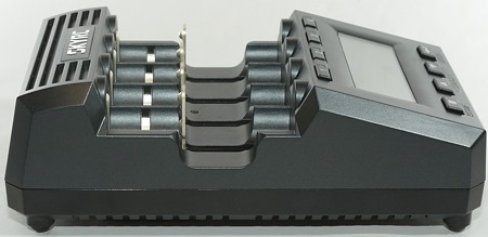
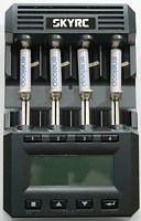
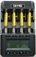
The charger can be tilted a bit, this can make the display easier to read in some situations and will probably improve the cooling slightly.
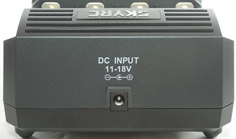
On the back is a single power connection for 12V, or rather 11V to 18V.
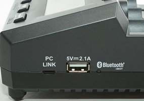
On the side of the charger are two usb connections, one micro for a PC link and one full size for a usb power output (This is not a power bank). There is also a led to indicate Bluetooth connection to a smartphone.
The PC link can be used to control the charger and to update the firmware in the charger.
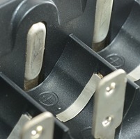
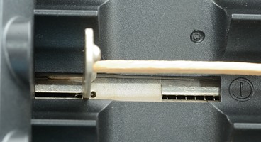
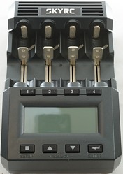
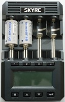
The slots uses the usual slider style, but the size is larger than usual, generally it works well, but flat top cells can be a bit tricky go get working. The two outer slots will fit D cells!
They support from 29mm to 72mm, this means even the longest protected 26650 batteries.
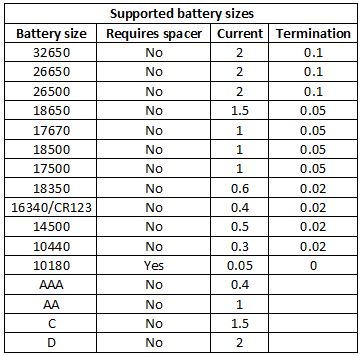
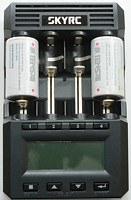
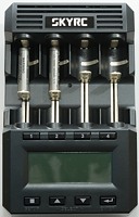
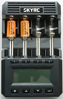
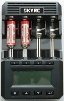
The charger can handle 72mm long batteries, inclusive flat top cells (May require a bit of tinkering), this means all protected cells.
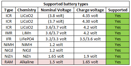
RAM cells are not support "out of the box", but requires a special code from SkyRC.
User interface
With all the function in this charger it has a lot of user interface with lot of settings. Generally the (advanced) user interface works fairly well, but I have one complain:
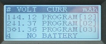
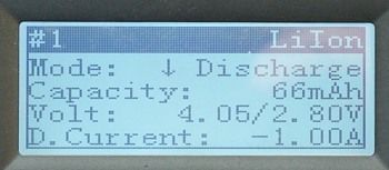
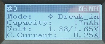
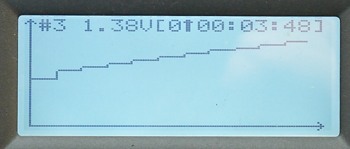
I have just put 3 batteries in the charger and it shows this, what will it do with the batteries? The second column shows some symbols, the arrow down is discharge and the * is break_in, but what chemistry, current (capacity for break_in) have I selected? I must either remember it, have a note besides the charger or use a few keypresses to check it.
Pressing the 1, 2, 3 or 4 key will show the information:
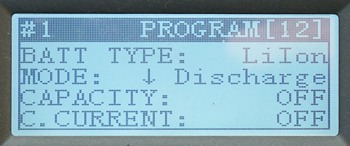
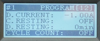
I can move between all slots with the number keys and check the first four lines of the program, pressing the arrow keys will change between programs for that slot. To see more of the program I have to press enter and arrow down. When finished with looking at the program and maybe modifying them I need to hold enter down to get back to the first screen again.
Pressing enter on the first screen will start charging all slots, holding down a number key will start charing that slot.
While charging I can use the number keys to show actual charge/discharge information for each cell:
Two examples of the data display, scrolling down with the arrow key will show more information.
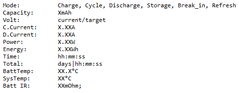
Here I have listed the full contents of the data display.
To return to the main screen enter must be pressed.
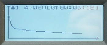
Pressing one of the arrow keys will show curves, repeatedly pressing arrows will change between the different batteries. Pressing enter will return to main screen.
With no batteries in the charger holding stop down will show the system menu:
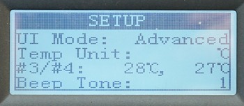
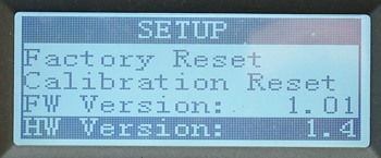
In this menu the user interface can be selected, preferences can be selected, version can be read.
Lets get back to user interfaces again. The charger has 3 different interfaces:
In my opinion only the advanced is interesting.
The dummy interface makes it fairly simple. The charger will automatic select LiIon or NiMH and you only have to select current, but this requires pressing a number key, before using the arrow keys. To start charging enter must be pressed. This UI can only charge.
The simple interface is a very simplified version of the advanced interface, in my opinion to many settings is missing when using this interface. At least it gives access to all the functions on the charger.
Both simple and dummy uses default settings for maximum charge time and capacity, that cannot be change, but these defaults do not always work!
Settings in simple user interface:
The advanced user interface gives access to all the capabilities of the charger, but requires some time and understanding to get the programs right (I have written a small guide, it is near the bottom of this review).
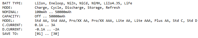
Settings in advanced user interface:
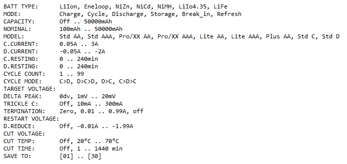
Only one of CAPACITY/NOMINAL/MODEL will be visible. DELTA PEAK and TRICKLE C is shown for NiMH and TERMINATION for LiIon.
When adjusting charge current the termination current will also be adjusted to 10% of charge current, i.e. always remember to change it after adjusting the current.
CAPACITY, CUT TIME and CUT TEMP are safety settings and can be used to terminate a charge on abnormal conditions.
All the system settings:
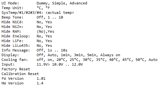
RAM cannot be enabled, it requires a secret sequence and SkyRC will only tell it to people with a receipt for RAM cells.
I do not really see the point in hiding some chemistries on this charger, you do not have to select chemistry each time you charge a cell, only when making a program
PC interface
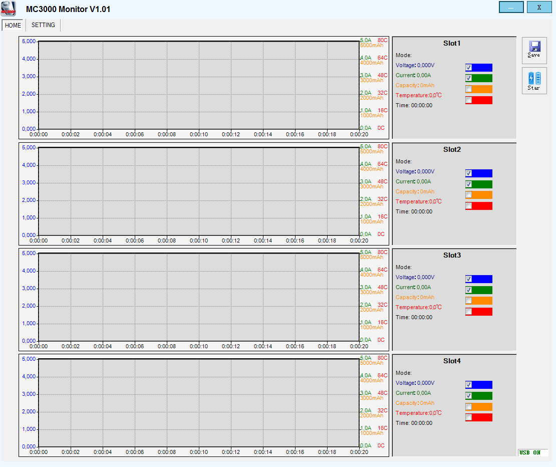
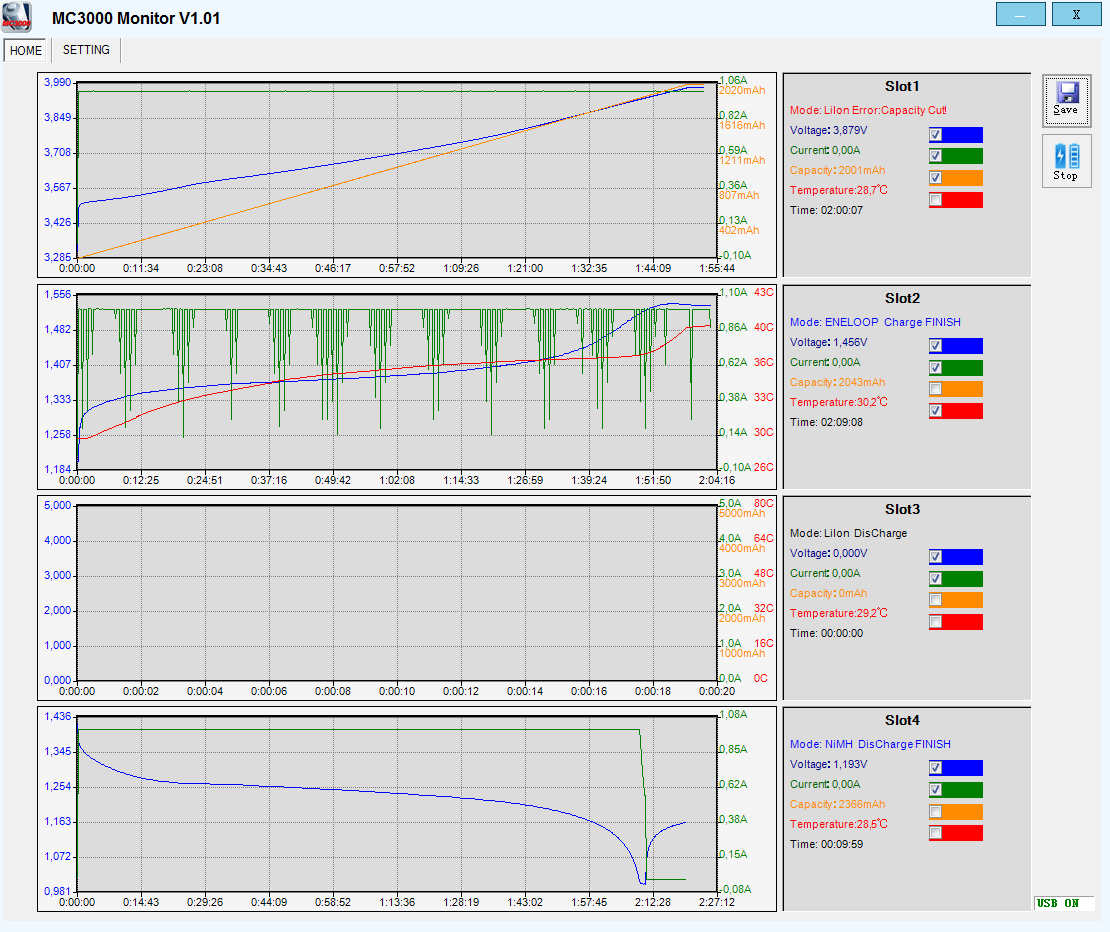
The charger has a PC interface and it is possible to download a program from SkyRC to control the charger (Click on images for full size):

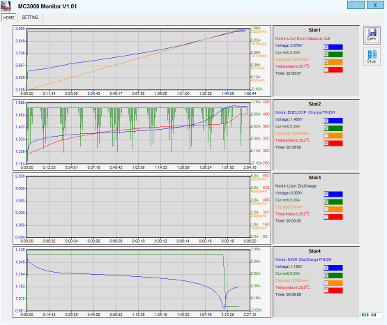
The program looks this way when started. It has a curve area, some values and checkmarks to enable different curves.
The layout is fixed in size and this means you need a screen with at least 1000 dots in height to see all charts.
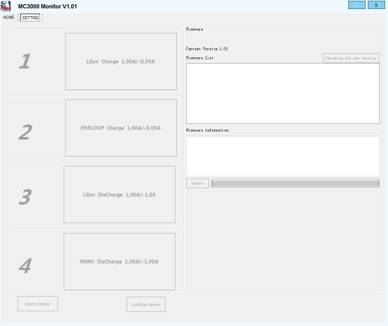
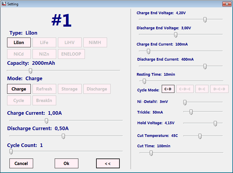
On the settings page the actual program for each slot in the charger can be seen and it is possible to update the charger software. From this program you can either use the program number that is selected on the charger or make your own settings.
Clicking on one of the charger settings will open a popup (If the charger is idle). There is a button to load the actual programs from the charger (Send to device will not change the programs only override it temporary).
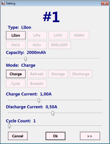
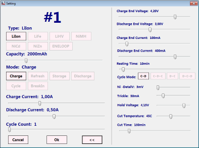
It is possible to adjust all the charger parameters in this popup. The initial popup is the small version, but pressing the >> symbol will open the full popup.

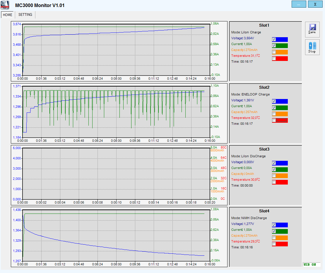
Here I have started charging on 2 slots and discharging on 1 slot. While this is running I can enable/disable curves, the curves are saved, even when not displayed, this means that enabling a curve will show the full curve from the start.
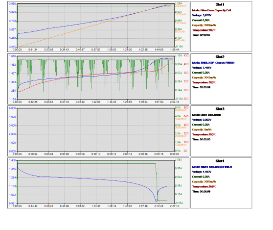
Here is the full charge curves, with the LiIon cell I had specified to low capacity and it was stopped when that capacity was reached.
With NiMH the curves shows the pauses used to measure voltage, it would be nice if it was possible to hide these pauses.
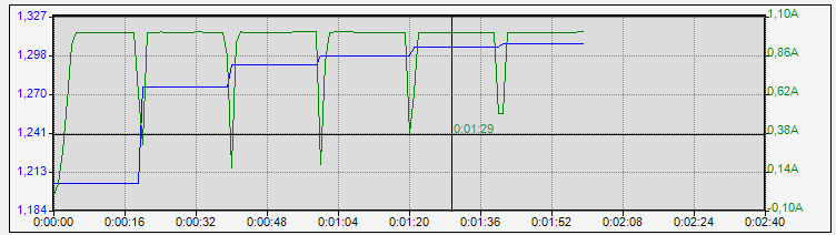
A nice little detail is that some measuring lines are show when the cursor is moved inside a chart.
In this chart it is also possible to see how the voltage measurements are done each time the current is turned off for NiMH (The voltage increases each time the current is off).
The save button will save an image with the same size as the layout on the screen, but it do not include UI elements and it uses transparent background. There is a problem with some of the text, it is not very readable.
If you want to play with the data, the software saves a csv file with all the data (very nice). This is file saved in the same directory as the exe file and not where the screen dump is saved (oops)!
One nice detail with the software is that it does not need a driver or any installation, just plug the charger in, unpack the software and run it.
But the software is not perfect, I have tried to record a LiIon refresh, but I only get the first 35 minutes on the pc?
The free software DataExplorer also has support for this charger.
Smartphone interface
I could not test this, the charger would not work with my HTC one smartphone, a small Samsung smartphone or with my Sony pad.
That has prevented me from testing it.
Measurements
- When not powered the charger will discharge with about 4mA
- When powered the charger will discharge with about 0.4mA.
- Any voltage above 0.10 volt will register as a battery and show voltage on display.
- In the 0.10V to 4.50 volt range the charger was within 0.01 volt of my DMM (Very good).
- Charge current is within 0.01A of my DMM (#1 not included) (Very good).
- Discharge current is within 0.02A of my DMM (#1 not included) (Very good).
- Voltage is always updated, also when charging is finished.
- Restarting charging when voltage drops is configurable.
- Trickle charging is configurable.
- Charging voltage is configurable.
- -dv/dt sensitivity is configurable.
- Unloaded power consumption is 1.1 watt from 12V with display on and 0.7 watt with display off.
- Unloaded mains power consumption with display on is 2 watt, with display off and 1.4 watt (Power supply alone is 0.29 watt).
Dummy mode user interface
In this mode you just put LiIon or NiMH cells in the charger and select current, chemistry and charge parameters are automatic selected.
%20%231.png)
First battery in dummy mode is a 3100mAH LiIon cell where I selected 1A charge current. It did not really work because the charger has a default time limit of 3 hours on all charging (In advanced mode I can change it, but not in dummy or simple mode).
To charge LiIon in dummy mode this means I either has to accept a fairly high charge current, accept partial charged cells or charge two times.
I hope this get fixed in next software update.
%20%231.png)
With NiMH AA/AAA the 3 hours limit is much more acceptable and it did a fine charge. When finished it uses a low trickle charge current, because I mostly uses LSD (Low self discharge) cells, I would have preferred it without trickle charge (Using advanced mode it can be disabled).
Charging real C or D cells in dummy mode will probably hit either the time limit or the capacity limit.
Charging LiIon
%20%231.png)
First test is a normal LiIon charging at 1A. The current is very precise at 1A, until the charger goes into constant voltage phase. The termination is at 50mA, this is not the default for the charger, but something I selected.
This charge curve is just about a perfect CC/CV charge.
The display shows 2926mAh charged into the battery, this is very close to my equipment.
%20%232.png)
%20%233.png)
%20%234.png)
The 3 other channels looks about the same, #2 is a bit slower because the cell goes into the CV phase earlier due to higher internal resistance and takes longest to charge (i.e. it is a bit more worn).
The display shows: 2950mAh, 2961mAh, 2858mAh
%20%231.png)
With freely adjustable charger current I can charge these cells at their maximum charge current and save some time.
Nearly all 18650 cells have a maximum charge current at 1.5A or higher.
%20%231.png)
It is also possible to do a very slow charge, just remember to disable time check.
Display shows: 2834mAh
%20%231.png)
With the 2600mAh cell I used the standard termination current (10% of charge current, i.e. 100mA in this case).
Display shows: 2498mAh
%20%231.png)
No surprise with this cell.
%20%231.png)
Charging a 14500 cell with 20mA termination works perfectly.
Display shows: 756mAh
%20%231.png)
My very old and nearly completely worn out cell is also handled perfectly by the charger.
%20%231.png)
This charge can also charge with very low current, i.e. handle small LiIon cells like 10180. Here I am charging with 50mA and it is a stable 50mA current (Very nice). I did use "Zero" termination, it looks like it is close to the 10mA termination.
%20%231.png)
This worn cell is easily handled by the charger.
.png)
Four cells at 1A is easy enough for the charger.
.png)
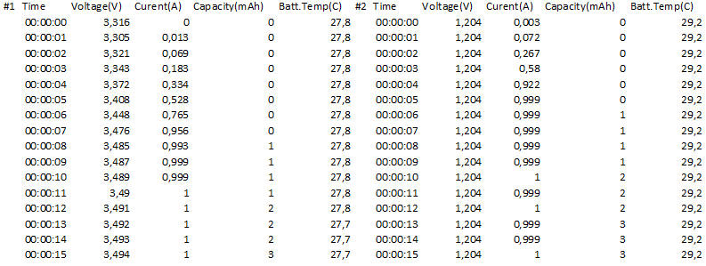
Here I fast charged some cells using the full power of the charger. Input current did go slightly above 5A with a 12V supply.
I did set a fairly low termination current to secure the cells would be filled, using the default higher termination current would only have lost me a few percent of the capacity and saved me 20 minutes in charge time.
The cells started at a fairly low voltage and the charger used slow charge until they reaced 3.2 volt, then it turned on the full current.
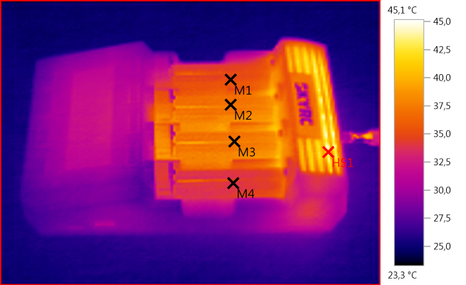
M1: 35,1°C, M2: 37,2°C, M3: 37,8°C, M4: 34,1°C, HS1: 45,1°C
Charging with 1A, the fan did not start during this charge.
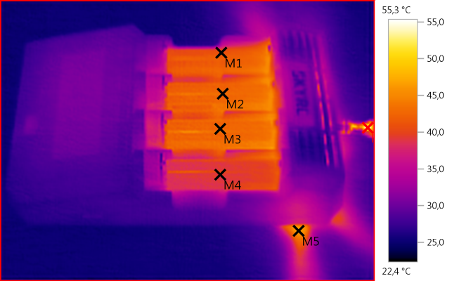
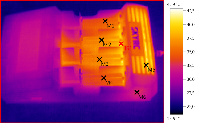
M1: 41,1°C, M2: 43,1°C, M3: 42,7°C, M4: 39,1°C, M5: 46,6°C, HS1: 55,3°C
Charging with 3A, here the fan started, as can be seen on the table and on the much cooler charger. Remember that it is possible to adjust when the fan starts, i.e. how hot the charger must be.
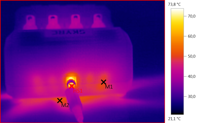
M1: 48,9°C, M2: 51,0°C, HS1: 73,8°C
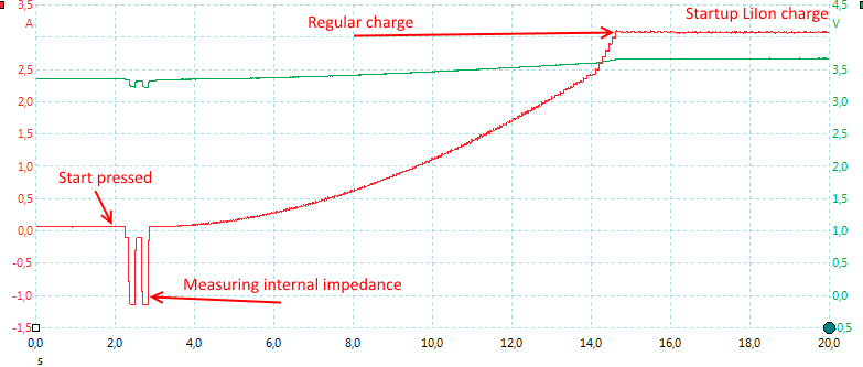
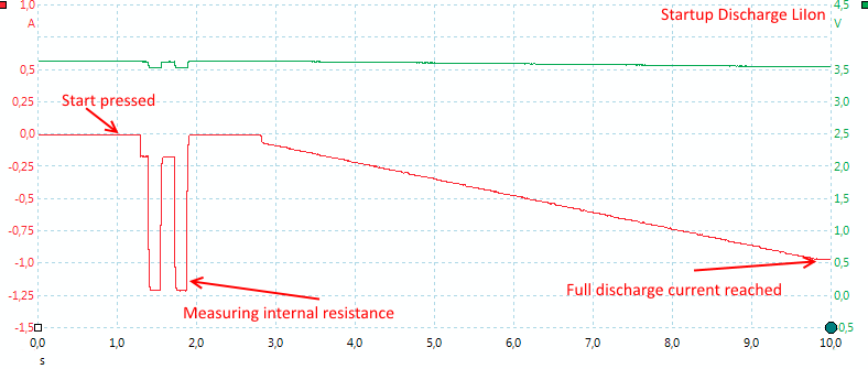
When the start button is pressed the charger will measure internal resistance of the batteries, then it will slowly ramp the current up to selected charge current. When charging LiIon is will use constant current all the time.
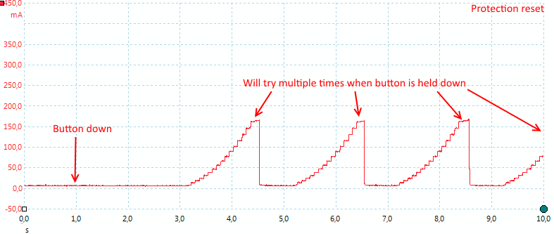
The charger has a special protection reset, hold down the number button for an empty slot and it will pulse the current.
Charging LiIon 4.30V and 4.35V
The charger has a 4.35V LiIon setting, inside this setting it is possible to adjust the charge voltage to either 4.35V or 4.30V (Any value from 4.10 to 4.40) when using advanced UI.
%20%231.png)
I tested with a 4.35V cell and 4.35V charge voltage, everything worked as expected.
Charging LiIon 3.60V i.e. LiFePO4 cells
%20%231.png)
%20%231.png)
Both LiFePO4 curves looks fine.
Discharging LiIon
The charger has a discharge limit of 15 watt, this means it will either do 1 LiIon at up to 2A or 2-4 LiIon at up to 1A.
%20%231.png)
The discharge function will empty a battery, this is useful for measuring capacity. On this charger the end voltage can be selected, I am using 2.8 volt.
Display shows: 2915mAh
%20%232.png)
%20%233.png)
%20%234.png)
Not much difference between channels.
Display shows: 2986mAH, 2914mAh, 2909mAh
%20%231.png)
The charger has a useful function when discharge must be until a specific current (Like a led that will work down to 50mA at 2.8 volt). Using the D.REDUCE option the charger will continue to discharge until both voltage and current is below the setting.
Look at the much lower voltage recovery here, even though I started discharged at 2A, the final current was only 50mA.
.png)
Due to the power limit in the charger it can only discharge multiple LiIon batteries with 1A (A single cell can be discharge with 2A).
Discharging multiple LiIon cells at full current will produce a lot of heat and it can overheat the charger, this is not a problem for the charger, it will just reduce current. To avoid that be sure to place the charger on a hard surface with lots of free air around it, anything close to the back part of the charger means some of the hot exhaust air will be sucked in again, making the charger warmer. It is also possible to reduce discharge current or only discharge 3 cells.
As can be seen on the curve I did not see any reduction of current on channel #1, but I do not know if the charger reduced current on some of the other channels.
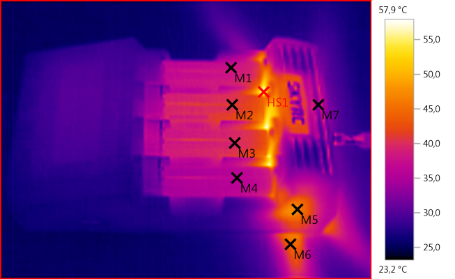
M1: 38,0°C, M2: 41,1°C, M3: 39,5°C, M4: 36,5°C, M5: 46,8°C, M6: 44,6°C, M7: 33,9°C, HS1: 57,9°C
As usual when discharging batteries a lot of heat is generated, here it is obvious that the fan is on and that the airflow is down.
The construction with the heatsink and the fan in the back of the charger keeps the batteries fairly cool during discharge.
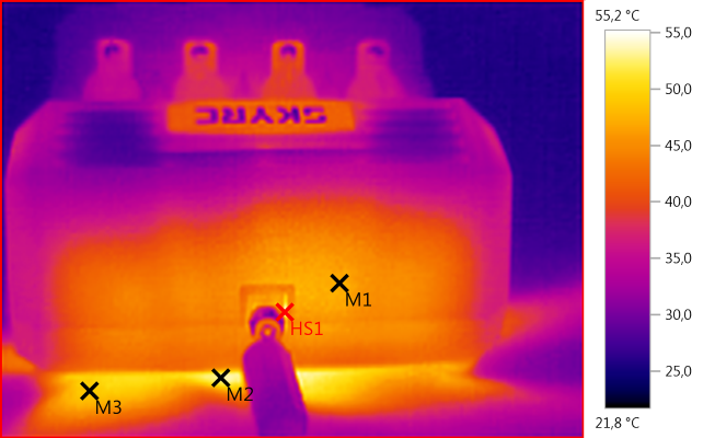
M1: 47,1°C, M2: 53,1°C, M3: 49,2°C, HS1: 55,2°C
The table below the charger is heated a bit, using the foldable legs on the charger would reduce this.
When start is pressed in discharge mode the charger will first measure the internal resistance of the cells, the slow ramp up the discharge current. There is no pulsing, it uses a steady current.
Other functions LiIon
The charger can do a couple of other functions on LiIon.
%20%231.png)
When storing LiIon batteries for months or more, it is best to start with them in the 3.7 to 3.8 volt range. This charger has a special function for charging the batteries to that voltage (As usual the actual voltage is adjustable).
%20%231.png)
Or discharging, if the battery is full. Here the D.REDUCE function would have been nice, but it cannot be enabled (This has been fixed in a software upgrade).
%20%231.png)
The cycle function can be used to test capacity over time (i.e. how long does it take to wear a battery down), it is possible to do up to 99 cycles! Depending on the settings in the charger it can either start with charge or discharge and finish with charge or discharge.
Display: 2834mAh, 2835mAh, 2826mAh (It is possible to read the value for each cycle).
%20%231.png)
The refresh function will do one cycle and then report the capacity. Here the function is always charge, discharge, charge.
Charging NiMH
%20%231.png)
A nice -dv/dt charging. All the pulsing it not due to pwm, but because the charger measures voltage with current off.
Display shows: 2004mAh
%20%232.png)
%20%233.png)
It is the same on the other 3 slots.
Display shows: 2043mAh, 2007mAh, 2019mAh
%20%231.png)
Display shows: 2644mAh
%20%231.png)
Display shows: 2508mAh
%20%231.png)
This cell was stopped due to the default 3 hour time limit. The cell is about full, but there is no voltage drop yet (i.e. -dv/dt signal).
%20%231.png)
When charging a AA cell at 0.2A the charger will not terminate (this is no surprise), using the capacity setting I avoid continuous over charge, but stops soon after the battery is full (if I started with an empty battery).
%20%231.png)
A AAA cells is handled without any problems.
%20%231.png)
The charger was fairly fast at detecting a full cell (for a -dv/dt charger).
%20%231.png)
If you want to handle the batteries very careful, it is possible to use voltage termination, but you will not get the batteries filled completely. This charge method requires placing the termination voltage at the correct value, even a little bit too high will be hard on the batteries. Use capacity and timer cut settings can limit the damage if that happens.
Display shows: 1749mAh
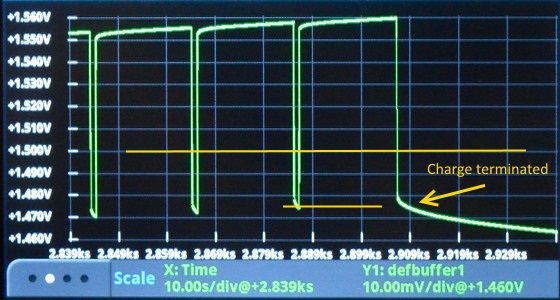
On the above my termination setting was 1.5 volt, but looking at the curve it looks like it terminates slightly below that value. Using my most advanced DMM I can confirm that it is the case. The termination setting was 1.5 volt, i.e. the top yellow line, but it terminated at the bottom yellow line. The strange thing is that the display also shows the value for the bottom yellow line (I did not check exactly at the termination).
%20%231.png)
Here I tried with a 0dv/dt setting, with this cell it gives a fast termination when the cell is full. Sometimes it may terminate at the start of the charge, due to the cell heating up.
.png)
There is no problem charging 4 cells simultaneous.
M1: 34,5°C, M2: 37,1°C, M3: 36,3°C, M4: 34,5°C, M5: 38,1°C, M6: 32,5°C, HS1: 42,9°C
Charging with 1A
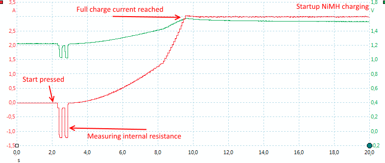
As usual the charger starts by measuring the internal resistance, then it slowly ramps current up to select level.
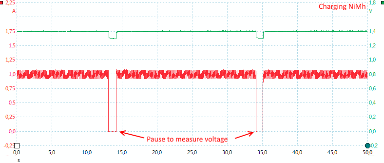
During NiMH charge the charger will pause to measure voltage (This is not pwm).
Discharging NiMH
%20%231.png)
The discharge curve looks fine, both the discharge voltage and current can be adjusted.
Display shows: 1853mAh
%20%232.png)
%20%233.png)
%20%234.png)
Display shows: 1878mAh, 1870mAh, 1868mAh
.png)
Here I discharge 4 NiMH batteries, this does not generate much heat. The charge I did just before heated the batteries considerable more as can be seen at the start of the temperature trace.
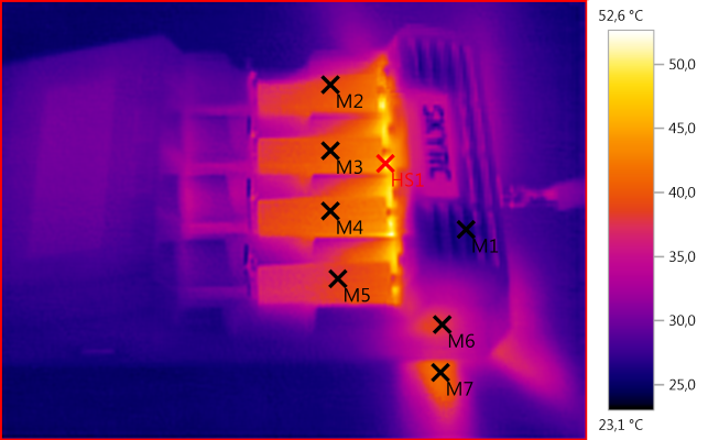
M1: 25,8°C, M2: 39,1°C, M3: 40,2°C, M4: 40,5°C, M5: 38,4°C, M6: 38,0°C, M7: 41,4°C, HS1: 52,6°C
Discharging 4 eneloops with 2A, fan is on.
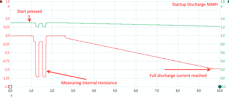
No surprise here, first the internal resistance measurement, then slowly ramping the current up. There is no pulsing when discharging.
Other functions NiMH
%20%231.png)
The refresh function will charge, discharge and charge again, the display shows the discharged capacity.
Display shows: 1835mAh
%20%231.png)
The standardized break-in charge, it takes a very long time. Sadly the display shows charged capacity and not discharged capacity (Oops).
Display shows: 3795mAh
I have not tested the cycle function for NiMH, see LiIon for a test.
Internal Resistance
The charger measures internal resistance of a battery before starting on an operation.
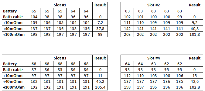
This is a very good result, the correct values in the result column are 10-40-100 and all slots are fairly close to that and the variance between repeat measurement is fairly low.
What I analyze above is mostly the measuring circuit, not the variations in contact resistance or the total circuit resistance.
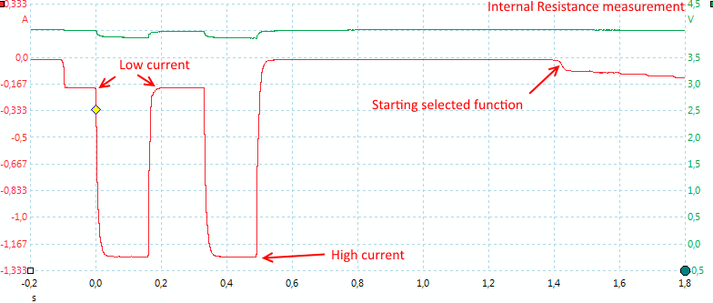
Here is a closer look at the RI measurement sequence. It looks like the charger uses two currents for the measurement, in most cases this will give same result as one current, but in a few cases this will give a better result than one current (See more here).
Calibration
It is possible and fairly easy to do your own calibration, if you have a good dmm. I have not done any calibration before doing the above test, but I have checked the factory calibration using a Keithley DMM7510 (Note: This is not a production charger):
Discharging with 1A according to charger, correct value is:
Current channel #1: 1.0135
Current channel #2: 0.9980
Current channel #3: 1.0060
Current channel #4: 1.0060
First number is charger, second number is DMM, 3 number is difference
Voltage channel #1: 4.116 4.123 (-0.007)
Voltage channel #2: 4.113 4.123 (-0.010)
Voltage channel #3: 4.116 4.123 (-0.007)
Voltage channel #4: 4.123 4.123 (0.000)
The current calibration is within 1.5% and voltage is within 0.3%, this matches fairly well with the result from the two production chargers I bought:
Unit #38 (Last digits of serial number)
Current channel #1: 1.0130
Current channel #2: 1.0070
Current channel #3: 1.0135
Current channel #4: 1.0124
First number is charger, second number is DMM, 3 number is difference
Voltage channel #1: 4.141 4.146 (-0.005)
Voltage channel #2: 4.137 4.146 (-0.009)
Voltage channel #3: 4.140 4.146 (-0.006)
Voltage channel #4: 4.146 4.146 (0.000)
Unit #26
Current channel #1: 1.0085
Current channel #2: 1.0020
Current channel #3: 1.0162
Current channel #4: 1.0170
First number is charger, second number is DMM, 3 number is difference
Voltage channel #1: 4.139 4.146 (-0.007)
Voltage channel #2: 4.136 4.146 (-0.010)
Voltage channel #3: 4.138 4.146 (-0.008)
Voltage channel #4: 4.146 4.146 (0.000)
I did calibrate both units and now the error is about 1 on the last digit, but is expected to change with temperature and age.
USB output
- USB output is coded as Sony.
- This is not a power bank function, only a usb charger output.
- Unloaded power consumption is 1.1 watt from 12V with display on and 0.7 watt with display off.
- Unloaded mains power consumption with display on is 2 watt, with display off and 1.4 watt (Power supply alone is 0.29 watt).
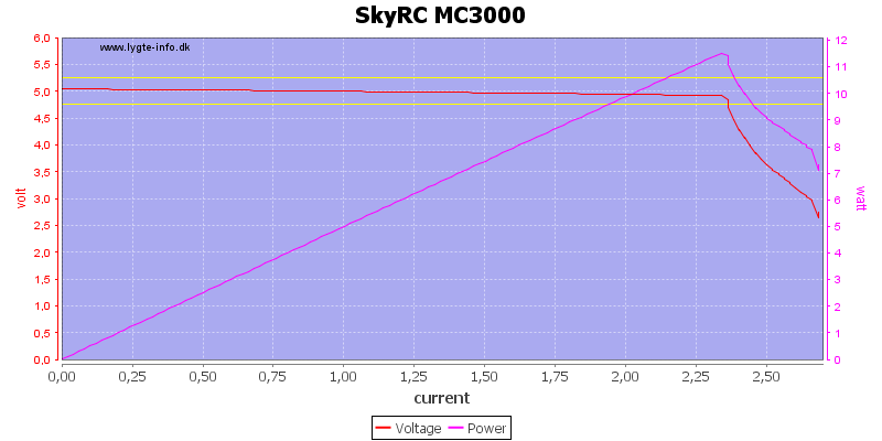
The output is rated for 2.1A and the output starts limiting power at 2.3A (nice).
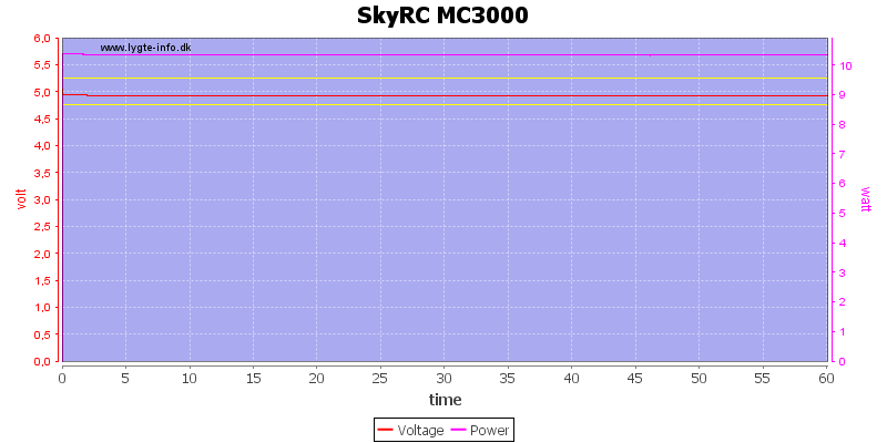
Running 1 hour with 2A load was no problem.
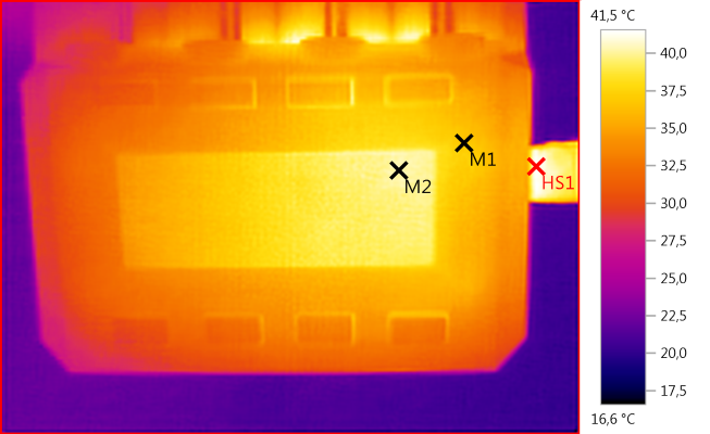
M1: 36,8°C, M2: 40,2°C, HS1: 41,5°C
The electronic for the usb out is placed below the display, as can be seen from the heat.
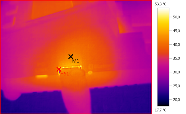
M1: 42,0°C, HS1: 53,3°C
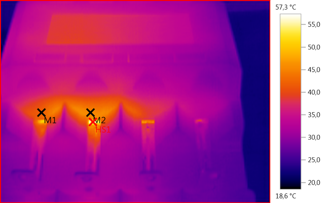
M1: 42,2°C, M2: 45,1°C, HS1: 57,3°C
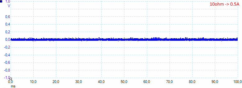
There is not much noise in the usb output: 19mV rms and 114mVpp
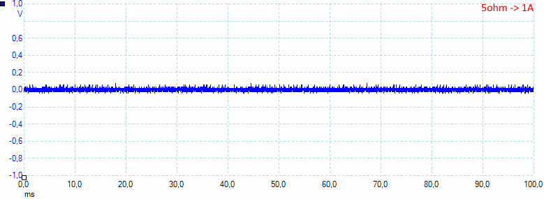
Increasing to 1A do not change it: 19mV rms and 117mVpp
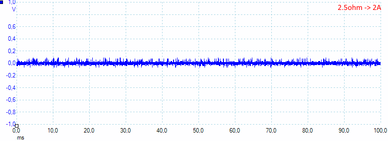
At 2A the noise is increased slightly, but still very low: 21mV rms and 161mVpp
A look inside
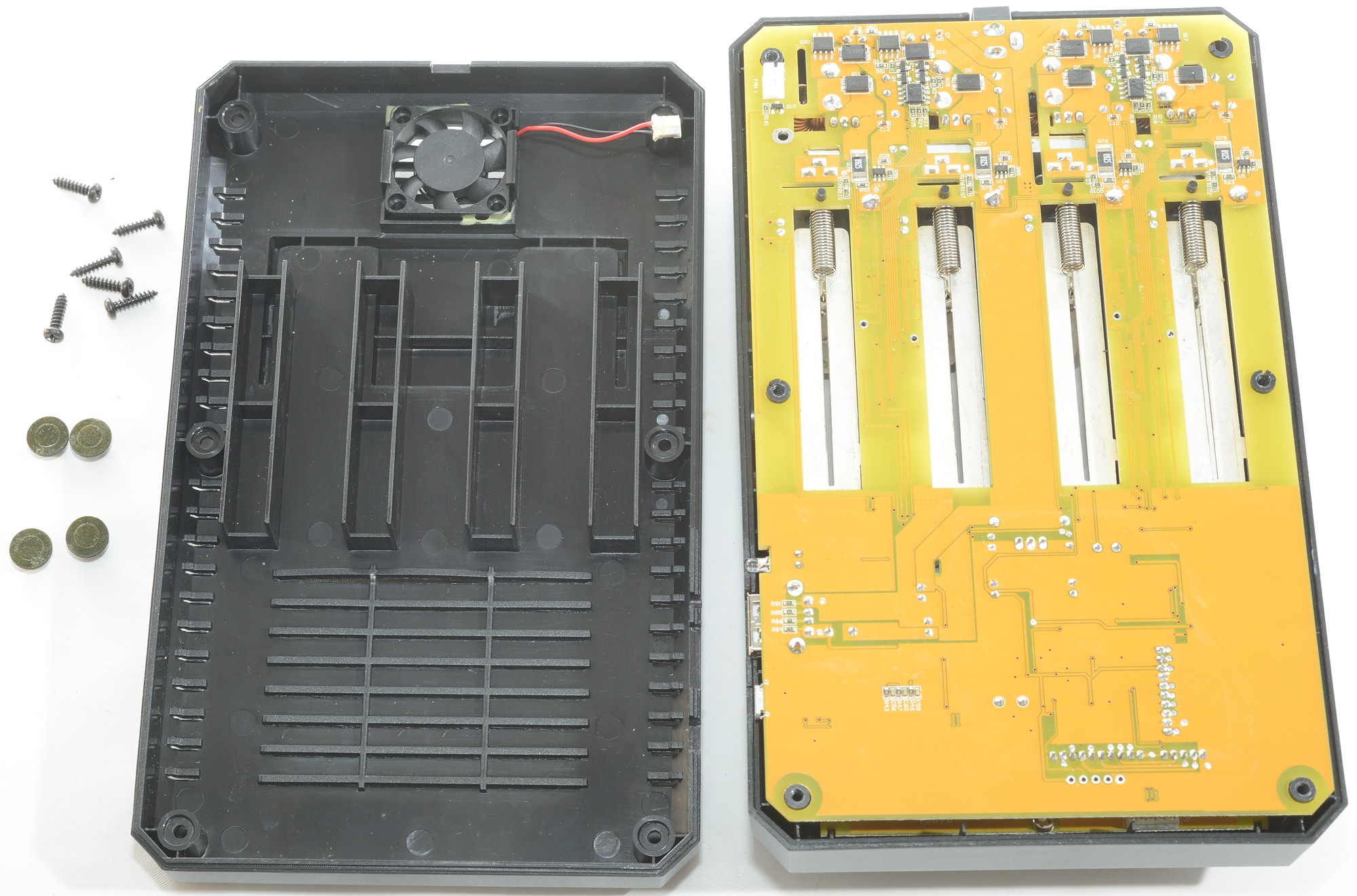
Because there has already been a couple of pictures posted of the inside, I decided to do a teardown.
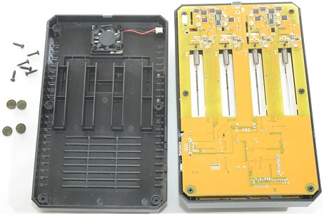
A total of six screws must be removed to open it. The small fan has a connector to the circuit board (nice).

The main circuit board can be easily removed, everything is with connectors, but getting everything together again is not that easy!

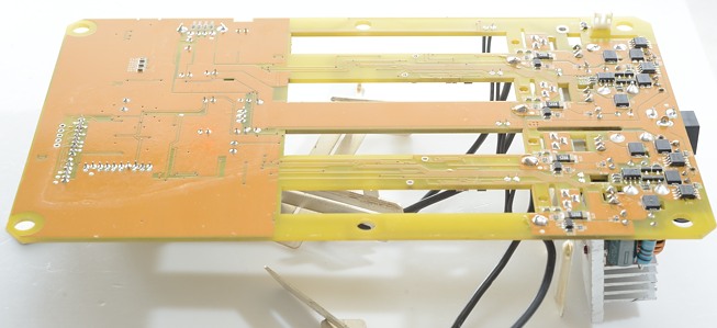
The full circuit board, I will look at it in detail shortly. The cute animal is a reference to the guy that helped SkyRC with ideas to design the charger.
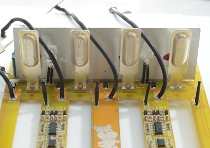
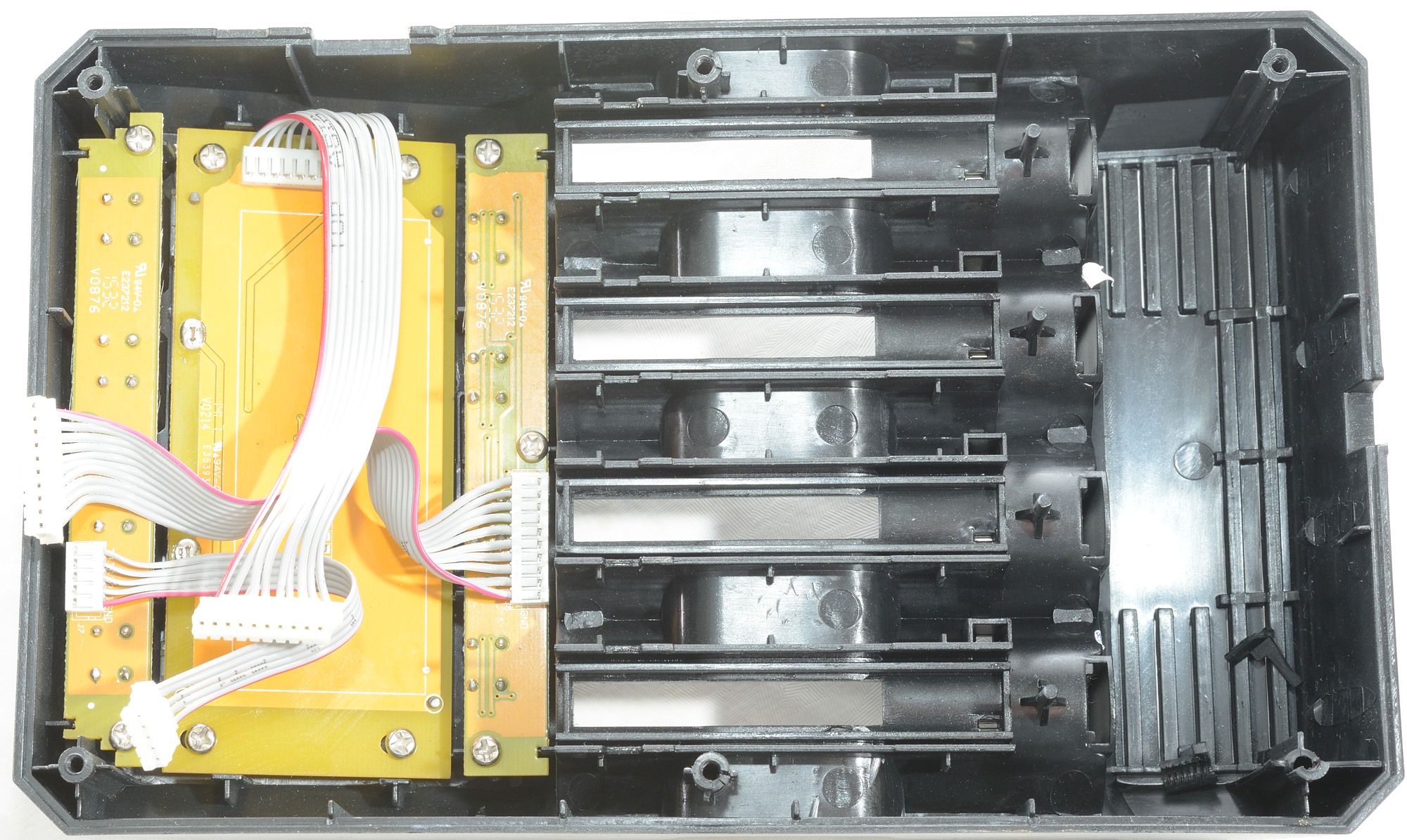
Here the heatsink and the 6 thermo sensors can be seen. Two is placed against the heatsink and four will match holes in the top part and be placed very close to the batteries. That means they will not measure the battery temperature, but will be an indication on how warm the batteries are.
The wires used for the battery connection is fairly thick, this means the voltage readout on the charger will be very close to the actual battery voltage during charge and discharge.

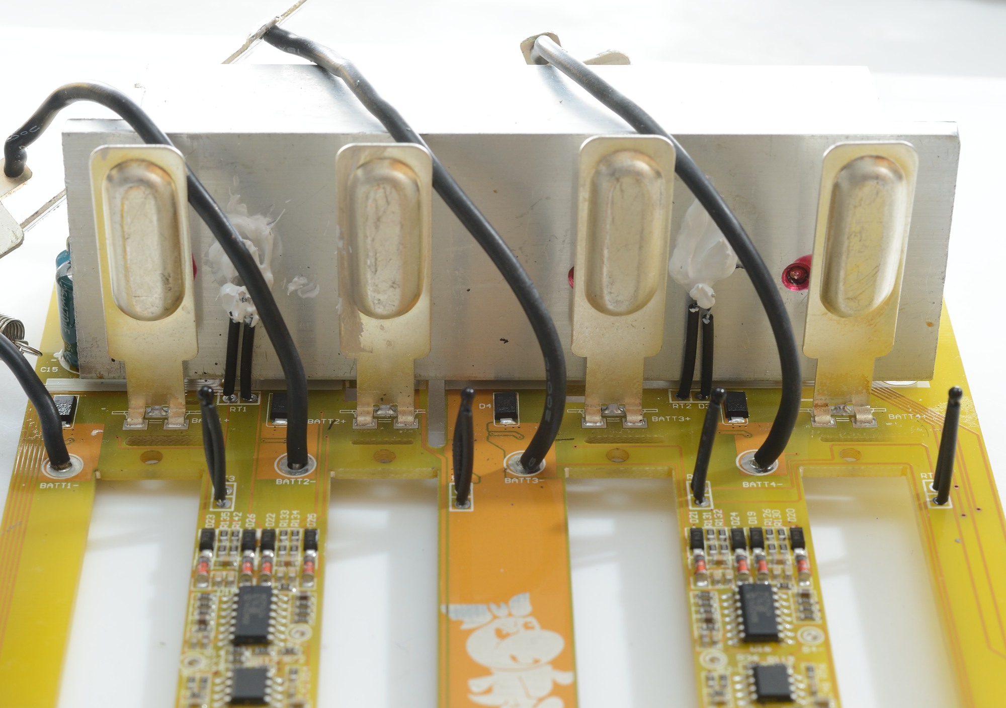
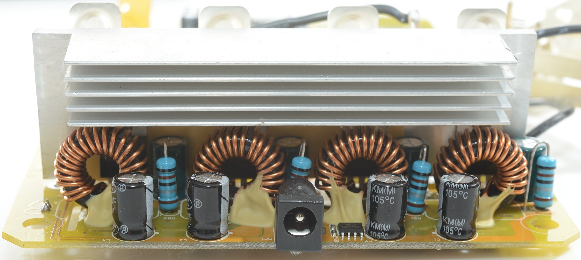
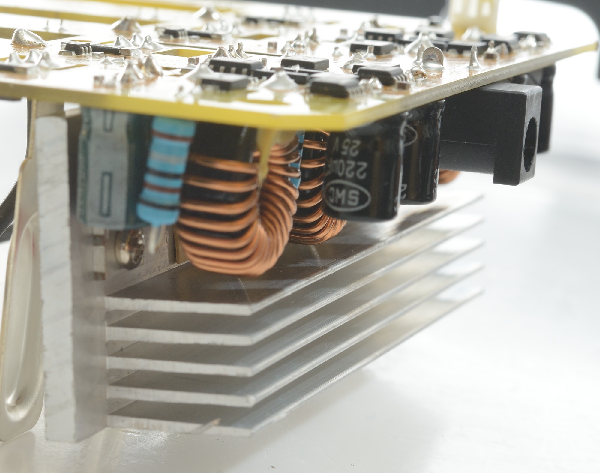
A closer look at the heatsink and the four switching charge circuits. Behind each inductor is a transistor, that is mounted on the heatsink. This transistor is probably used when discharging batteries.
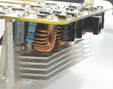
The actual heatsink design is not made for best cooling, there are few holes in the circuit board the fins are horizontal. A vertical fin placement is usual better for cooling, because the air will the flow up over the full heatsink area.

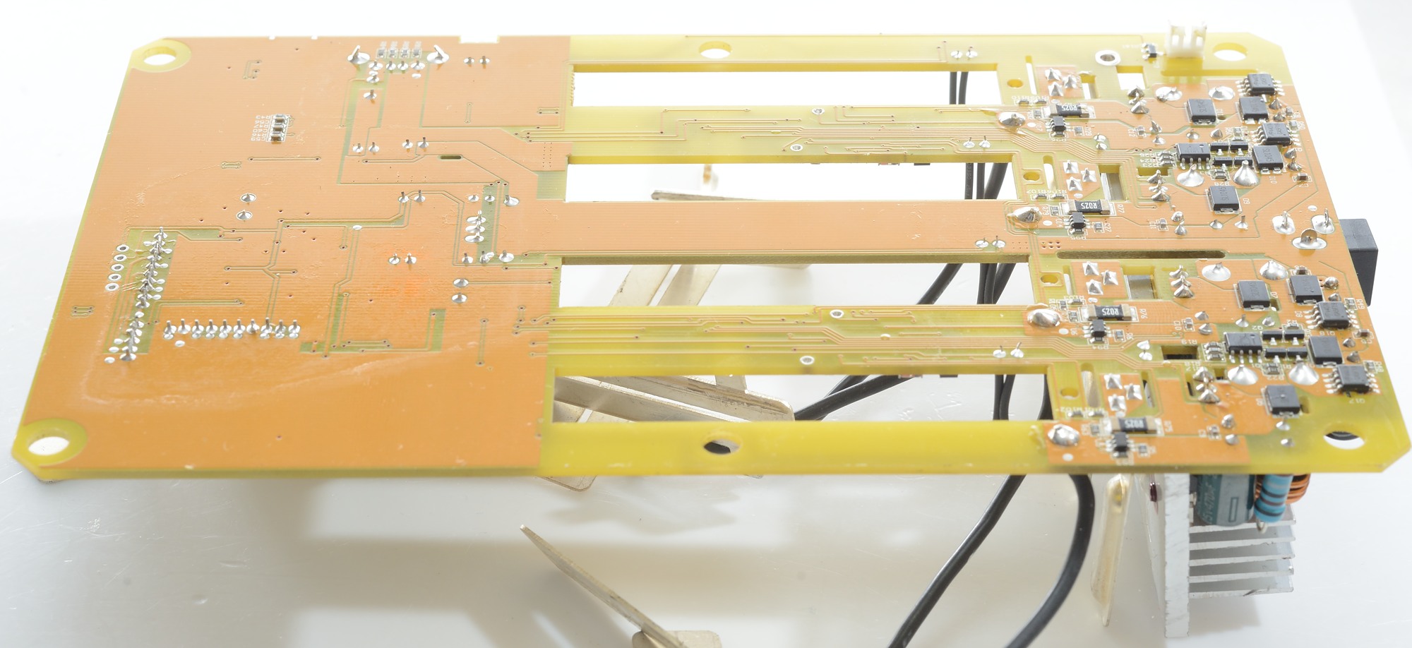
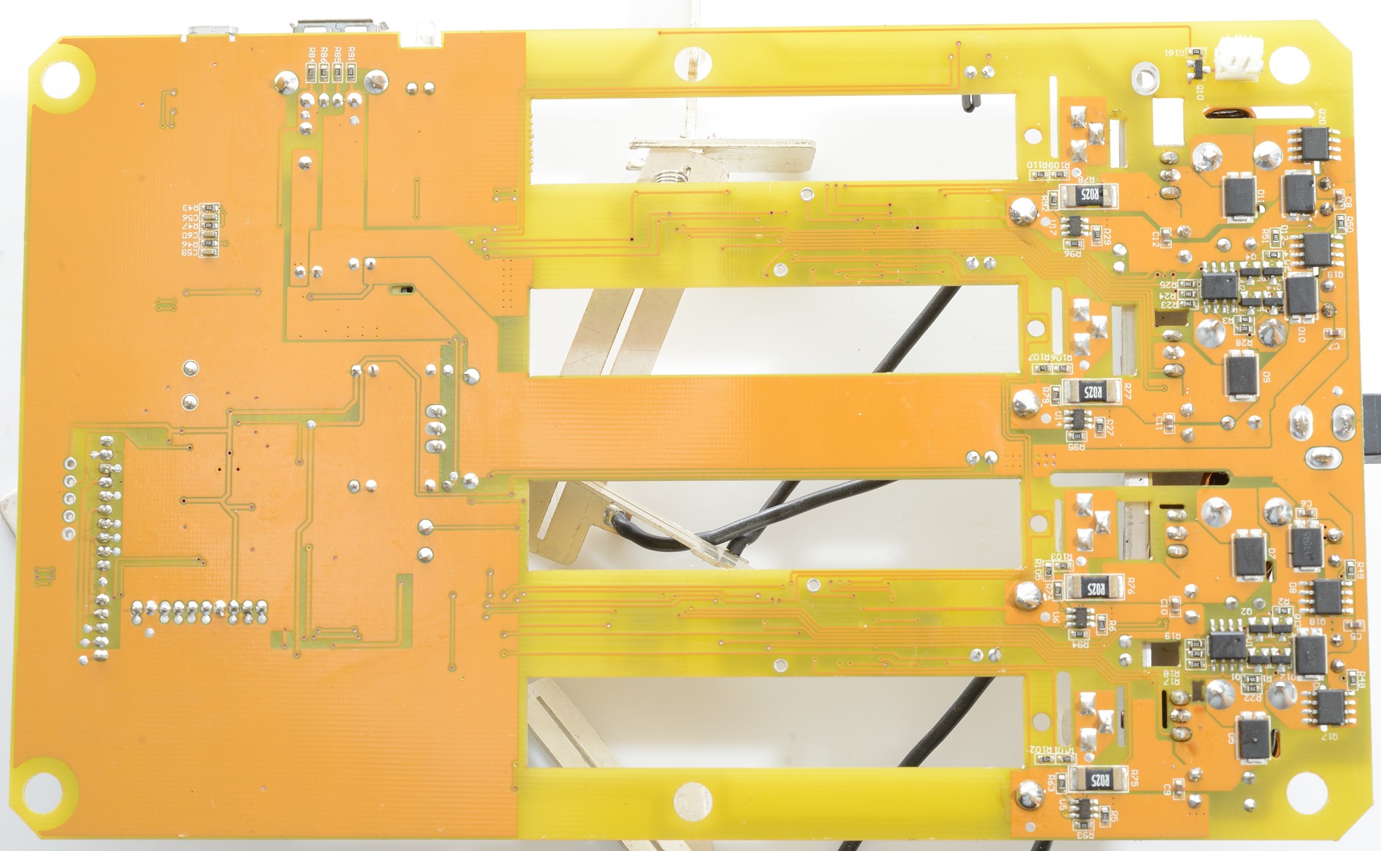
The bottom of the circuit board has some electronic below the heatsink, this is the rest of the four switching circuits.
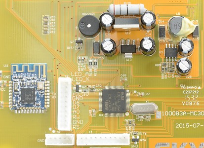
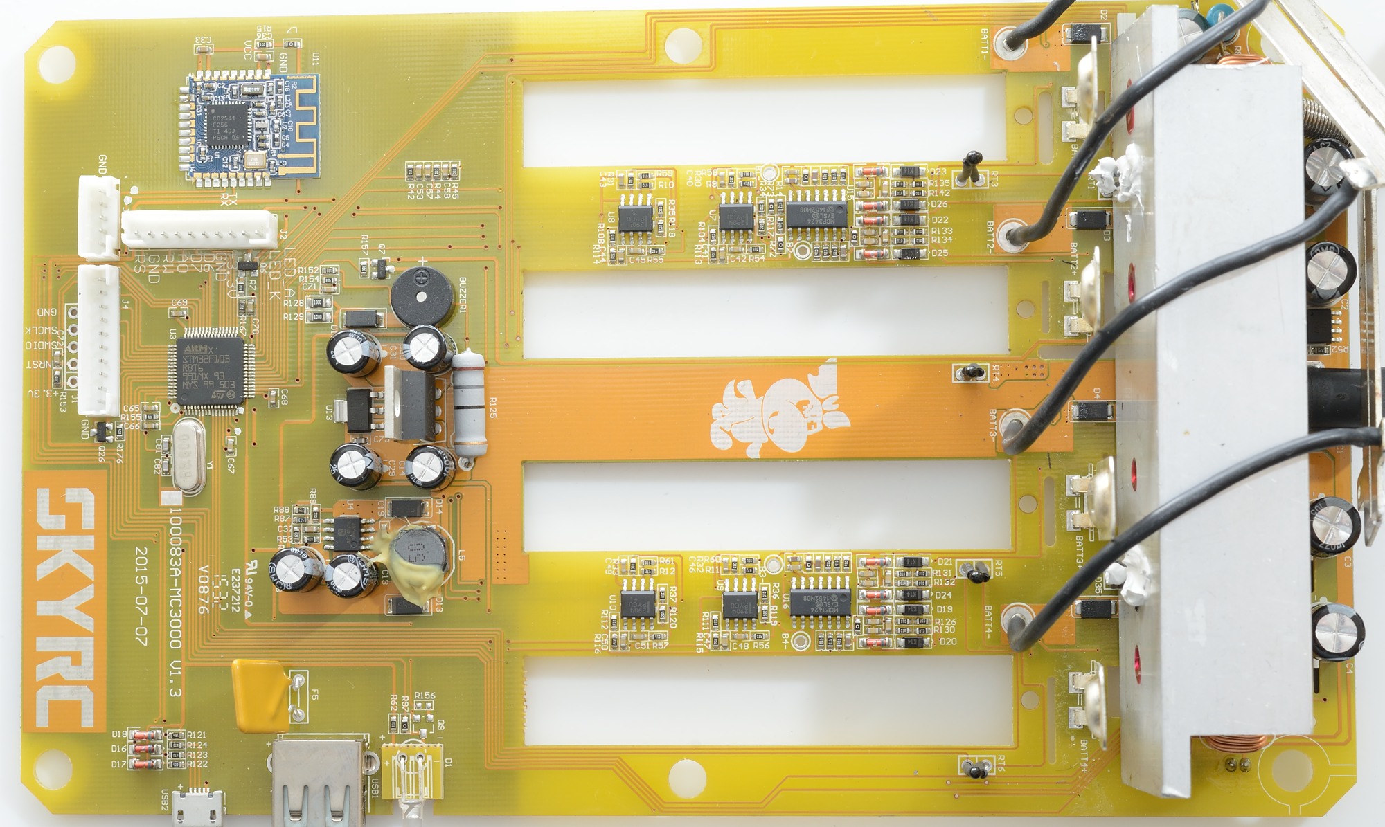
Getting close to the circuit. Here is the main processor STM32F103RBT6 it is an ARM processor that has 128k flash, 20k ram, 51 I/O pins, 16 ADC's, SPI, i2C, USB, 16 pwm 16 bit. This is a fairly powerful processor for a charger.
The blue circuit board with the CC2541 is the Bluetooth module
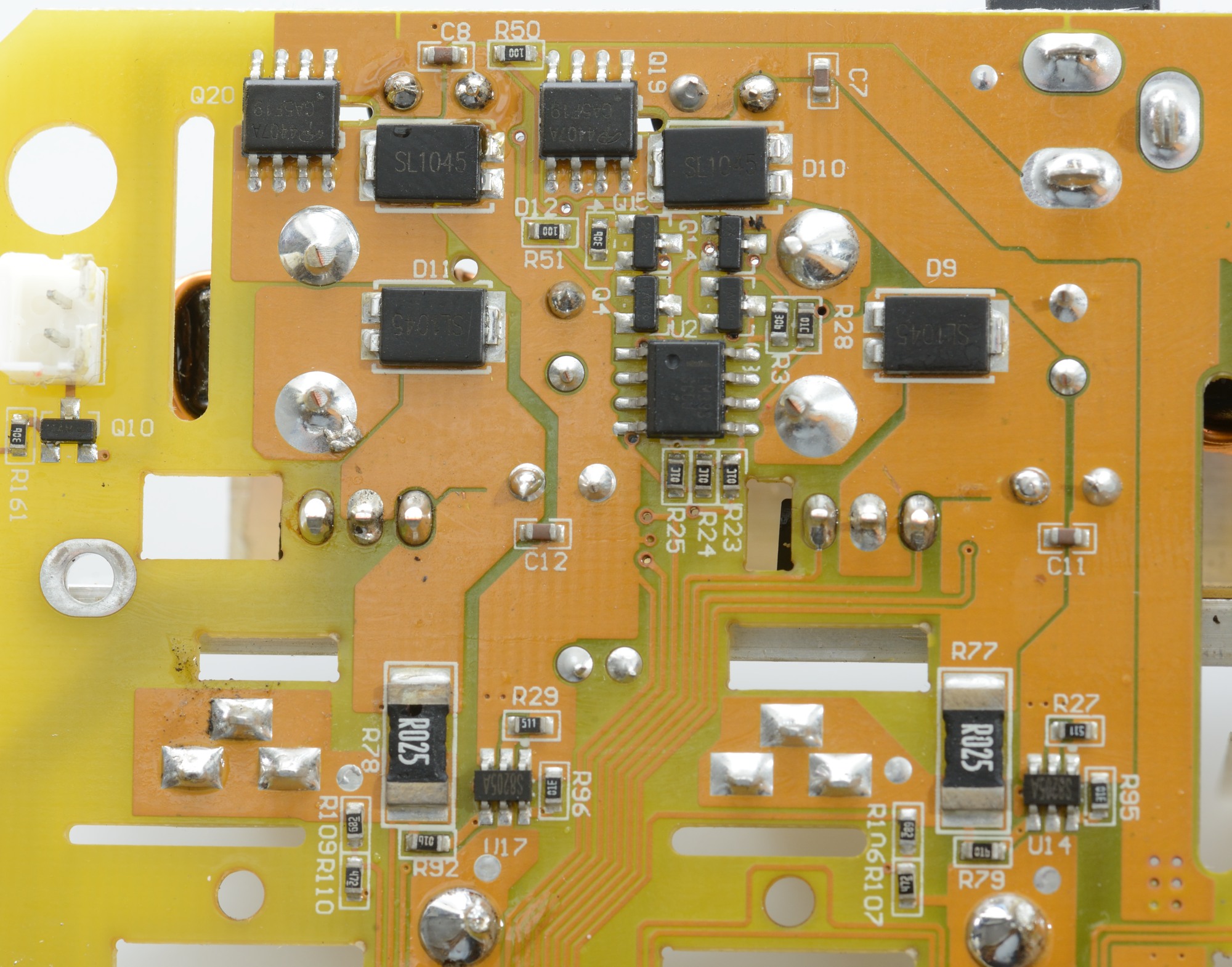
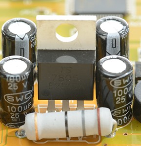
The usb output is supplied from the ACT4070 switcher and has a PTC fuse in series with the output (F5). It looks like the internal power supply is from a 7805 and a AMS1117 (nice with independent supply).
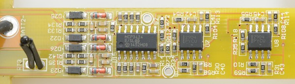
Between the slots is the analog input that measures voltage and current. The ADC is a MCP3424 with 4 differential 18 bit channels, build-in reference and full scale from 0.25V to 2V, each one handles two channels. The 2904 may be dual opams used to amplify the voltages for some ADC.
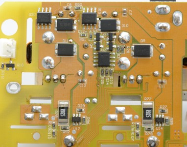
The charging/switcher circuit is mostly diodes and transistors, there is a single LM393. The R025 is probably the resistors that is used for current measurements.
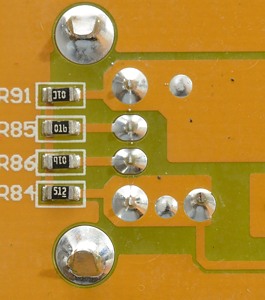
The resistors for the usb output.
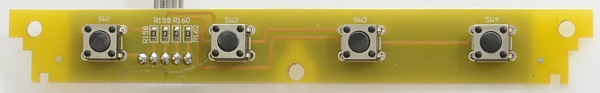
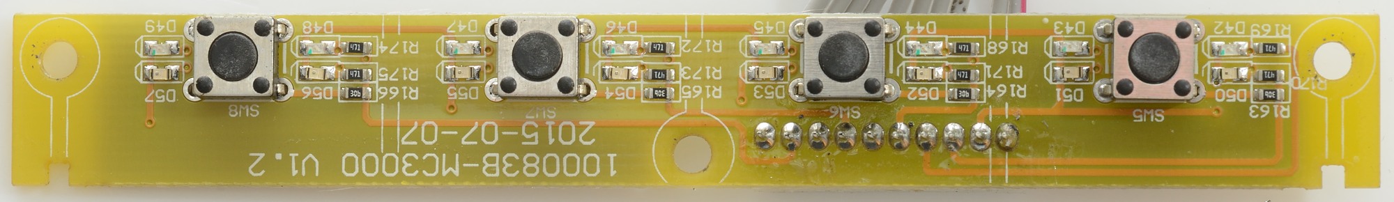
The start/stop and arrow keys uses real switches, that means they can be repaired if they ever break.

The number keys is also switches and there is a red and a green led on each side of the switch.

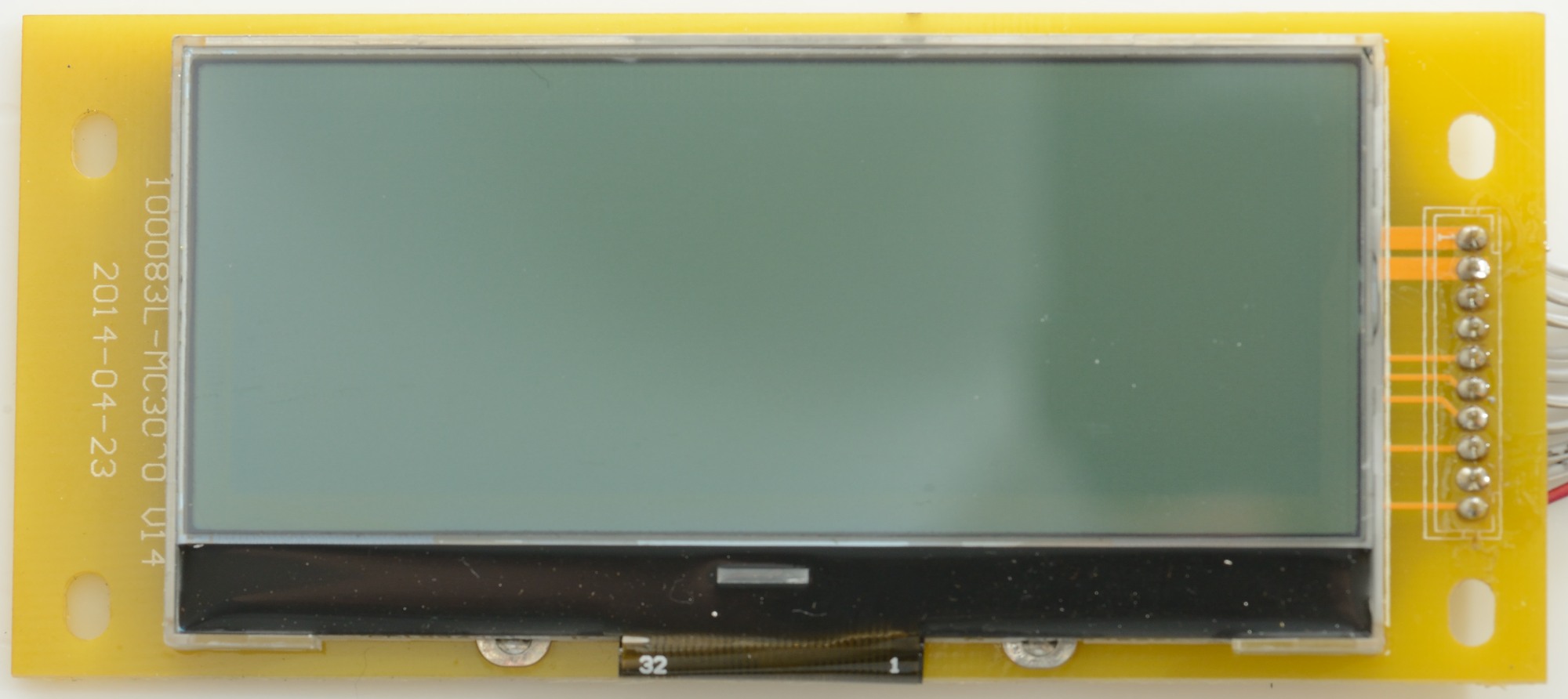
The display is a lcd display.
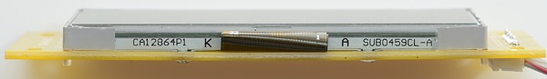
And there is a backlight module below it. There must also be some electronic, but I am not going to remove the display.
Power supply tear down
Because the power supply died, I decided to do a tear down.
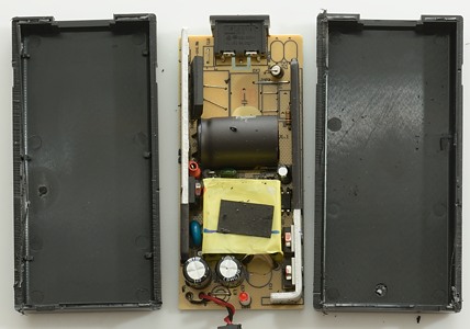
I could not open the power supply with my vice and had to cut it open.
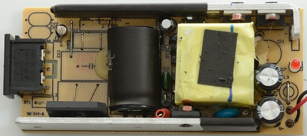
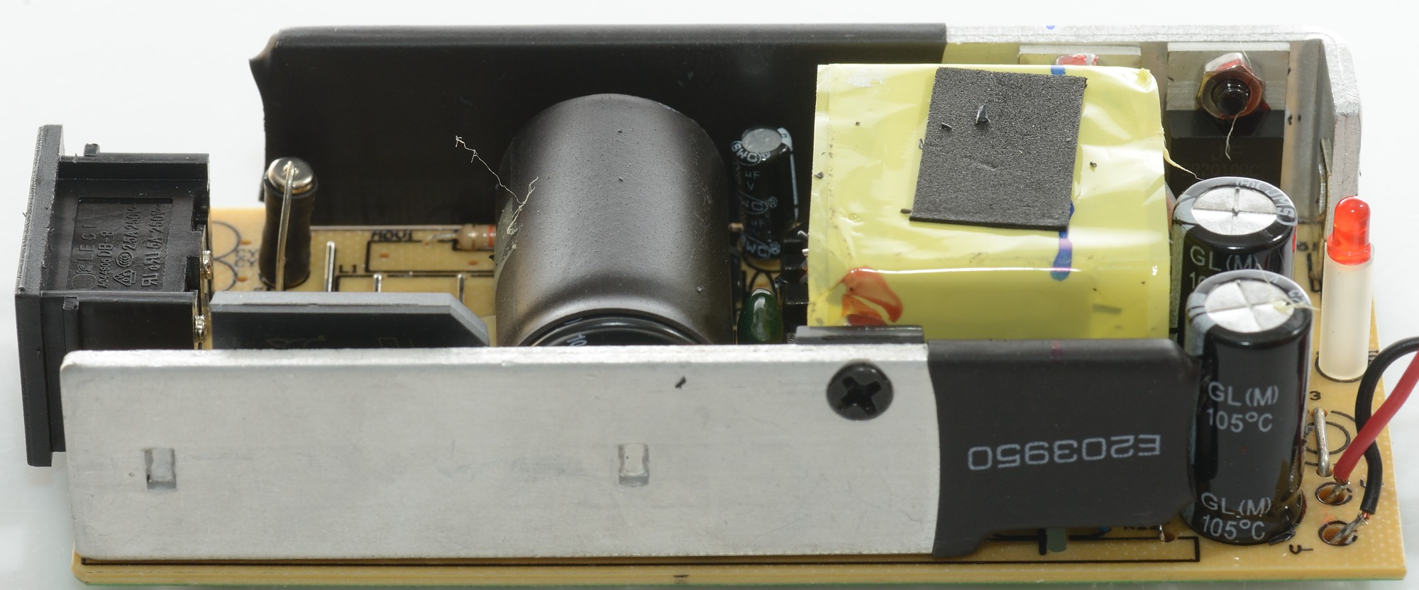
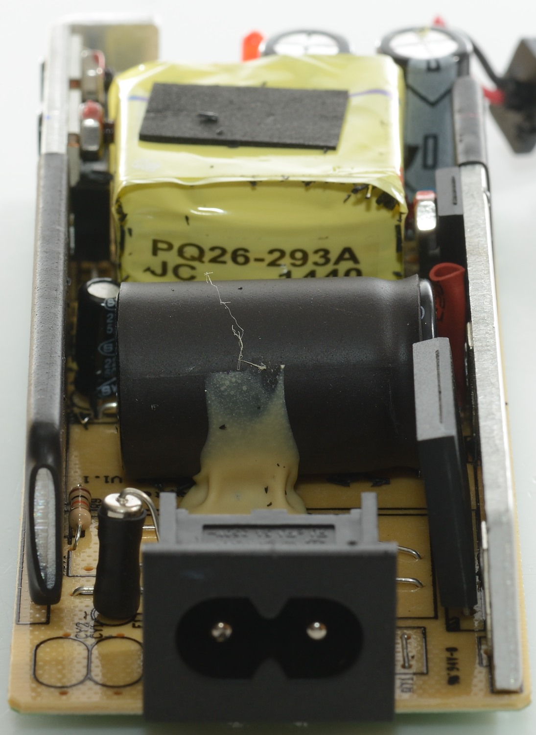
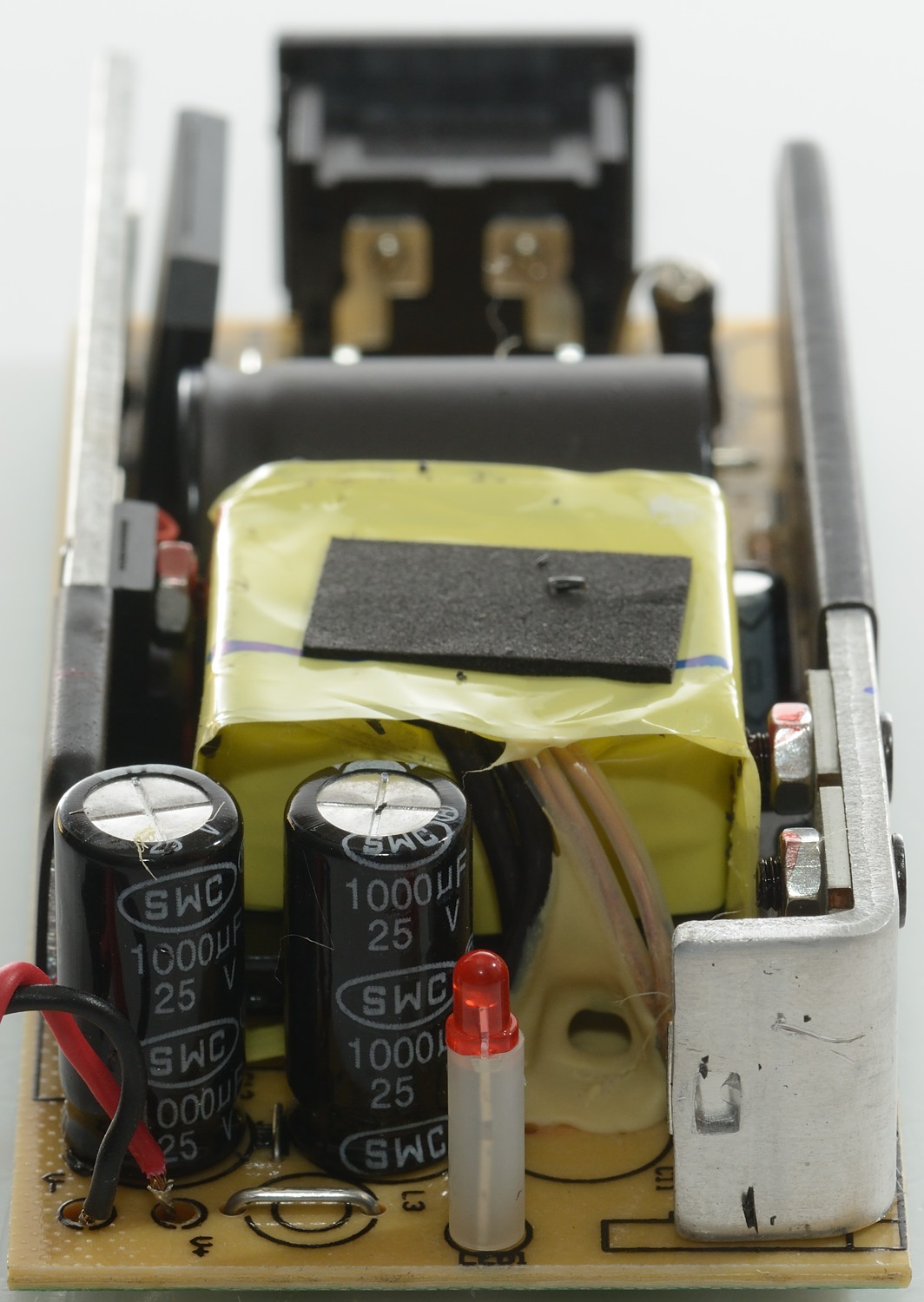
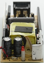
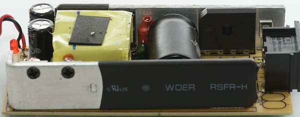
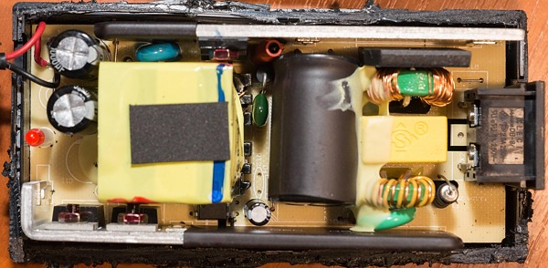
Looking on the top side of the circuit board I can see a fuse, a bridge rectifier, a mains switcher transistor, opto coupler, safety capacitor and two rectifier diodes. Testing the fuse shows that it is blown.
BUT all the noise/EMI protection is missing, this charger will probably not pass a CE or FCC test
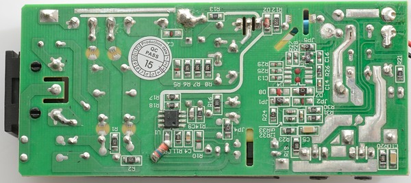
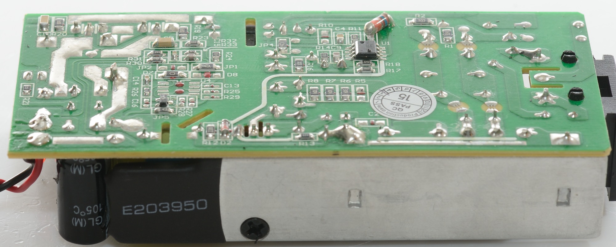
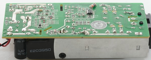
There is not many interesting parts on the bottom, only the mains switcher controller (U1) and a chip to control the voltage feedback (U3). None of the chips has a hole in them.
The circuit board has space for some more parts, probably used for another model.
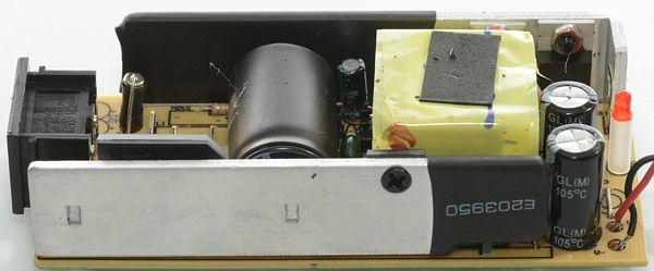
The heatsink has some heatshrink to improve isolation (Required).

The bridge rectifier do not touch the heatsink and I would not expect it needs to. On the output here is a missing inductor (L3).
Again some heatshrink to improve isolation.
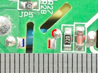
There is no problems with isolation distance, it is very good.
I have seen another tear down of this power supply and some of the inductors and other stuff that is missing here was included. This means that SkyRC probably has two versions of this power supply, one for EU/US and one for countries where they are not that critical with EMI and I got the wrong one for EU, even though the label say CE and FCC approved. These missing parts are not a safety problem.
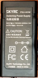
The second picture above is from the teardown below and the label looks the same as the labels on my units.
Here is a picture from the other teardown (cpf user aekvulture), there is four EMI suppression parts just behind the mains inlet.
Short guide for normal use
To select programs for all slots (Same or different do not matter) with or without batteries in the charger:
Press 1, use arrows to select program
Press 2, use arrows to select program
Press 3, use arrows to select program
Press 4, use arrows to select program
Press and hold enter.
To start operating on all slots: Press enter
To start operating on a specific slot: Press and hold number key.
The above do, of course, require that you have already made the programs.
Small programming guide
This guide do not say how to enter or store programs, but it is about what values to use for charging.
As can be seen above I prefer the advanced mode, there is a couple of reasons for that:
1) I do not like all the defaults, they mostly work, but are not ideal.
2) Some default settings will limit the charger.
Remember: C=marked mAh value on the cell.
NiMH
Be careful with charge current, using anything below 0.3C will probably miss termination on AA/AAA cells. I mostly uses around 0.5C.
To keep the cells safe if the terminations is missed use a capacity limit between 130% and 150% of the cells capacity and a timer cutoff calculated as capacity/current*1.4, i.e. for a 2000mA cell at 1A it is 2000/1000*1.4 -> 2.8 hours -> 2 hours 48 minutes.
FOr NiMH the -dv/dt setting must be as low as possible, I used 3mV for my test, but a lower value might be even better. Too low value will not damage the cell, but might give early termination.
LSD cells do not need any trickle charge, for other cells a 10mA trickle charge can be used, but it not really needed either (Some manufactures recommend a time limited trickle charge after a -dv/dt charge).
Official termination voltage for NiMH when discharging to measure capacity is 1 volt, but there is no problem going lower (like 0.8 volt).
With NiMH the cycle mode can be used to refresh cells that has been unused for some times.
break_in is the official way to measure capacity, but this will first work when the charger software is fixed.
LiIon
LiIon cannot really be over charged when the charger uses the correct voltage, but damage cells can do nasty things if the charger continues to charge them. Using the capacity and timer cut specification will reduce the risk of that.
Because LiIon do only need rated capacity when charged the safety limit can be place as low as 10% above the rating, but more is also acceptable. For 18650 I will be using 3600mAh and for 26650 7000mAh limits.
Time can be estimated as capacity/current+2 hours, i.e. for a 3400mAh cell at 1A it is 3400/1000+2 -> 5.4 hours or 5 hours and 24 minute. The extra hours added will depend on cell age and termination current, two hours will work in most cases.
When discharging using 3V as "cut volt" is always safe, for lower voltage it is best to check the datasheet, but a single discharge to a lower voltage without using the "D.REDUCE" option will probably be safe (I have never seen any problems in my tests).
Testing the mains transformer with 2500 volt and 5000 volt between mains and low volt side, did not show any safety problems.
Conclusion
This charger can handle many chemistries and many battery sizes and in addition to this it has a good precision, all of this is way above any other (consumer) charger on the market at the current time.
Using the safety functions (Capacity, time, temperature) it is very easy to add a extra layer of safety to the charge process and due to the programs it only has to be configured once and then it will be active for all charging of the battery type.
The charger has 3 UI modes, the dummy mode is mostly for people that got this charger without realizing what it is, the simple mode can be used to charge/test any chemistry, but it is not really possible to adjust any parameters. For really using the charger there is only advanced mode (Or PC/phone interface).
The charger is not without issues, most of them will probably be fixed with software upgrades, I have collected some of them here:
- It is required to remember the program numbers or press a key, on the initial screen there is no hint on how the selected program works.
- Default time on LiIon is 3 hours, this is to short.
- When terminating on time or capacity, no capacity information is saved.
- Break_in shows charged capacity, not discharge capacity.
- Backlight always requires a keypress to turn on, putting a battery into the charger will not turn the light on
- Factory calibration do not match specifications.
- The PC software requires a high screen resolution
- NiMH charge curves looks messy on PC, an option to hiding measuring pauses would be nice.
- PC software saves csv files at wrong location.
- It is not possible to copy programming from one charger to another, people with more than one charger (That will be me) must enter each program on each charger!
- The Bluetooth software is not stable and do not work on all phones.
- Strange coding on the usb output, why not use a chip to automatic get the best coding?
Even with all the above issues I can only call it a very good charger, but it is not for everyone.
Notes
The charger was supplied by Gearbest for a review.
The supplied power supply died during one of my first test and for the rest of the testing I used my own power supply. I assumed that it was faulty power supply and have not included that in my evaluation of the charger. The 5000V test was done on the two power supplies supplied with the production chargers, they do work fine.
Here is an explanation on how I did the above charge curves: How do I test a charger
Read more about how I test USB power supplies and chargers