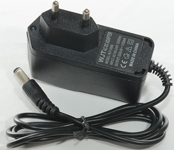
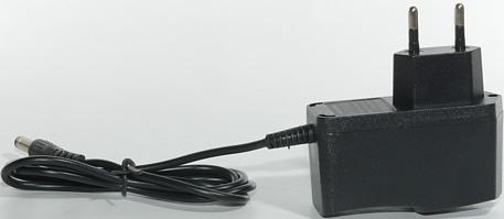
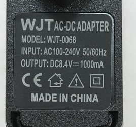
2S 1A LiIon charger WJT-0068
Official specifications:
- Input: 100-240VAC 50/60Hz
- Output: 8.4V 1000mA DC
- LED indication for Power On / Charging / Full charge
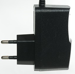
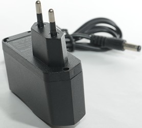
- Style: EU Plug
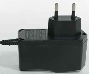
Color: Black
This charger is for battery packs with 2S1P (2 in series 1 in parallel), 2S2P or more parallel LiIon cells. The battery pack is supposed to contains its own protection and balancing.
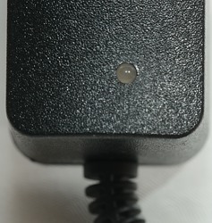
The led is a two color led, it will show red when charging and green at all other times when the charger is powered.
Measurements
- Connector is 5.5mm/2.1mm
- Green led is on when power connected, but no battery.
- Green led is on when battery is connected, but no power.
- Green led is on when power and battery is connected and battery is full.
- Red led is on when charging.
- When overloaded/shorted the led will flash red.
- It will start regular charging at 3.6 volt
- Unloaded voltage is 8.47
- Unloaded power consumption is 0.24 watt
- Change from charging to done is a slow process, it takes more than 30 minutes to change from red to green.
- The charger will drain the batteries with 7.5mA when not connected to power.
Testing with 4 cells means a 2S2P pack.
.png)
The charge curve is a CC/CV, but the charger never stops, it just reports battery full (Green led) and continues to charge.
%20Efficiency.png)
Same curve as above, I have just replaced capacity with efficiency, it is at about 70% during charge.
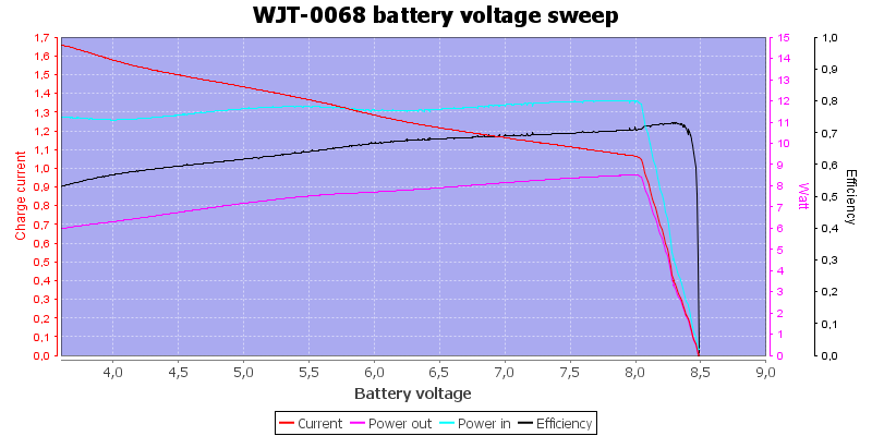
In the above curve I simulated a battery voltage from over discharge to fully charged. The charger current depends on the battery voltage, but there is no real slow charging when the pack is over discharged.
During a charge I took IR photos at regular intervals of the hottest part of the charger:
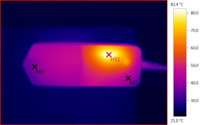
M1: 43,3°C, M2: 37,9°C, HS1: 82,4°C
HS1 is the rectifier diode, the small diode get rather hot.
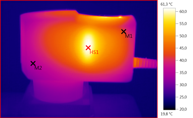
M1: 41,9°C, M2: 34,8°C, HS1: 61,3°C
HS1 is the mains transformer.
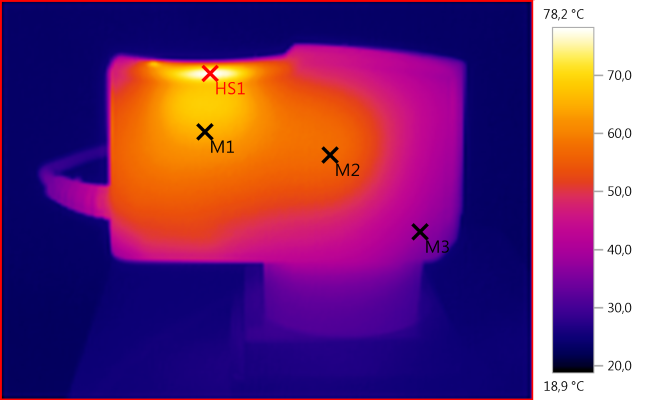
M1: 65,5°C, M2: 57,2°C, M3: 38,0°C, HS1: 78,2°C
Again HS1 is the rectifer diode.
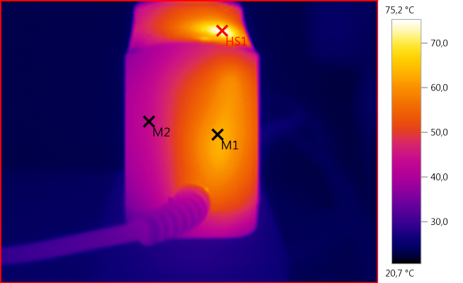
M1: 62,8°C, M2: 43,6°C, HS1: 75,2°C
M1 is the large resistor to measure current.
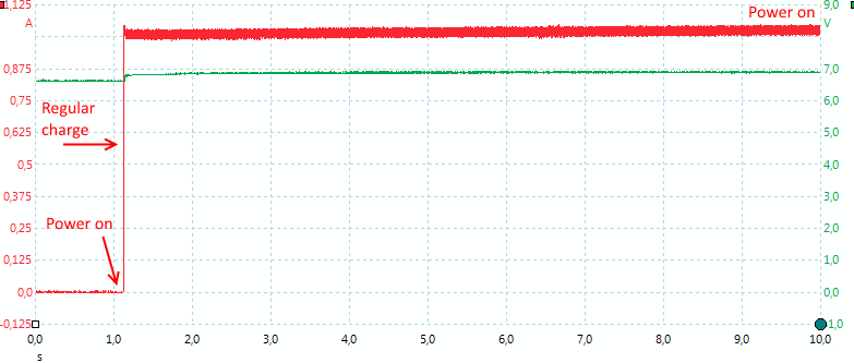
The charger starts fast and charges with a steady current.
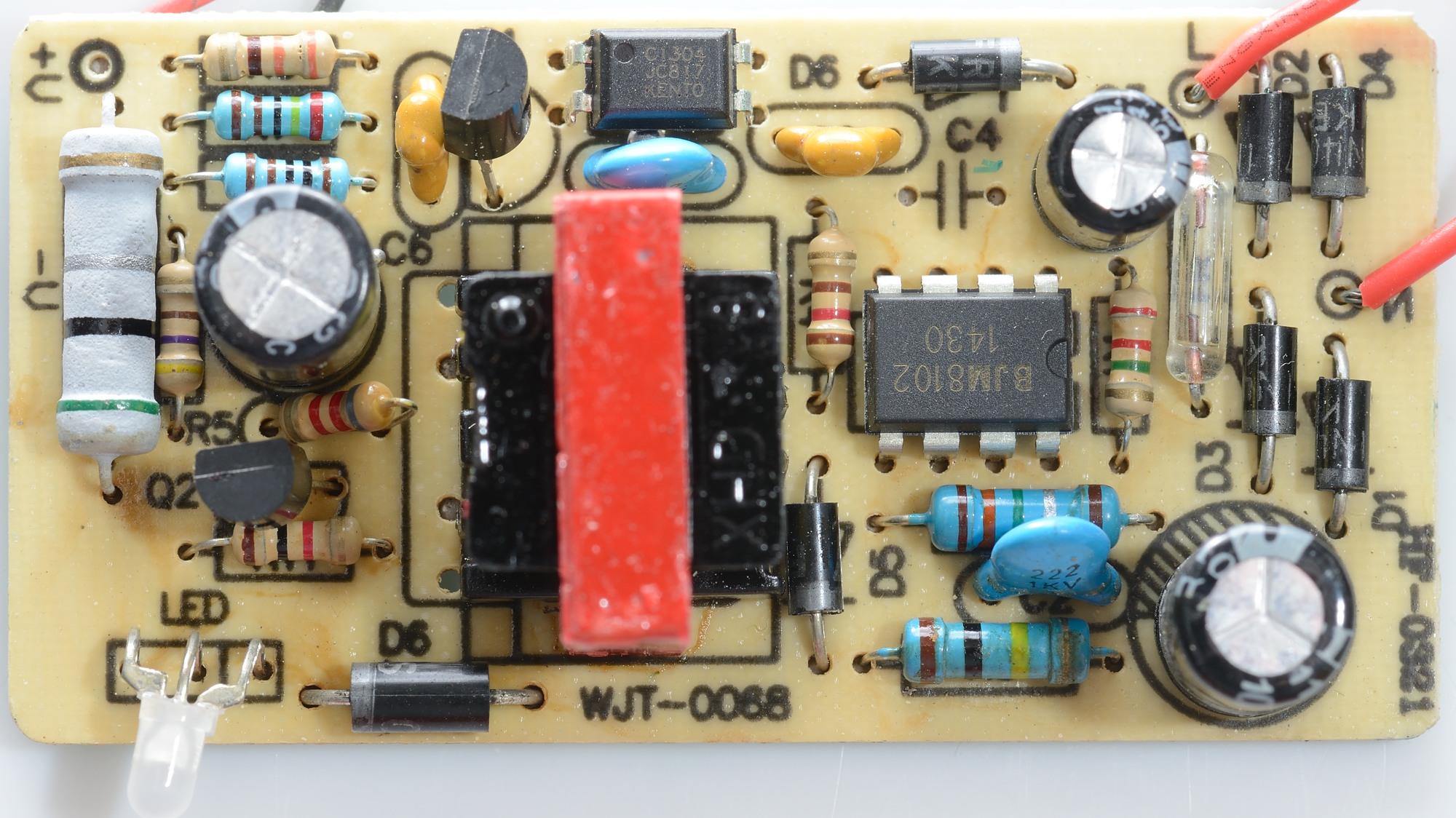
Tear down
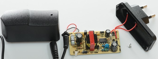
This charger had one screw.

Input has a fuse, then a bridge rectifier (4 diodes), a mains switcher IC.
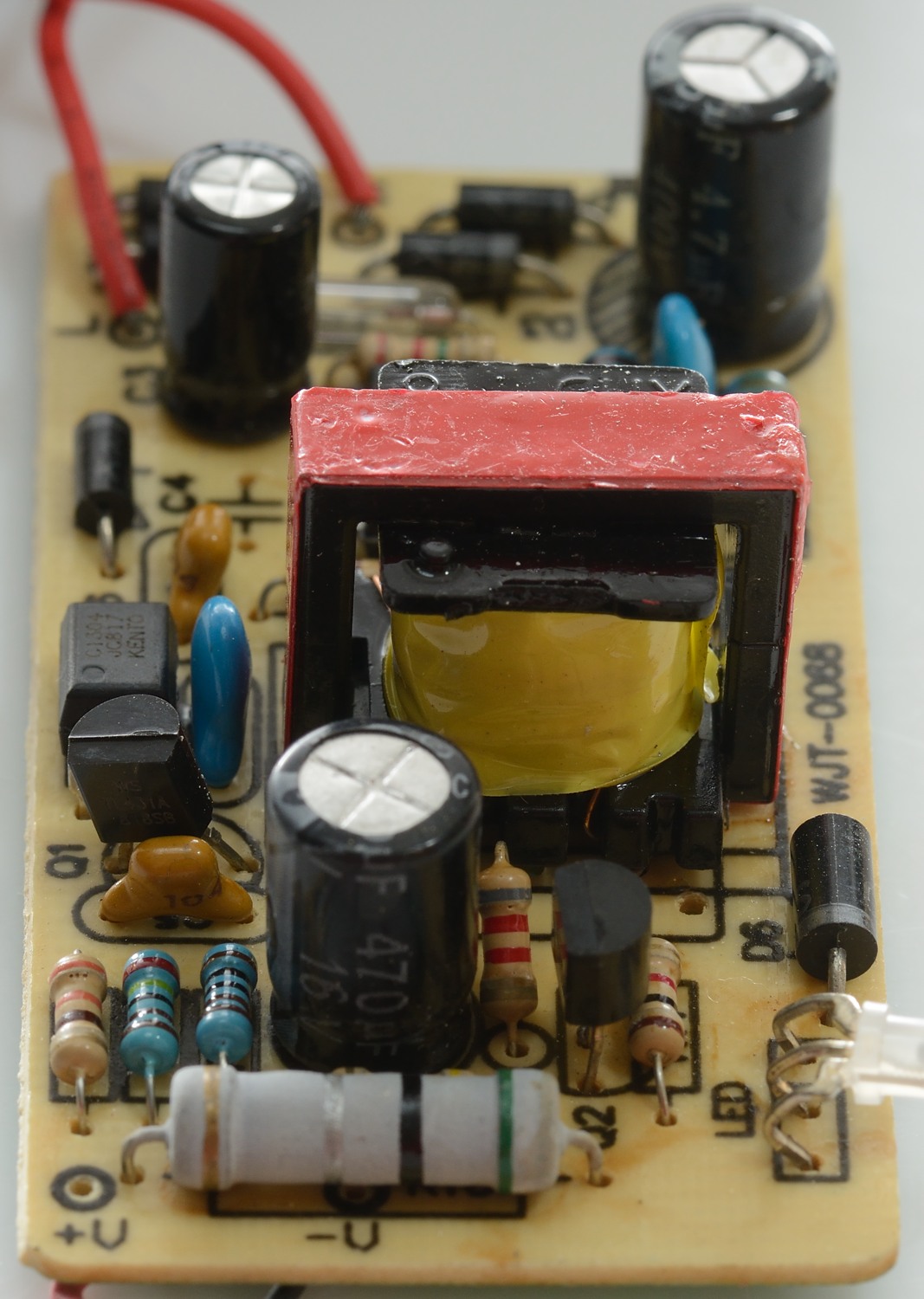
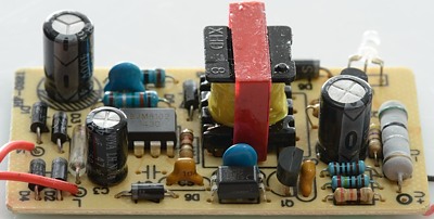
On the low volt side is electronic to detect current (But not an IC), the current is measured over the big resistor. There is optical feedback. Being only 1A the rectifier diode is rather small (D6), as can be seen above it gets hot.
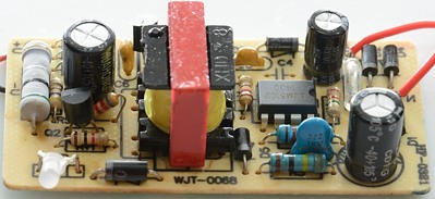
Look at the blue capacitor on this picture, it is not a safety capacitor, but rated for 1kV, this might be acceptable here, but same type of capacitor is used between mains and low volt side (very bad).

The current measuring resistor is easy to see here, same is the input bridge.
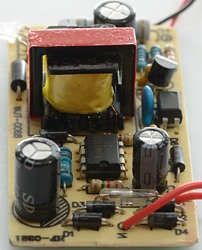
Here the opto feedback and the blue non-safety capacitor can be seen. I believe that this capacitor is the reason for the short between mains and low volt side.

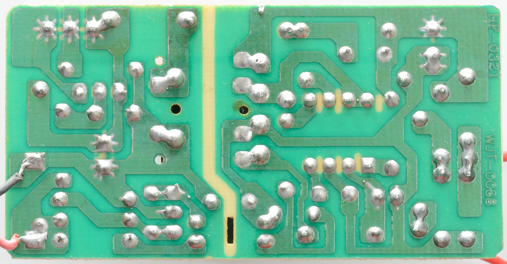
There is no parts on the bottom, this is a cheap charger.
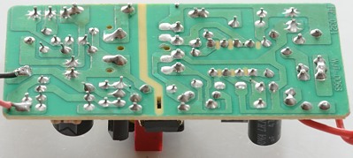
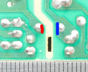
Interesting to see the lack of safety. Slots in the circuit board are used where tracks are close, here they have not placed the slot where the tracks are closest.
The actual distance between mains and low volt side must be over 6mm on circuit board, here it is 3mm.
The charger passed a isolation test with 2500 volt, but failed a test with 5000 volt, this makes it doubtful to use with 230VAC mains. The fail made a short between mains and low voltage side (Very bad)!
Conclusion
Performance is acceptable, but safety is not. One spike on the mains side and the low volt side is directly connected to mains.
Stay away from this!
Notes
The charger is from Ebay dealer 800tuan, I got it with the help of BLF/MTBR user Ledoman.
Here is an explanation on how I did the above charge curves: How do I test a charger