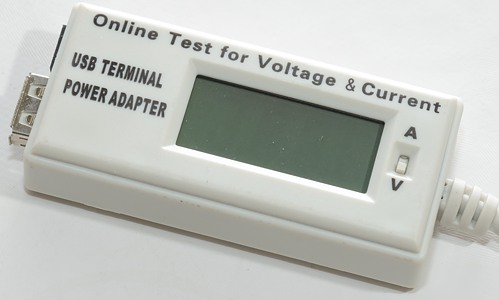
USB meter: Online Test
Official specifications:
- Cable Length: 16cm/6.3"
- Body Size: 7.5 x 3.5 x 1.8cm/3" x 1.4" x 0.7"(L*W*T)
- Main Color: White, Black
- Materials: Plastic, Metal
- Net Weight: 61g
I found this unit on Ebay at a dealer called sellerbible.
How does it look
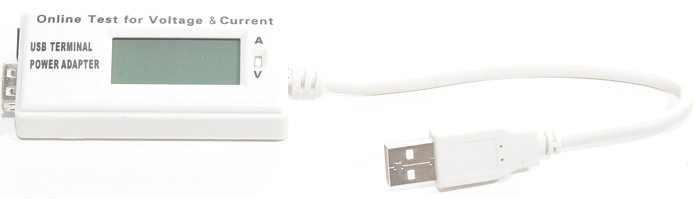
This usb meter has a cable on the usb input.
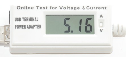
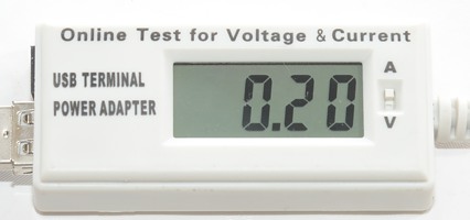
A switch is used to select between voltage and current display.
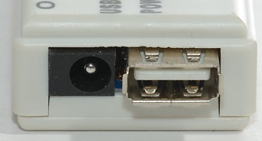
In addition to the usb output, there is also a DC barrel connector for 5 volt input.
There is no markings on the device showing the DC connector is for 5 volt input.

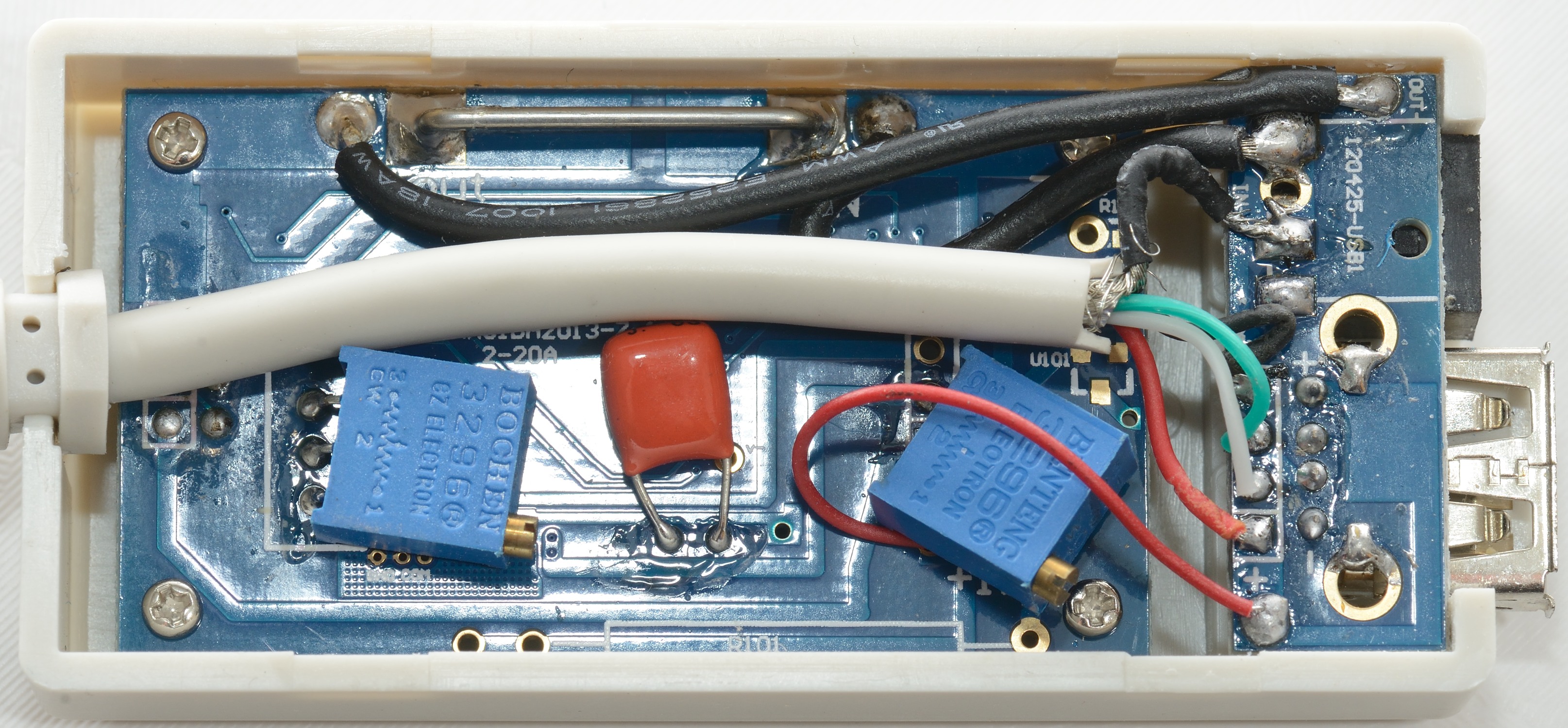
There is no screws, I could just pry the bottom off. I was a bit surprised about the inside with two circuit boards and lots of wires.
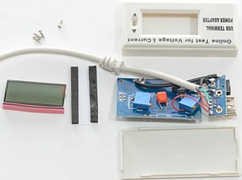
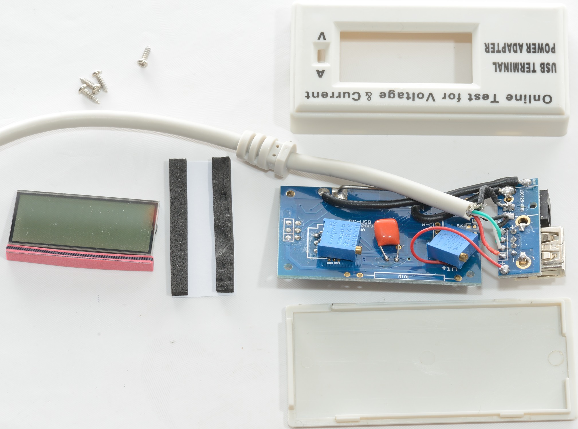
Four screws later and the circuit board is out together with the display.
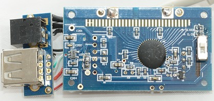
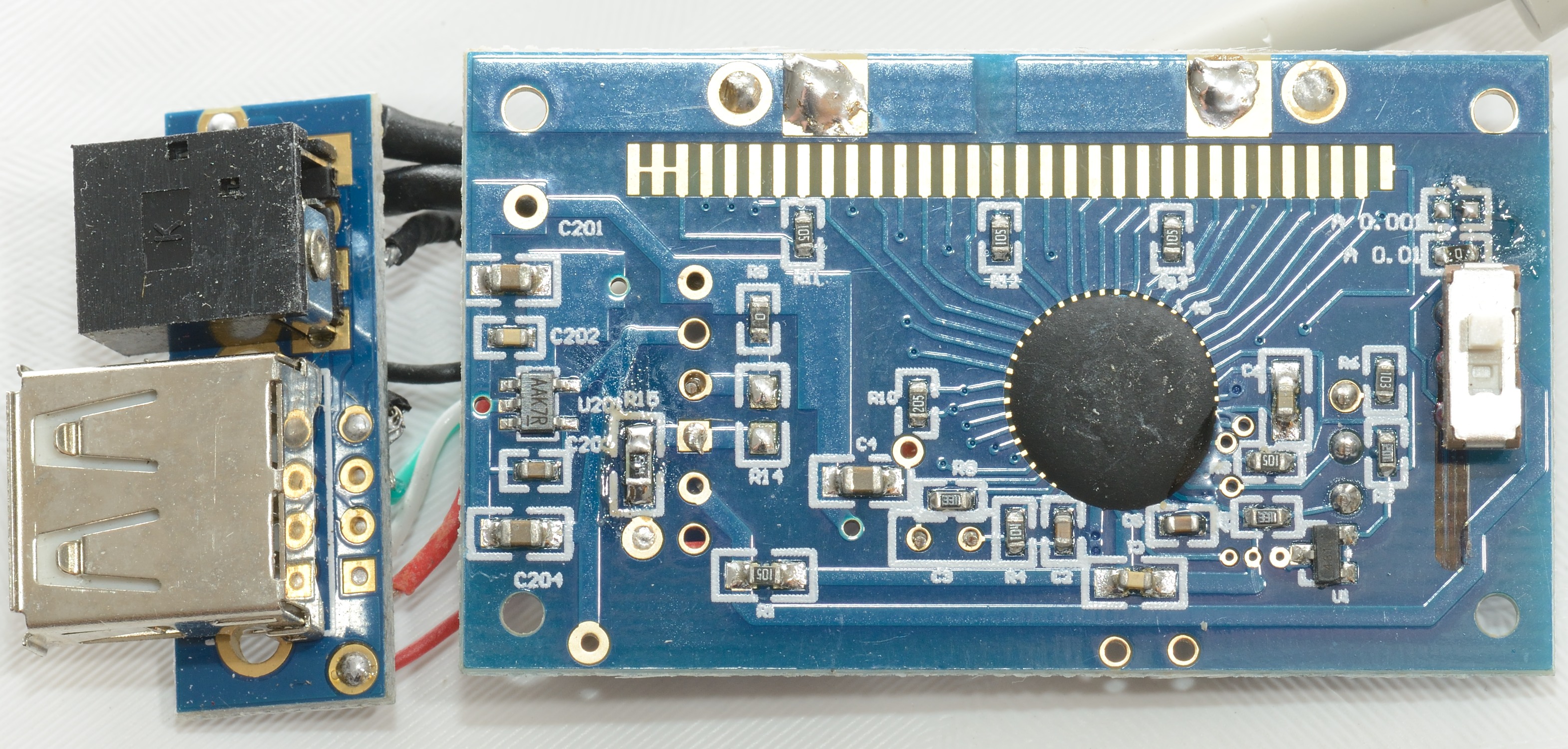
It looks like this device can be made in two version with different current resolution.
The black blob is the microprocessor, the raw chip is mounted directly on the circuit board.
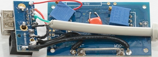
The current sense resistor is a piece of wire.
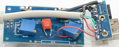
Two quality trimpots to adjust current and voltage readings.
Measurements
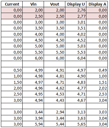
- The meter uses 1.1mA current
- The display shows a voltage midway between input and output.
- The current is within 0.05A (The reading gets slightly higher when the usb meter is warm).
- Internal resistance is about 0.17ohm including connection resistance.
- USB data works fine.
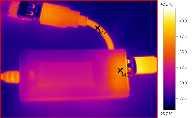
M1:36,8°C, M2:36,4°C, HS1: 42,1°C
Notice that the cable is warm, i.e. the resistance in the cable will loose some power.
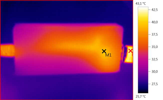
M1: 39,4°C, HS1: 43,1°C
Conclusion
This usb meter works fairly well, but I would have liked some markings for the DC connector.
A acceptable device for people that want a manual V/A switch.
Notes
How do I make the test