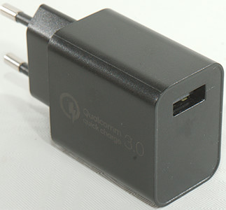
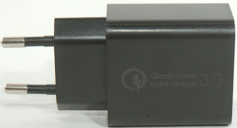
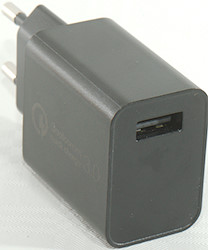
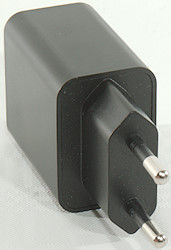
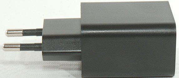
Xtar 18W Wall Adapter DBS15Q
Official specifications:
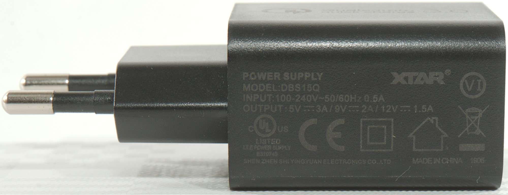
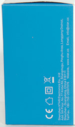
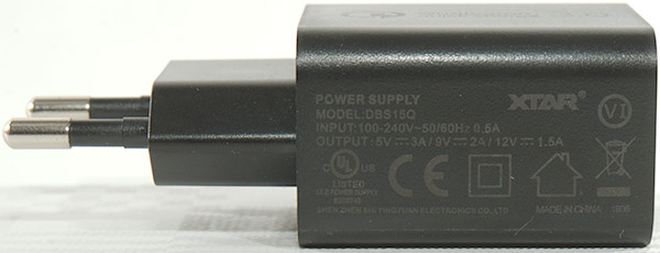
- Model: DBS15Q
- Input: 100-240VAC 50/60Hz
- Output: 5V 3A, 9V 2A, 12V 1.5A
I got this charger from Xtar together with the PB2S battery charger and power bank.
It was in a cardboard box without any accessories.
Measurements
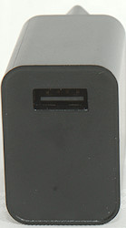
- USB output is coded as Apple 2.4A, DCP, QC3, Samsung-AFC, Huawei-FCP
- Minimum QC3 voltage is 3.7V
- Power consumption when idle is 0.05 Watt
- USB outputs are in parallel
- Weight: g
- Size: mm
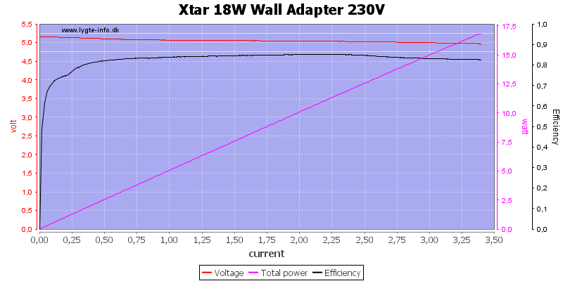
Output on 5V is about 3.3A
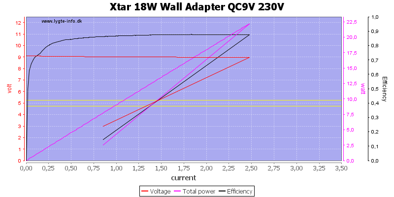
On 9V it is 2.5A
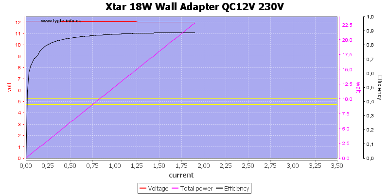
And on 12V it is 1.8A, all matches the specifications very nicely.
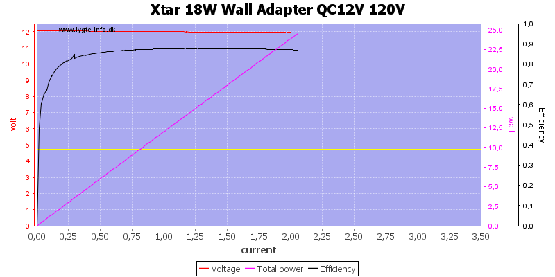
With 120VAC the 12V output is slightly higher at 2A.
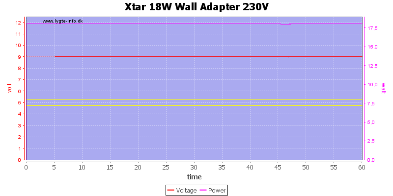
For a load test I used 9V 2A load for one hour, it worked fine.
The temperature photos below are taken between 30 minutes and 60 minutes into the one hour test.
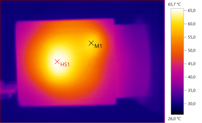
M1: 60.6°C, HS1: 65.7°C
HS1 is the mains transformer.
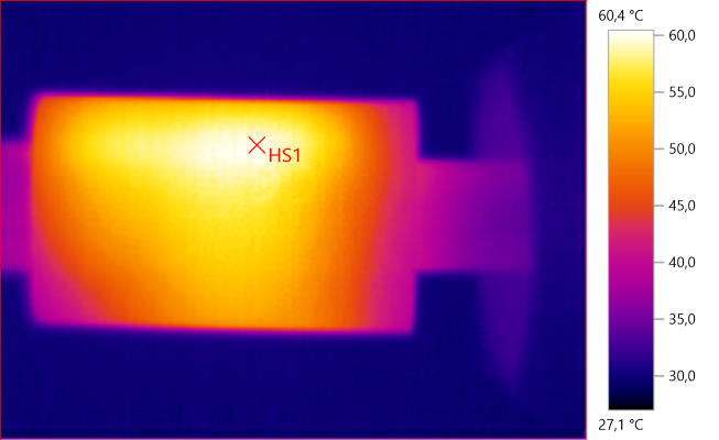
HS1: 60.4°C
HS1 is the mains switcher transistor and circuit board.
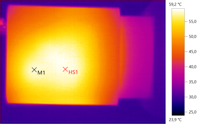
M1: 58.2°C, HS1: 59.2°C
HS1 is the mains transformer, M1 is probably the rectifier.
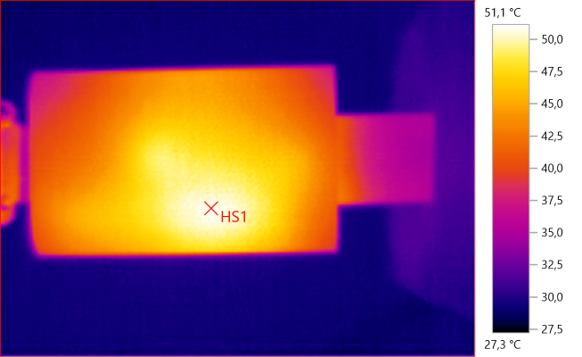
HS1: 51.1°C
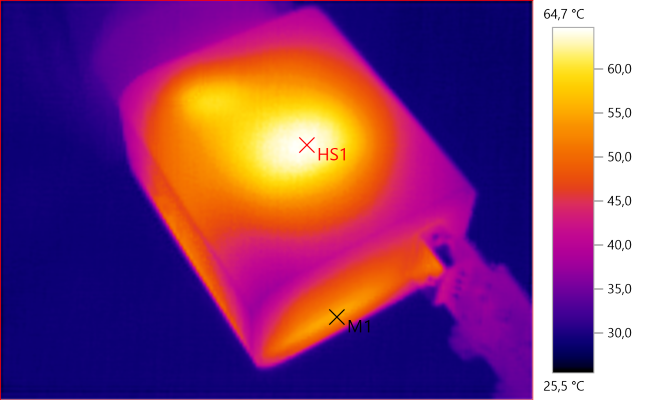
M1: 55.1°C, HS1: 64.7°C
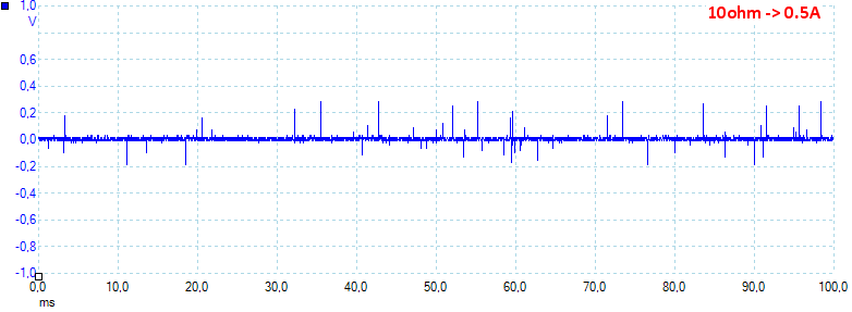
At 0.5A the noise is 13mV rms and 259mVpp.
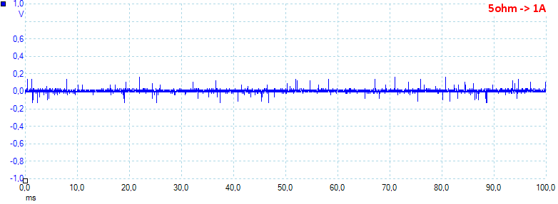
At 1A the noise is 17mV rms and 441mVpp.
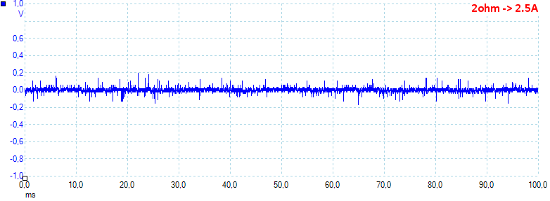
At 2.5A the noise is 84mV rms and 732mVpp.
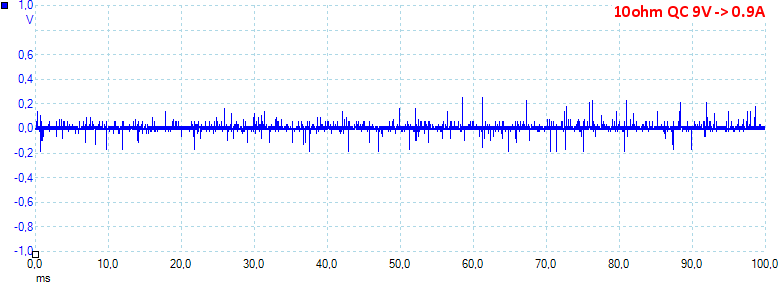
At 9V 0.9A the noise is 18mV rms and 322mVpp.
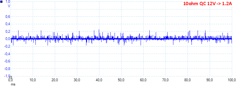
At 12V 1.2A the noise is 25mV rms and 348mVpp.
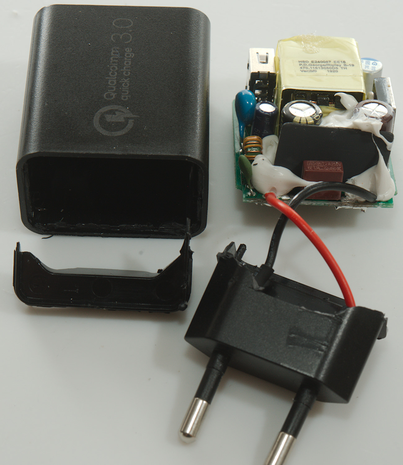
Tear down
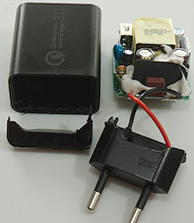
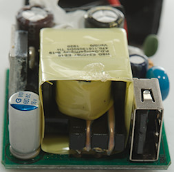
I used my usual method of mounting the bottom in my vice and whacking the top with a mallet, the charger did open, but the bottom broke.
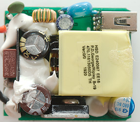
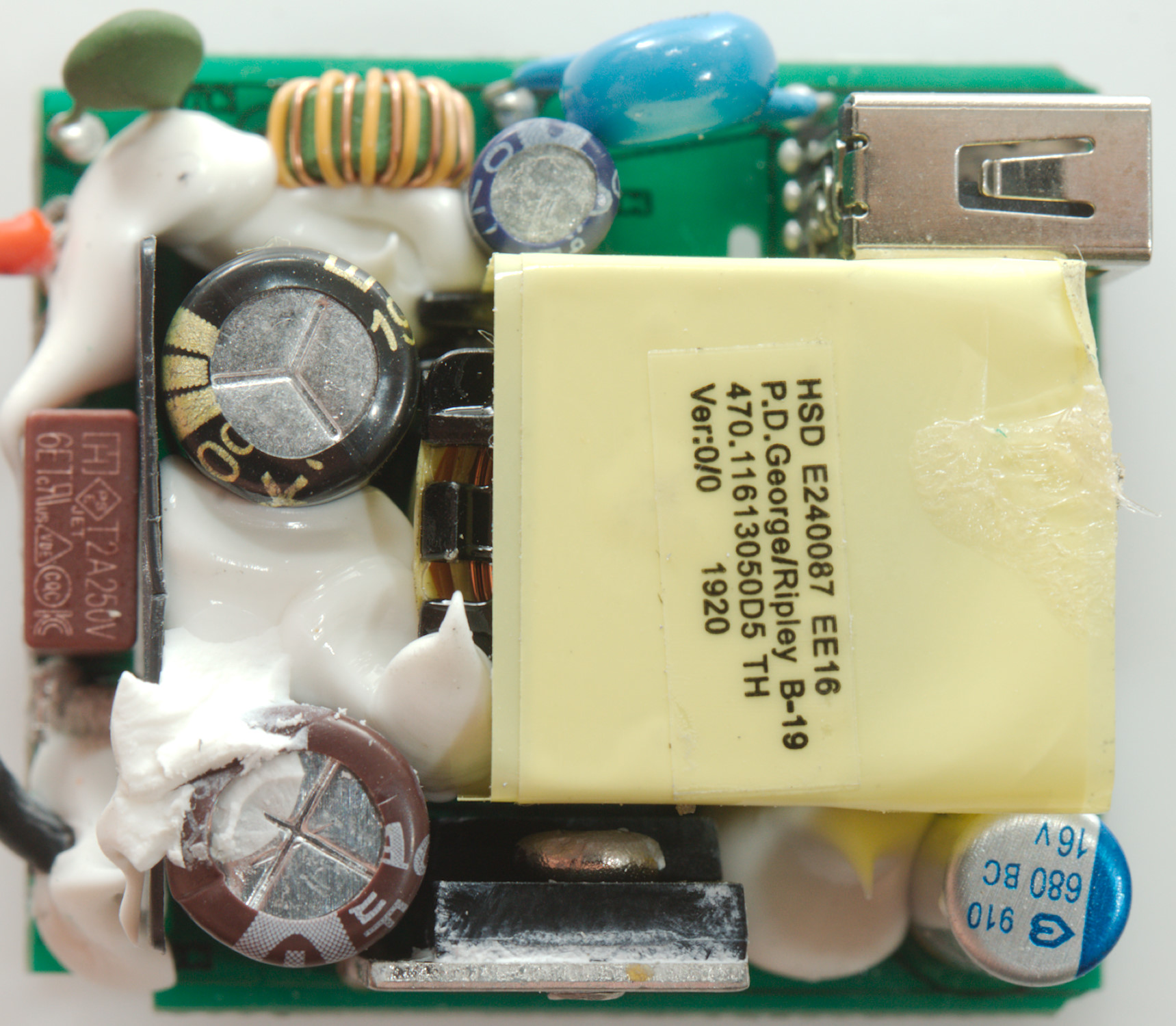
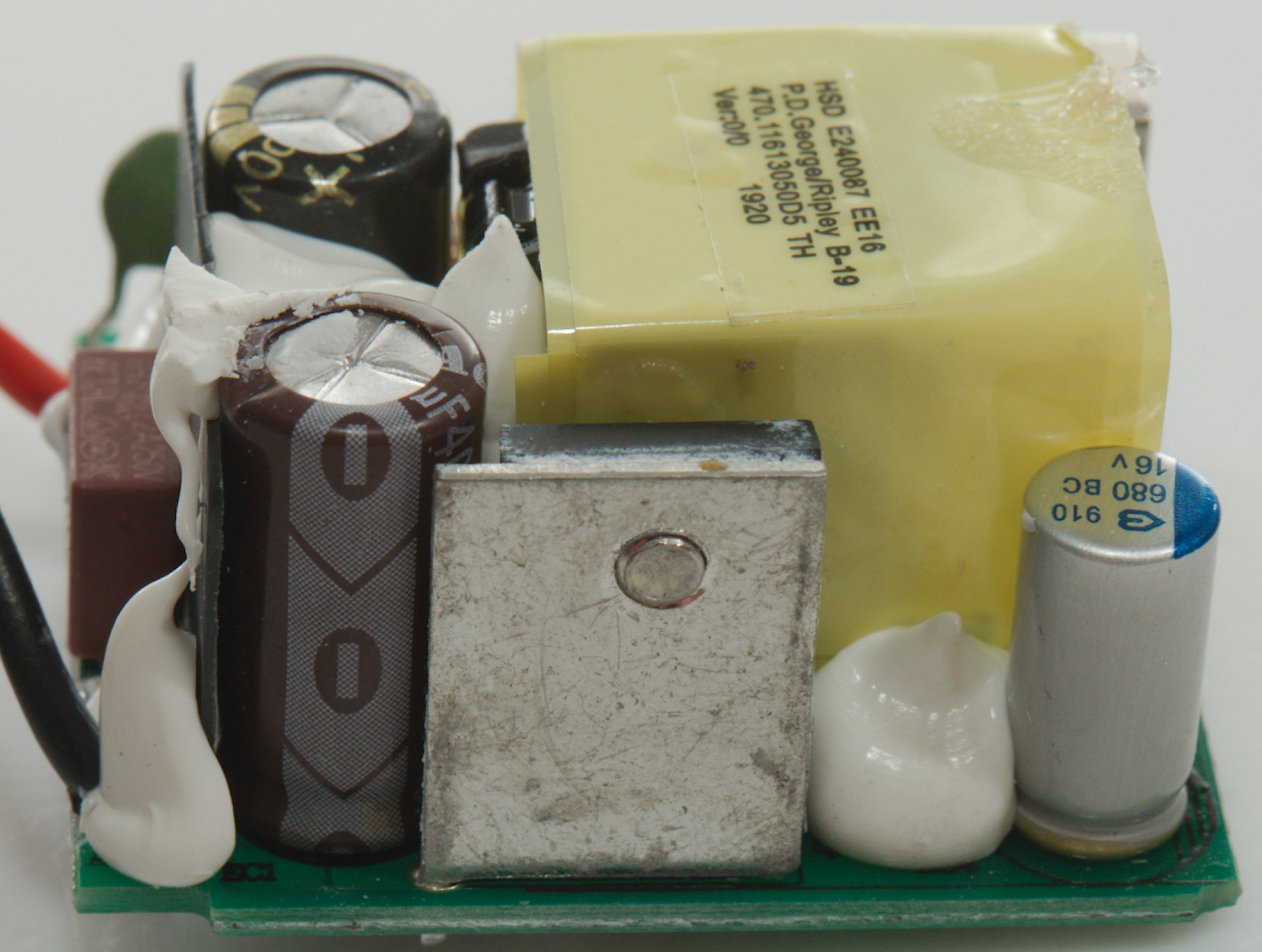
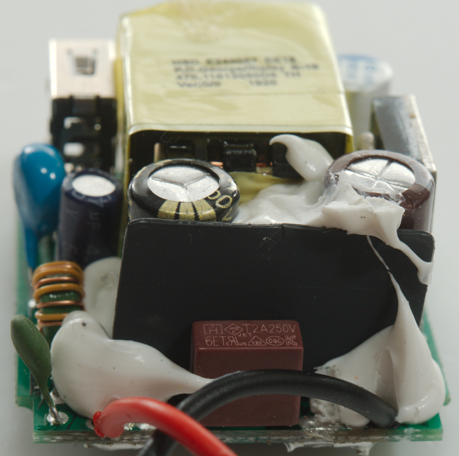
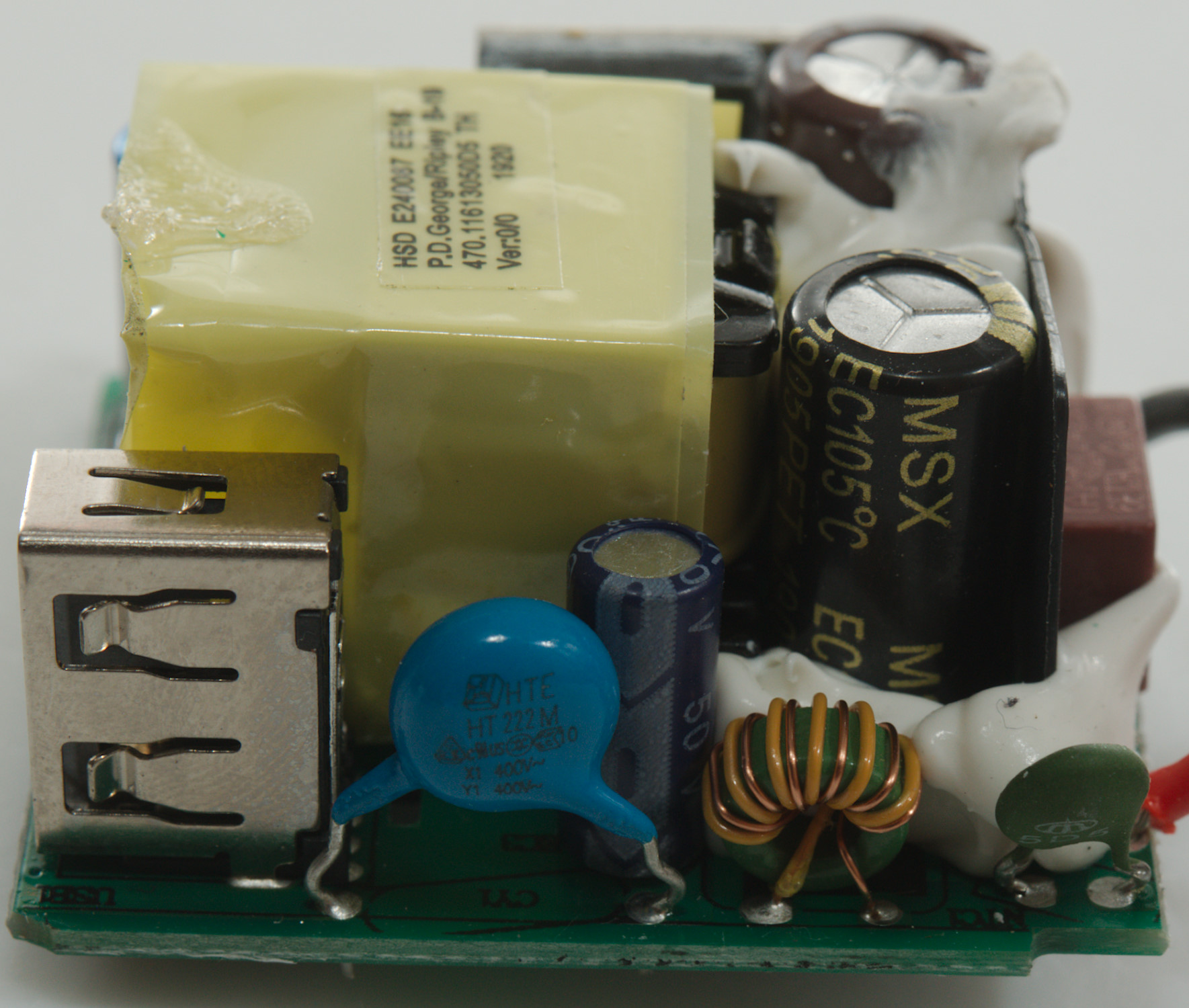
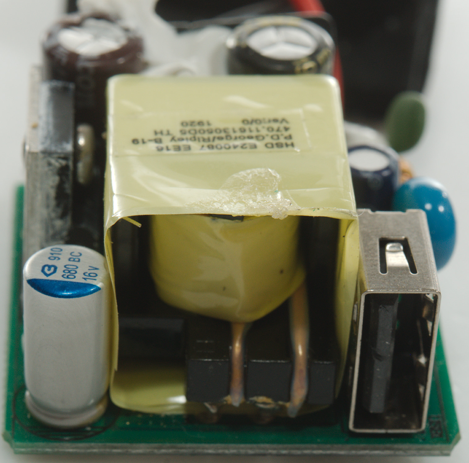
On this side of the circuit board is a input fuse, a inrush current limiter (NTC1), a common mode coil. The mains switcher transistor is on small heatsink. Between mains and output is the usually safety capacitor (CY1).
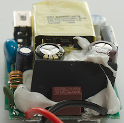
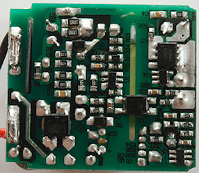
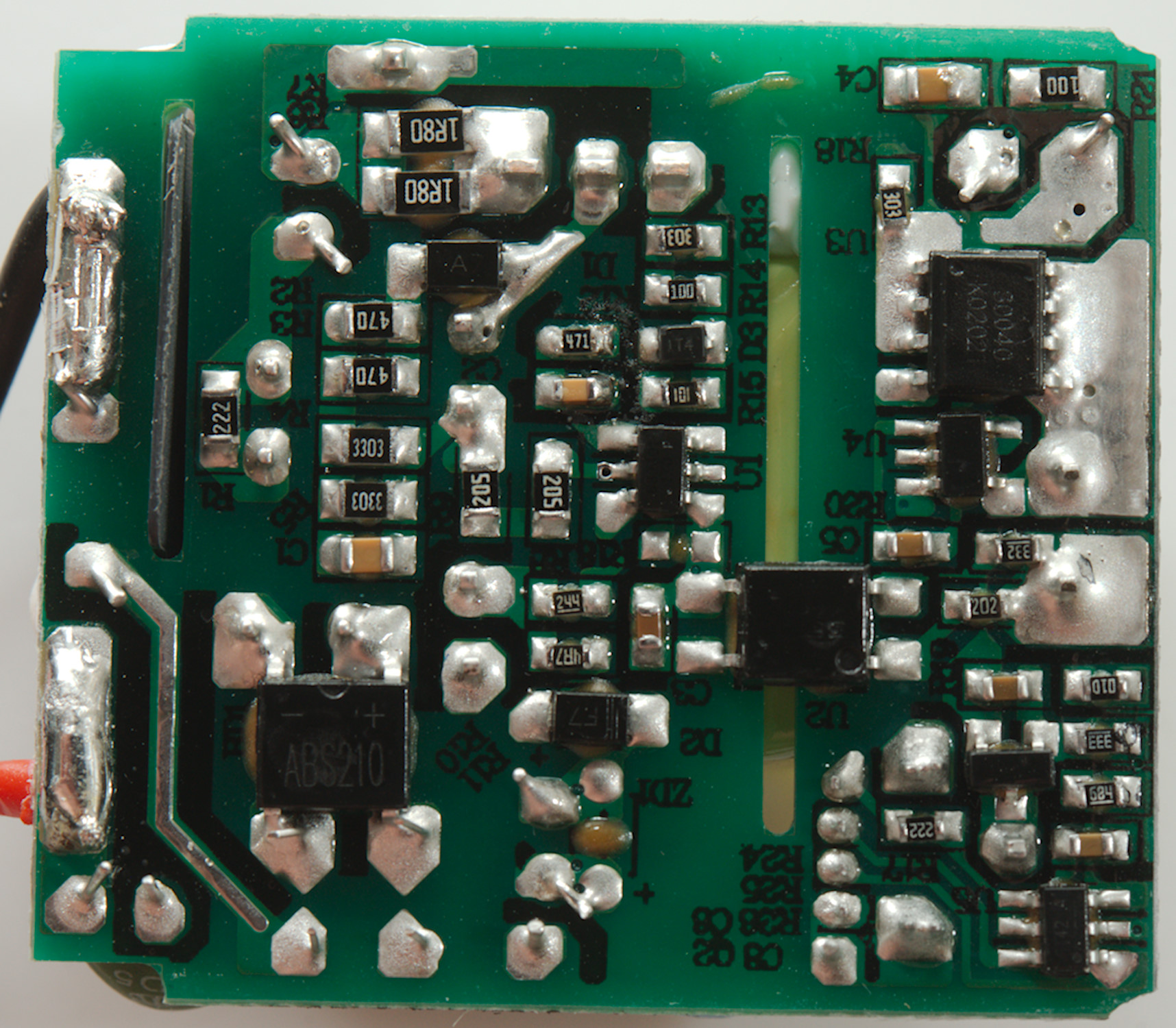
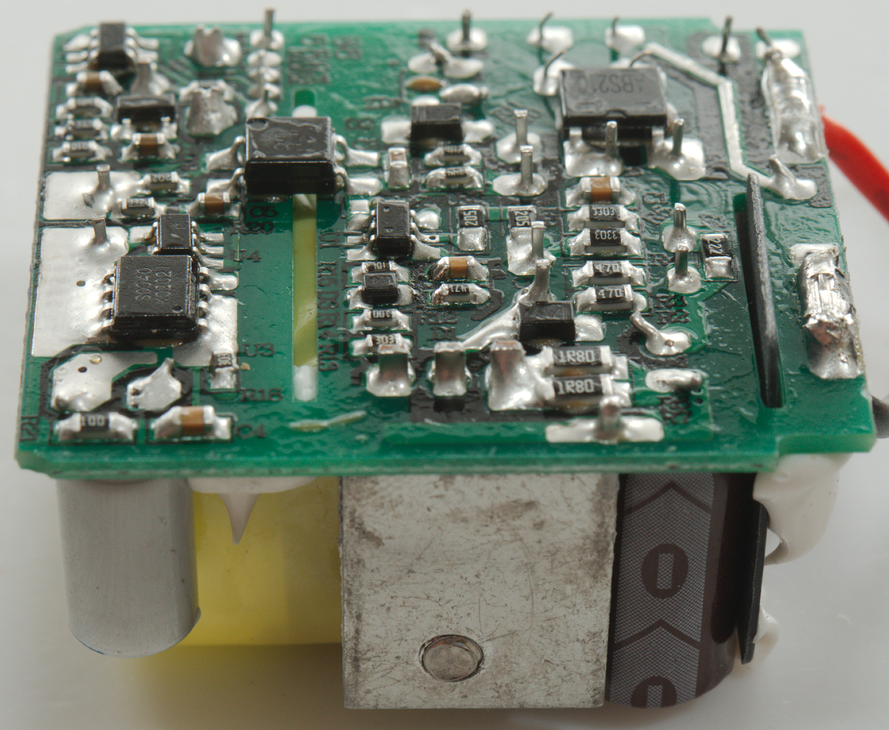
On this side is the mains bridge rectifier (BD1) and the mains switcher controller (U1), there is opto feed back (U2) from the low volt side.
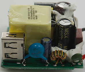
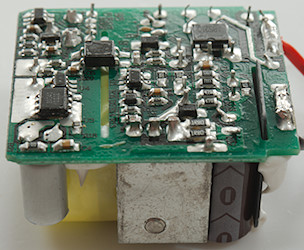
The low volt side is a synchronous rectifier transistor (U3: Marked 30040/K0202) and controller (U4). The USB output is controlled from a QC controller (Q5: FT42?A) and a 3pin device, probably a 431 reference.
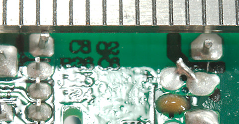
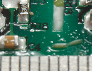
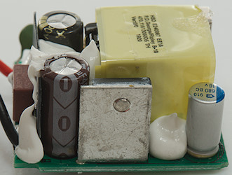
It looks like the distance between low volt and mains is around 6mm.
Testing with 2830 volt and 4242 volt between mains and low volt side, did not show any safety problems.
Conclusion
This is a QC3 charger with support for a few extra codings.
It is a good charger.
Notes
The charger was supplied by Xtar for review.
Review of PB2S
Index of all tested USB power supplies/chargers
Read more about how I test USB power supplies/charger
How does a usb charger work?