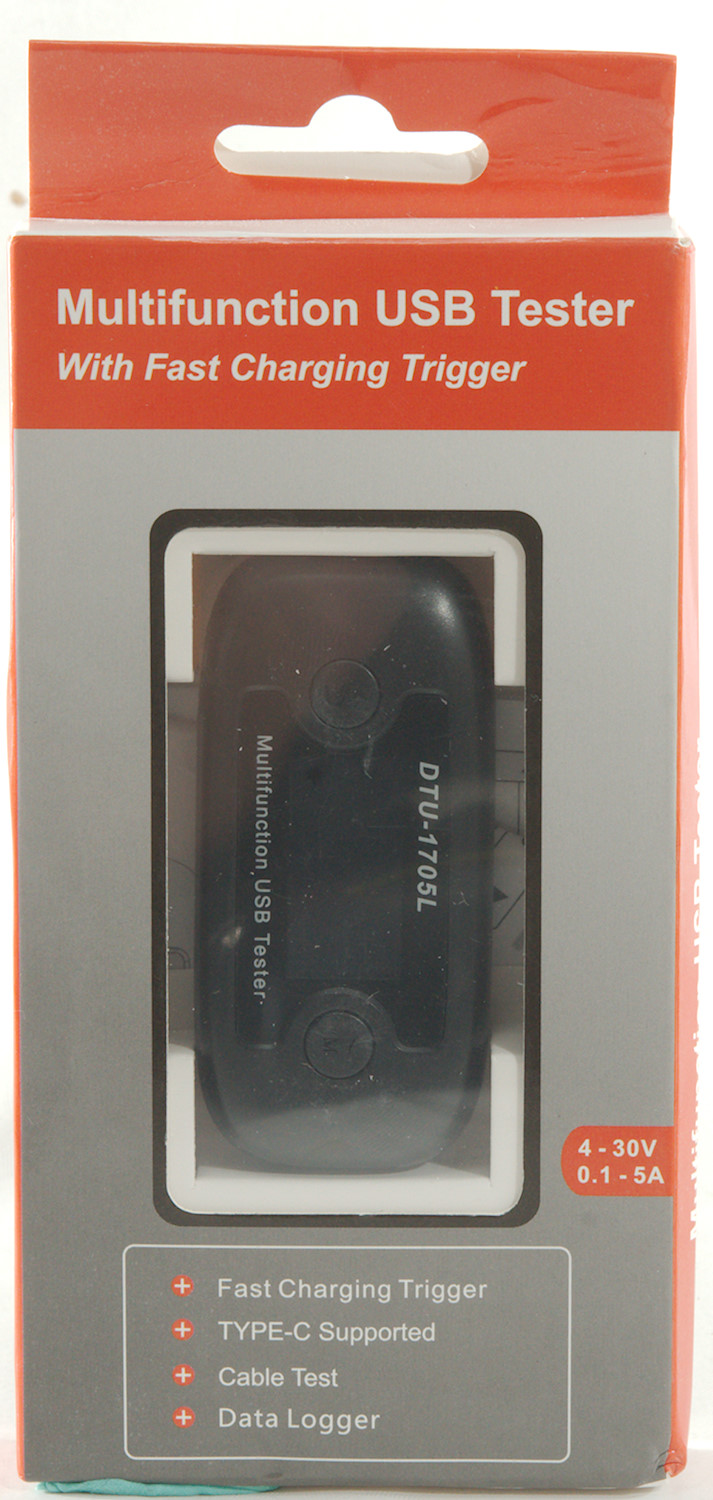
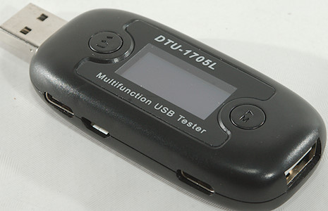
DTU-1705L USB Tester
Official specifications:
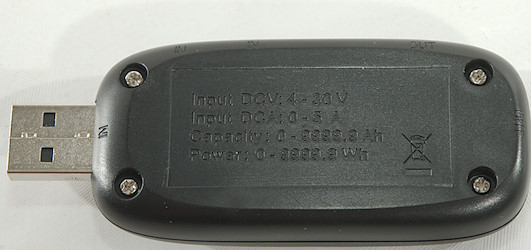
- Input voltage: DC 4 - 30V
- Input current: DC 0 - 5A
- Voltage resolution: 0.001V
- Current resolution: 0.001A
- Voltage accuracy: 0.2% + 2
- Current accuracy: 0.3% + 2
- Power consumption: 6-10mA
- Internal resistance: 55 - 65mOhm
- Capacity counter: 0 - 9999.9Ah (Resolution: 0.0001Ah)
- Power counter: 0 - 9999.9Wh (Resolution: 0.0001Wh)
- Timer range: 0 - 999mins
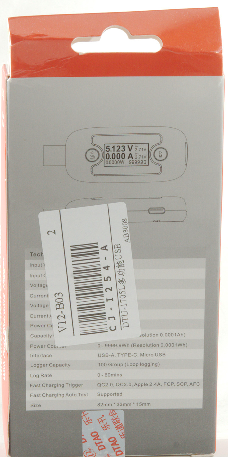
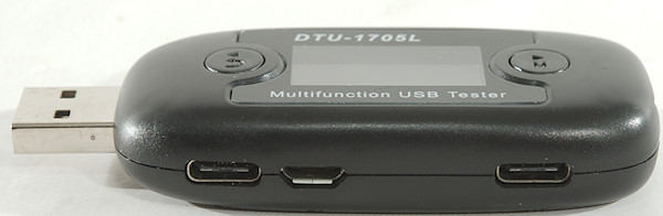
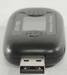
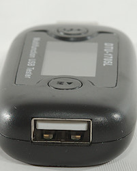
- Interface: USB-A, TYPE-C, Micro USB
- Logger capacity: 100 group
- Log rate: 0 - 60min
- Protocol: QC2.0, QC3.0, Apple, HuaWei, Samsung
- Size: 82mm x 33mm x 15mm
This is a USB meter with protocol trigger.
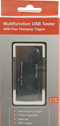

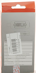

I got the meter in a cardboard box, with specification on the back.
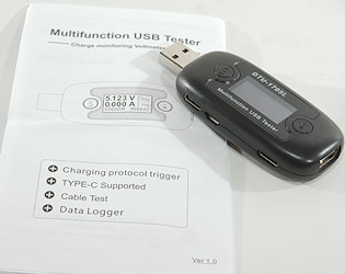
It contained the meter and a instruction sheet in English and Chinese.
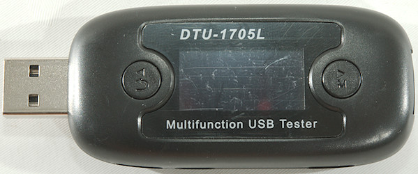
The user interface is fairly simple, short presses on the two button changes screen or steps a value up/down, longer presses will activate/cancel configuration.
Display and functions
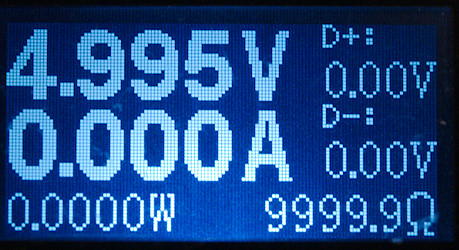
The main screen with voltage, current and power. There is also data line voltage and load equivalent resistance.
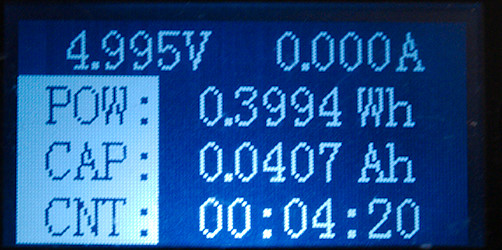
Voltage and current with power, capacity and time.
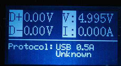
Protocol analyzer, shown detected protocol, voltage on data lines.
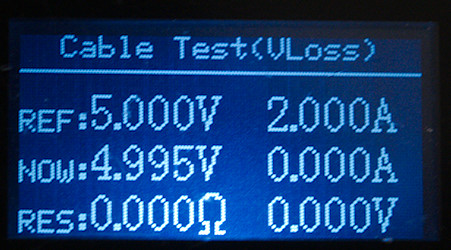
Calculate resistance in a cable, this requires a constant load and a stable usb supply. Then the reference voltage can be stored with load and without cable, adding the cable when reference is stored will show the resistance in cable and connectors.
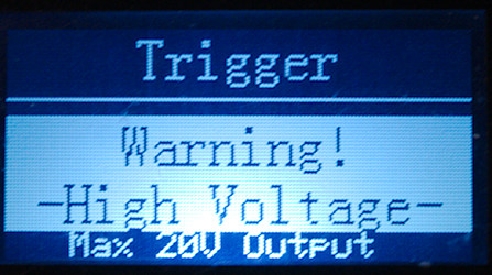
Protocol search and trigger, hold down button to activate.
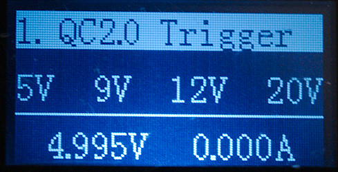
Each supported protocol has a trigger screen.
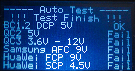
After the trigger screens is the auto detect mode. This screen is remembered when power is removed.
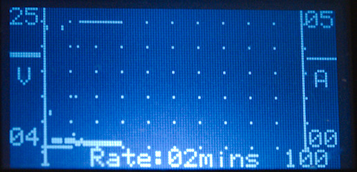
The charting function is designed to show a full charge curve, the fastest update rate is once a minute. The curve is saved.
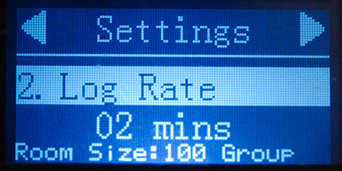
There are a couple of configuration screens, Voltage, current, time out, log rate, back light, factory reset.
Measurements
- USB-C output will not be triggered when this device is used.
- USB-C output cannot be triggered from another device.
- The usb meter uses about 9mA current with backlight on.
- The internal resistance is about 0.095ohm (This includes both connectors).
- Usb meter will remember measured values when power is removed.
- Backlight timeout can be adjusted in 20s, 40s, 60s, always
- Voltage display is within the rated 0.2% when no current is flowing.
- Current display is within the rated 0.2% up to 3A, but more like 1.5% at 5A
- Minimum current before display shows current is about 0.18A, but is first precise at around 0.2A
- Curve update is in minutes, i.e. the curve is more than an hour at fastest setting
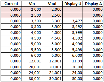
The voltage display is very precise with no current flowing.
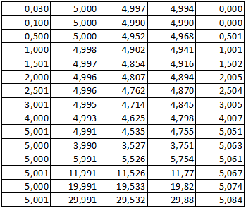
The current display is also very precise up to 3A, then the precision drops some.
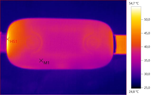
M1: 36.7°C, HS1: 54.7°C
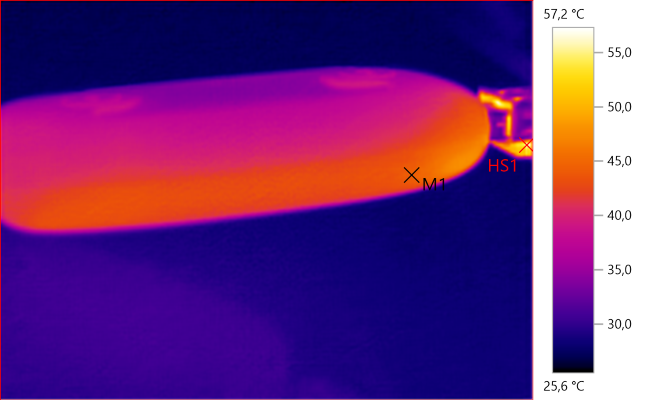
M1: 44.5°C, HS1: 57.2°C
The above IR photo was taken after 30minutes with 5A.
The current varies with temperature, I got 1% change after 30 minutes with 5A.
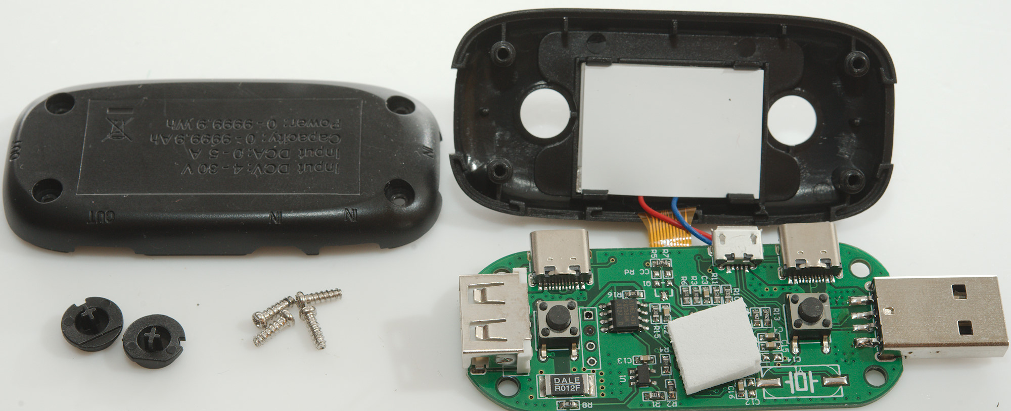
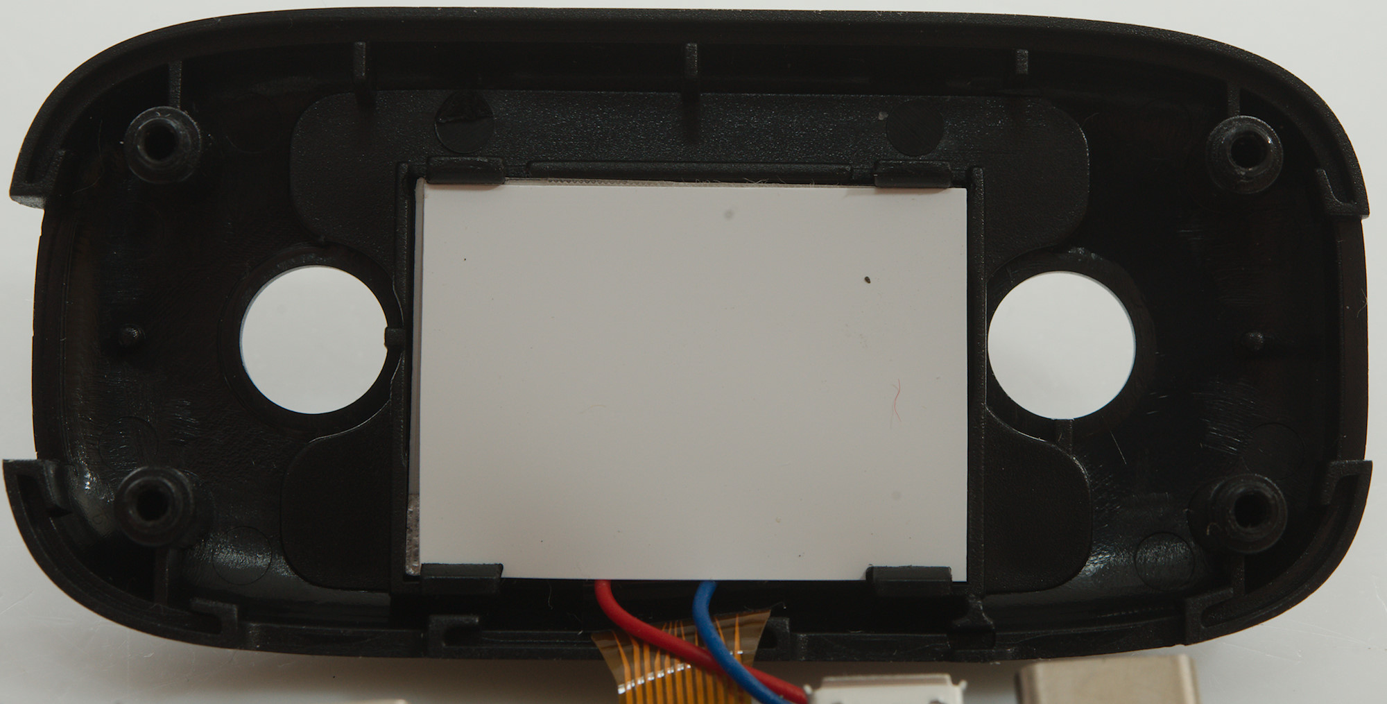
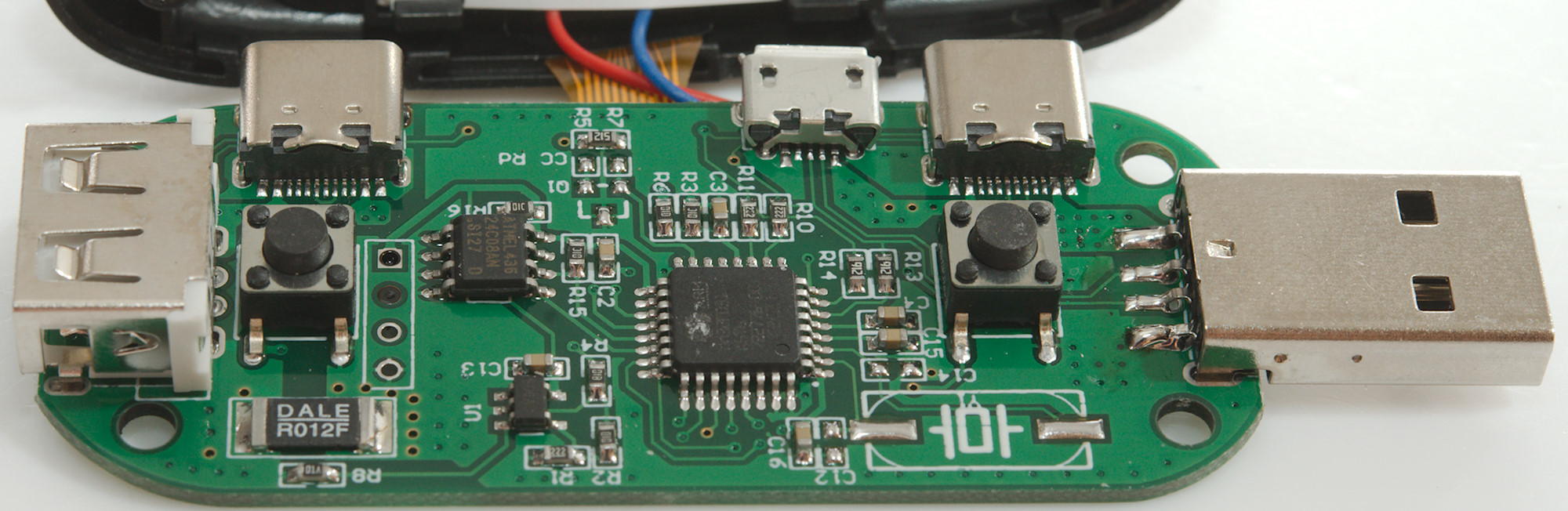
Tear down
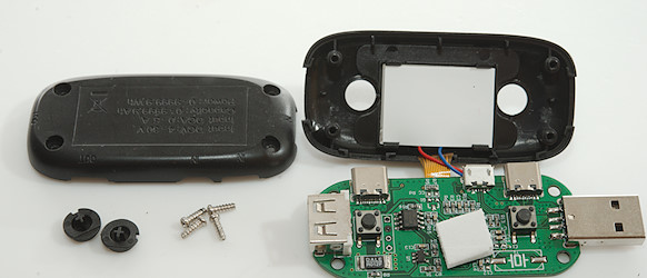
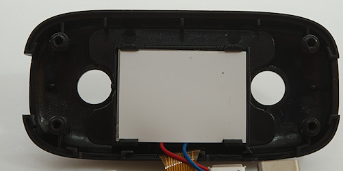
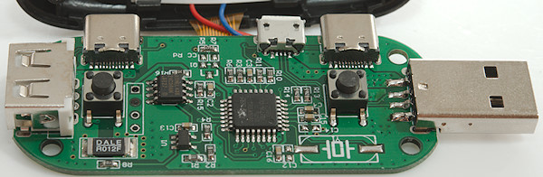
It was easy to open with four screws. Notice the two buttons are not the same, this prevents assembly faults.
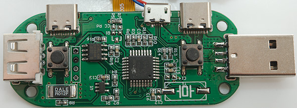
The meter is based around a microprocessor (MM32F031K6T Arm M0), with support from a EEPROM (U4: 24C08AN) and a OpAmp (U1; marked S06AC) to amplify voltage from current shut. The current is measured across a 0.012ohm (12mOhm) resistor. The MPU uses internal 12 bit ADC. The microprocessor uses internal clock oscillator in this circuit, this means the Ah and Wh will be less precise.
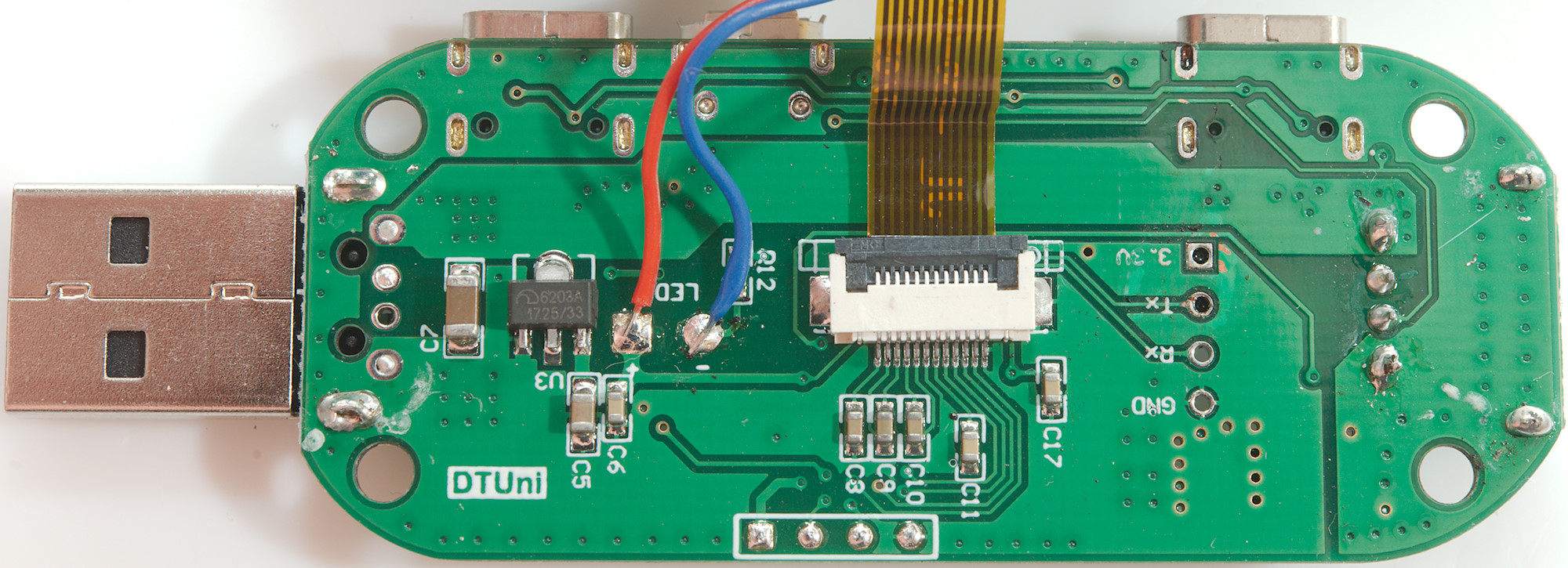
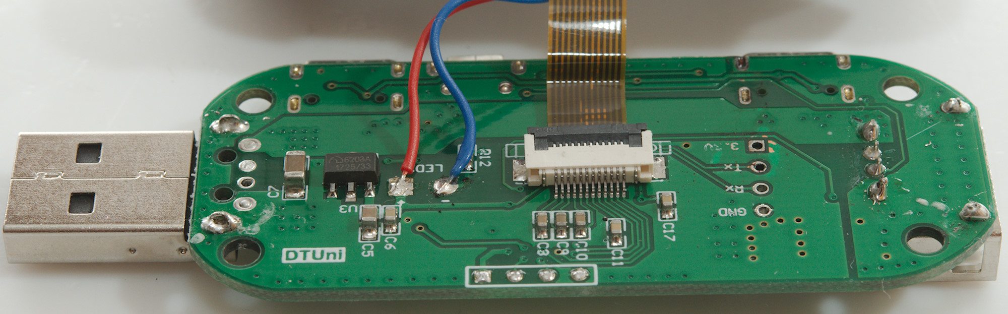
And what is the extremely small resistor that is between C13 & U1?

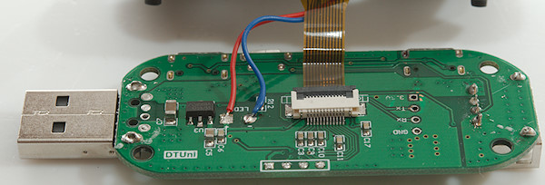
On this side is the voltage regulator (U3: XC6203A 3.3V). According to the markings on the circuit board there may be a serial port available (A check with an oscilloscope did not show any data).
Conclusion
A usb meter with protocol analysis and trigger. The chart can be rather useful with the slow time scale, it will show the full charge curve for a phone or tablet. The USB-C functions do not really work.
I like the used interface, it is fairly easy to use, but I do not like that it need about 0.2A before it will show something.
Notes
For these USB meters I used precise equipment (Keithley: DMM7510, 2280S, Keysight: 34470A).
How do I make the test