Using a Arduino with Test Controller

DSC_4211

In addition to all the test equipment TestController can handle, it is also possible to make your own using an Arduino. This home made equipment can be combined with all other test equipment and logged and/or controlled from TestController.
The code included here is an example and do not do anything, except establish communication between a Arduino and TestController. It is also done as simple as possible.

Contents
    Requirements
        Arduino Nano
        Arduino ProMicro
        Adding isolation
    Arduino program
    TestController definition
        How do it look in TestContoller
    Conclusion
    Notes & links
TestController main page


Requirements

The basic requirement is a Arduino with a (virtual) serial port, nearly all Arduinos and clones qualifies for that. I often uses a Nano or ProMicro (This is not a real Arduino), they are both fairly small and can easily do simple data acquisition and control.
The inputs and outputs are not isolated from the controlling PC, in some cases this may be an issue.


Arduino Nano

DSC_4212

Basically the same as a UNO, but in a much smaller size. The USB connection is controlled by a extra chip, this means the baudrate is fixed and for TC I recommend using 9600 to support the "Scan serial ports" functions.
It uses a mini USB connector.

DSC_4217

For people that prefer USB-C connectors Seed-Studio makes a "Seeeduino Nano" that has exactly the same processor and pins as the nano, but uses a USB-C connector. I take a look at it here


Arduino ProMicro

DSC_4213

This uses the same hardware as Arduino Leonardo, but is much smaller and not a official Arduino model. Because the USB port is build into the processor there is no baudrate, i.e. it will response at any baudrate and communication will be as fast as possible.
It uses a micro USB connector. This board exist in both 3.3V and 5V versions, I usually uses 5V, but the 3.3V is useful for interfacing to 3.3V sensors.
This is usually my preferred Arduino, due to the mini USB and no baudrate requirement. The build-in peripherals are slightly better than the nano (Two 16 bit timers and more analog inputs).


Adding isolation

DSC_4214
DSC_4215
DSC_4216

This isolation adapter can be found on ebay (Search for "USB To USB Isolator") and can be used on the USB connection between the PC and Arduino, it will add low voltage isolation and break ground loops, but do not use it for mains.


Arduino program

TestController implements many different protocols, for this a very simplified SCPI is the easiest one to use.

Code:
#define BRAND "HKJ"
#define PRODUCT "Test"
#define SW_VERSION 1
#define SERIAL_NUMBER 1

// Maximum command length and buffer
const int BUF_SIZE = 50;
char cmdBuf[BUF_SIZE];

// Settings
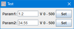
double param1 = 1.2;
double param2 = 34.56;

void setup() {
  Serial.begin(9600);
  // The next two lines are only needed on processors with build in USB
  unsigned long t = millis();
  while (!Serial && millis() - t < 3000); // Wait for USB connection to get ready, but do not hang when running without USB
}

// The loop must not use delay() or delay in any other way, it has to run through in a small fraction of a second for best performance
void loop() {
  if (Serial.available() > 0) {
    int n = Serial.readBytesUntil('\n', cmdBuf, BUF_SIZE - 1);
    if (n > 0) {
      *(cmdBuf + n) = 0;
      strlwr(cmdBuf);
      char* cmd = strtok(cmdBuf, " ");
      if (strcmp(cmd, "*idn?") == 0) {
        Serial.print(BRAND);
        Serial.print(',');
        Serial.print(PRODUCT);
        Serial.print(',');
        Serial.print(SERIAL_NUMBER);
        Serial.print(',');
        Serial.print(SW_VERSION);
        Serial.print('\n');
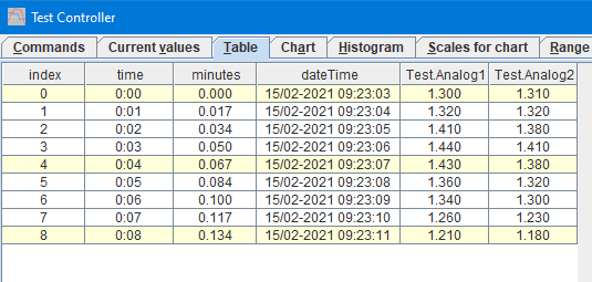
      } else if (strcmp(cmd, "values?") == 0) {
        // This command returns all values that has to be saved in the table and used to draw curves from
        Serial.print(analogRead(A1) * 5.0 / 1024);
        Serial.print(' ');
        Serial.print(analogRead(A2) * 5.0 / 1024);
        Serial.print('\n');
      } else if (strcmp(cmd, "param1?") == 0) {
        // Read a parameter, the read value must preferable be the same as the write value
        Serial.print(param1);
        Serial.print('\n');
      } else if (strcmp(cmd, "param2?") == 0) {
        Serial.print(param2);
        Serial.print('\n');
      } else if (strcmp(cmd, "param1") == 0) {
        // Write a setting to a parameter, it is best to have matching read and write commands.
        char *p = strtok(NULL, " ");
        if (p != NULL) {
          param1 = atof(p);
        }
      } else if (strcmp(cmd, "param2") == 0) {
        char *p = strtok(NULL, " ");
        if (p != NULL) {
          param2 = atof(p);
        }
      }
    }
  }
}

For the BRAND use something that do not match any commercial test equipment brands, NAME can be anything. The combination of BRAND and NAME must be unique for this device. SW_VERSION and SERIAL_NUMBER are not really used, but can be shown in TestController. Note: SERIAL_NUMBER can be used to lock the device handle to a specific device with the "Remap handles" function in TestController.

The loop read from the serial port expect a newline termination, any background processing can be done while the serial port is empty. The received commands are converted to lower case and split at spaces (The very old C function strtok do that nicely). All commands that ends with a ? must return a answer, the other commands can just do something locally.
The loop must run fairly fast (At least 10 times each second, preferable much faster) or TestController will be slow to response. This is important when processing the "values?" command.


TestController definition

The definition must be placed in "...\doc\TestController\Devices" (On a Windows PC) in a file that has a .txt extension. It is recommended to use the BRAND and NAME for the file name.

Manual for definitions is here

Code:
; TestController must be restarted before any changes in this file will be used.

; Manual is here: https://lygte-info.dk/project/TestControllerConfigDevice%20UK.html

#idString HKJ,Test,
#name HKJ Test
#handle Test
#port comfixedbaud
; Devices with 9600 baud will be automatic found if "Scan serial ports" are checked
#baudrate 9600

; A list of possible column name with unit and formatter (SI, Time, Int, D0..D9, X1..X9) 
; See here for all formatter types: https://lygte-info.dk/project/TestControllerConfigDevice%20UK.html#Data_type_definitions
#value Analog1 V D3
#value Analog2 V D3

; How to poll for data, this is used for table and #values?
; a #askMode, #cmdMode and #prepareSample is used before this is string is used.
; Number of returned values must match number of columns defined with #value
; This is a single line command
#askValues values?

; See here for all control types: https://lygte-info.dk/project/TestControllerConfigDevice%20UK.html#Configuration_menu
;The "V 0 500" line is: unit minimum_value maximum_value
#cmdSetup number Param1
:read: param1?
:write: param1
V 0 500

#cmdSetup number Param2
:read: param2?
:write: param2
V 0 500

The #idString must match "BRAND,NAME" from the Arduino program or the device will not be loaded.
The #name is usually a more readable form of "BRAND NAME" and must be unique, TestController will only accept one definition for any #name
The #handle is a short form of the name that can be used as a variable. This do not have to be unique, but because it is used to match column formats when loading .csv files, it is best if it is.

There must be a #value definition for each value returned by the #values? command.
For each adjustable value a #cmdSetup can be used to add the value to the "Setup" popup in TestController.


How do it look in TestContoller

TCValues

The input from two unconnected Arduino ADC channels.

TCLog

The input from two unconnected Arduino ADC channels here I log it.

TCSetup

The two configurations.

There are many other ways to see and control the Arduino device in TestController.


Conclusion

Using a Arduino can add extra inputs, this could be digital inputs, but also temperature, humidity, light, pressure or other signals where a sensor can easily be connected to a Arduino.
Another usage is controlling outputs, it can be as simple as turning a mosfet on or moving something around with a servo or stepper while TestController is logging.

Some Arduino devices will show up on my project page over time, they will include schematic, gerber files, Arduino program and TC definition.


Notes & links

TC assumes a Arduino is ready 2 seconds after the serial port is initialized, some Arduinos may be slower. To handle that add a "#resetDelay seconds" to the definitions or a "resetDelay=seconds" to the command line of TC.

TestController main page
TestController manual for definitions SCPI definitions
Projects, including Arduino library and devices for TestController
For analog input I have a ADS1115 ADC library (15 bits, 4 channels) that supports background conversion

Arduino code & TC definition