Multimeters and current measurements
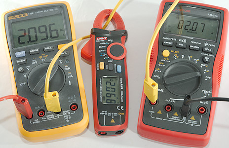
In this article I will look at different ways to measure current and at the pitfalls.
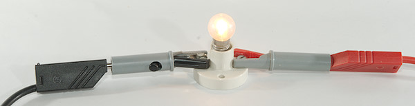
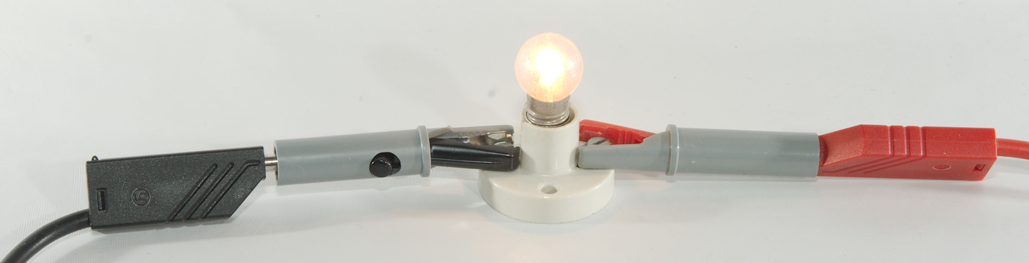
For demonstration I will use a very simple circuit with a single 6V 0.44A light bulb. The power supply will be outside the images and current will always arrive in the red and black wires. If something is difficult to see on the images (Like the meter display), click on the image for a larger version.
I will keep most of my test cables out of the pictures, but looking at the cable/connector colors will make it possible to track the cables.
Contents
Measuring with current clamp meter
Measuring with multimeter
A look at probes
Converting a multimeter to a clamp meter
Using resistors to measure current
Using a shunt to measure current
Measuring pulsing DC current
Measuring mains current
What to look for on a Clamp meter
What to look for on a multimeter
Conclusion
Notes
Measuring with current clamp meter
Current clamps are usual the easiest way to measure current, but there are some restriction:
- Current clamps cannot measure low current (uA).
- Current clamps are a bit unstable at lower currents (mA).
- Some current clamps are only for AC current.
- Current clamps are not precision equipment
But if these restriction can be accepted, it is easy.

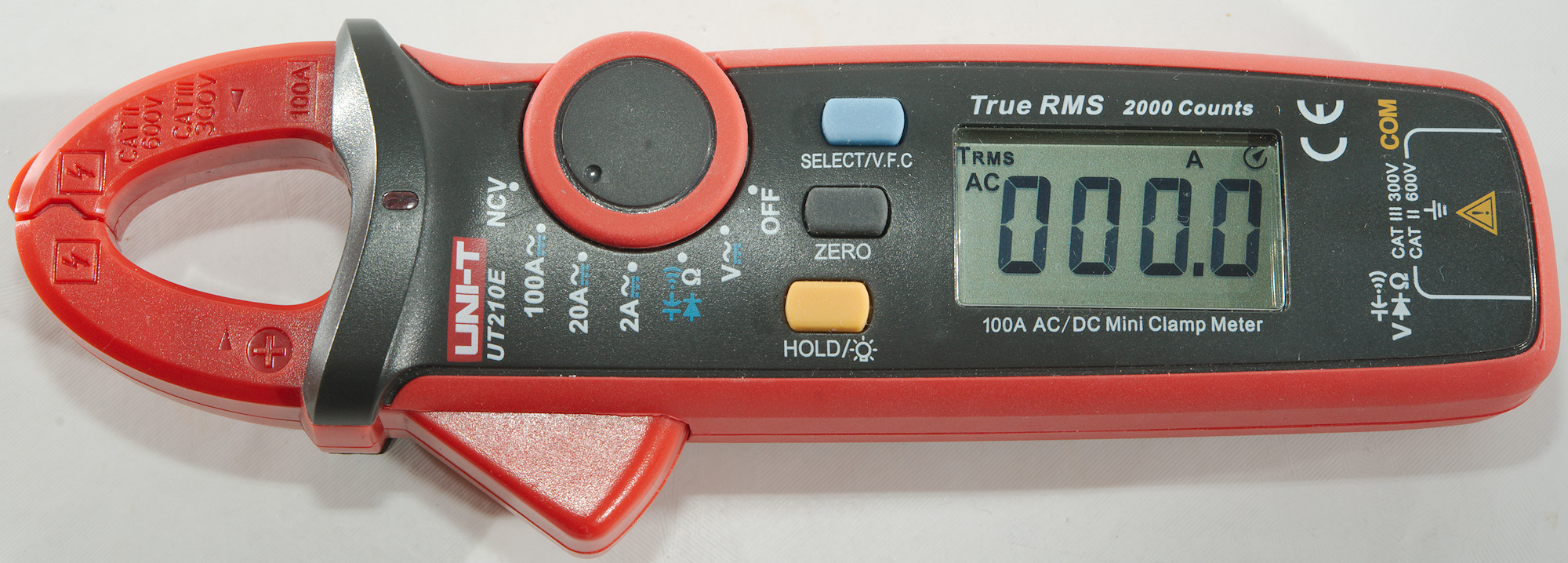
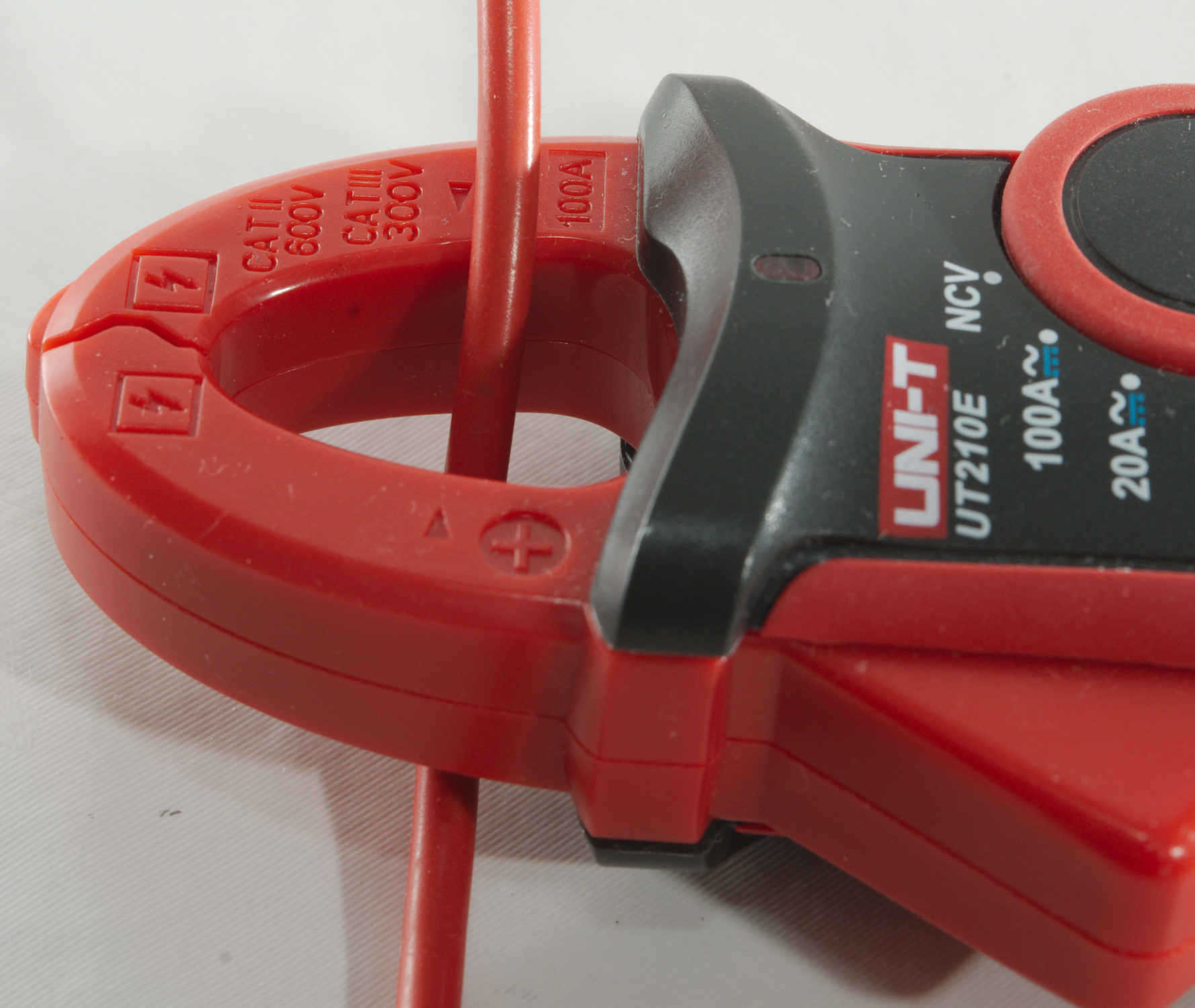
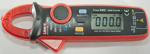
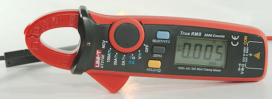
First the current clamp must be turned on and for this model DC must be selected.
There is a lot of current in the air today? Not really, current clamps always has a DC offset, that must be calibrated out.
This means pressing the "REL" or "ZERO" button and the display will show zero. It might be a good idea to let the meter "warm up" a couple of seconds first, then the zero will usual be more stable.

And the zeroing must be done with the meter in the same orientation as it is going to be used in, for best precision. Here is the display with some other meter orientation after the above zeroing. Current clamps measure magnetic fields and the earths magnetic field will affect it.

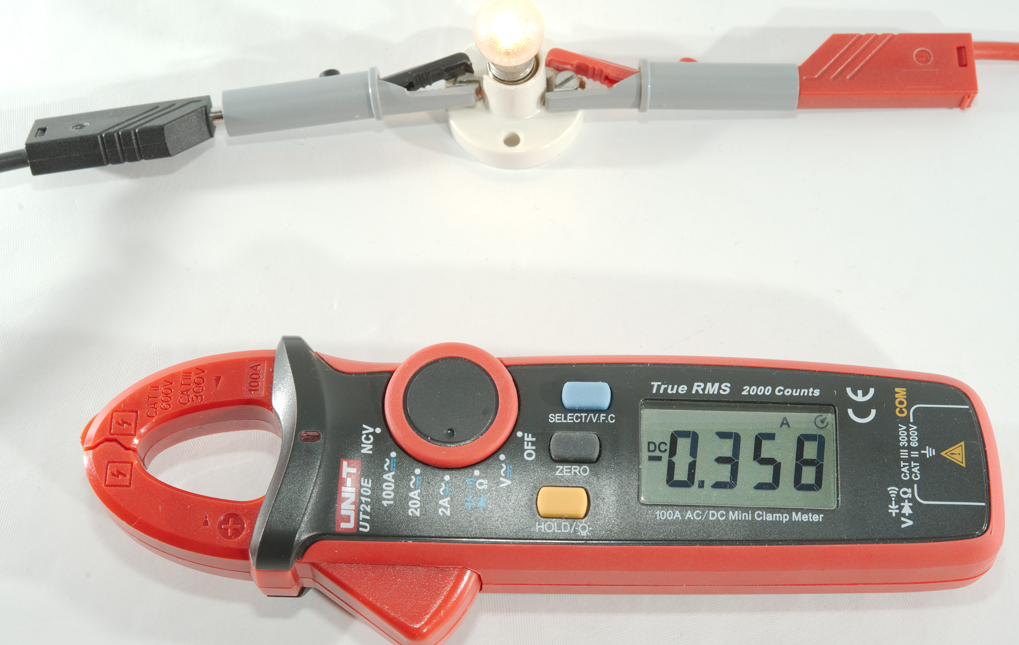
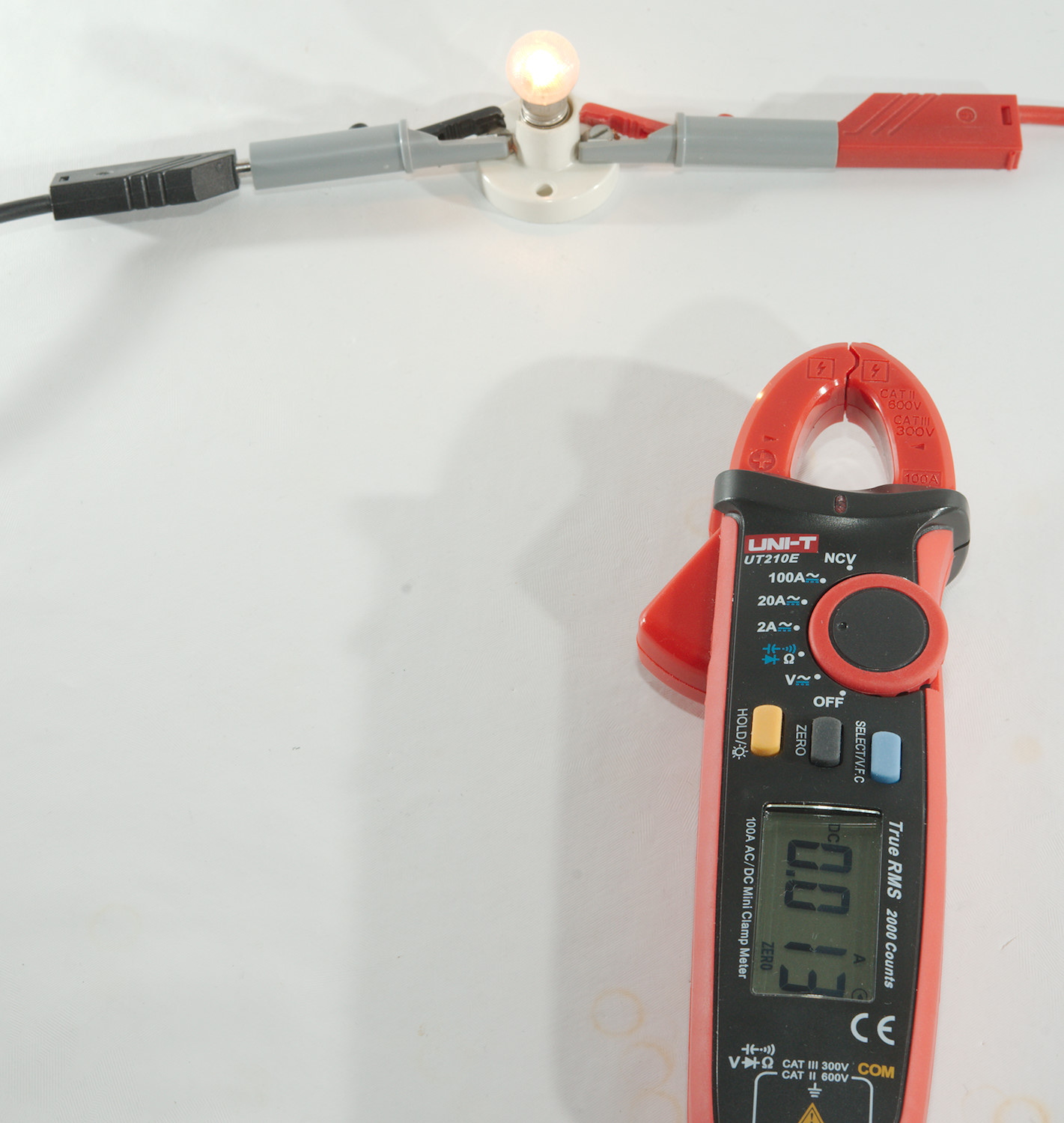
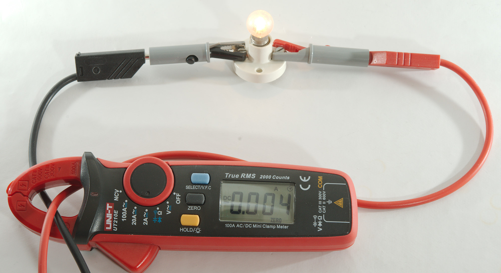
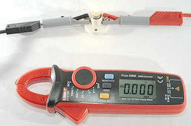
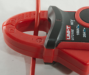
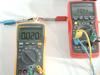
And then just clamp it around the wires to measure the current. The meter is a little bit out, the correct result is 0 current in the clamp. There goes 0.44A to the lamp and also 0.44A back again, the sum is 0. The above was to show that it is not possible to measure on a cable, you need access to the individual wires.

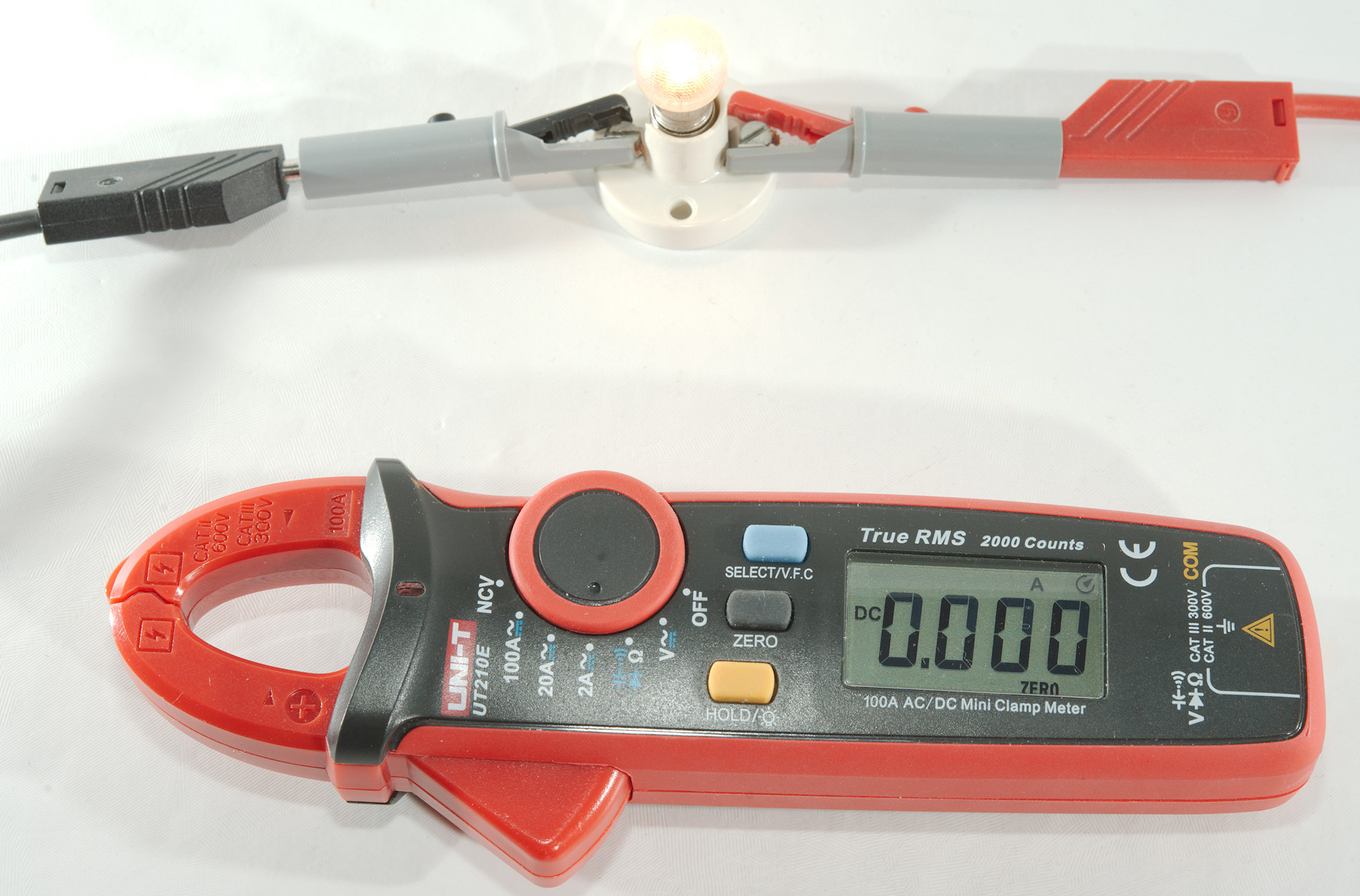
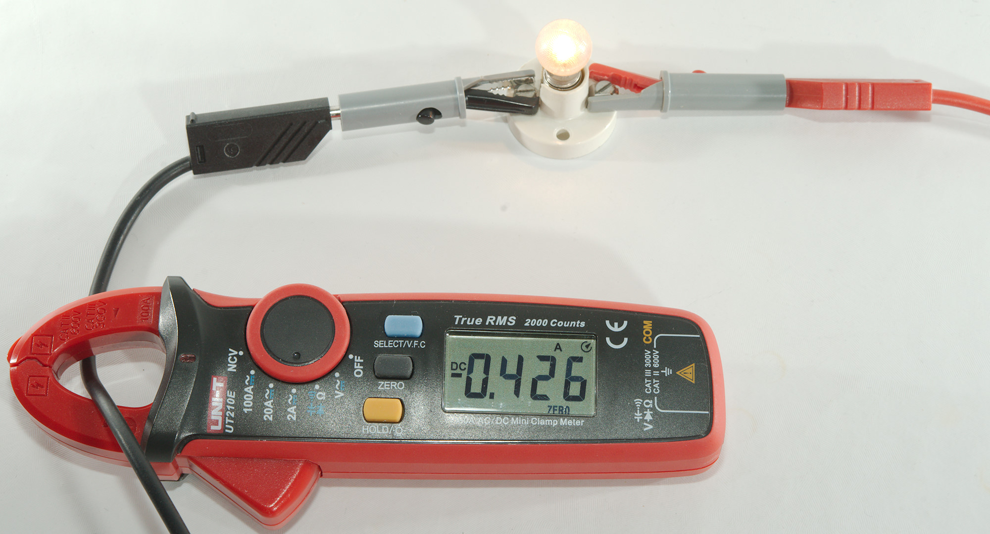
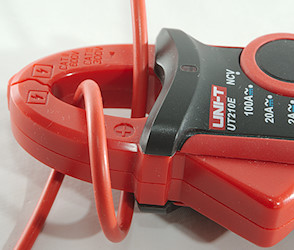
This is the way it must be done, a single wire through the clamp and it will show the current. Due to the direction it shows a negative result.
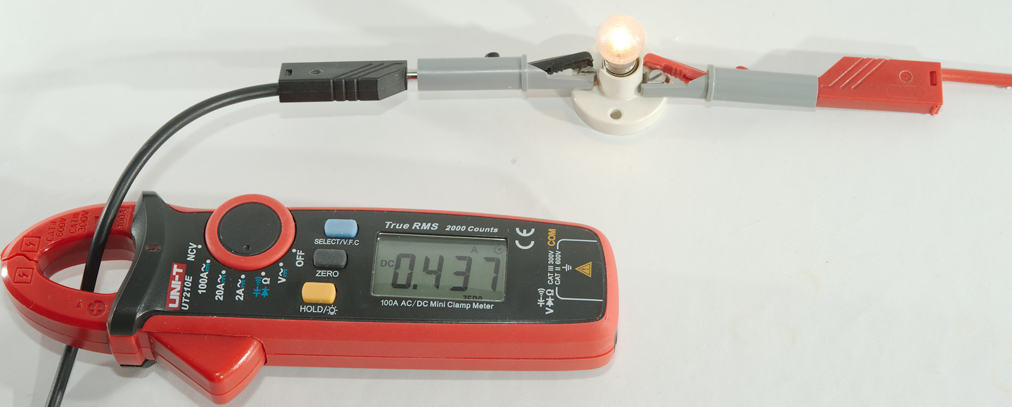
Routing the cable the other way through the clamp and the result is positive. The result varies a little bit, this can be due to the wire position in the clamp or it can be because the zero point has drifted.
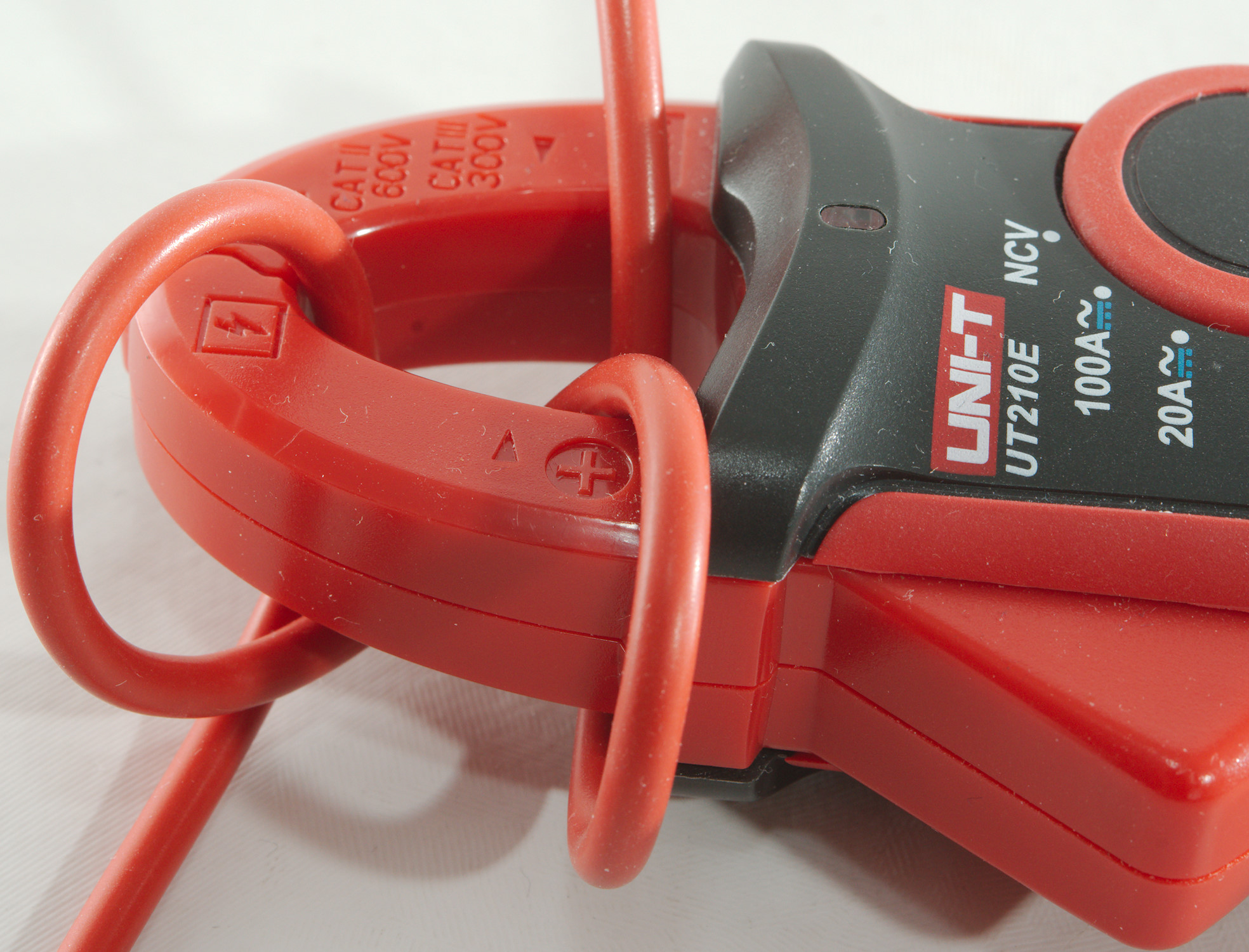
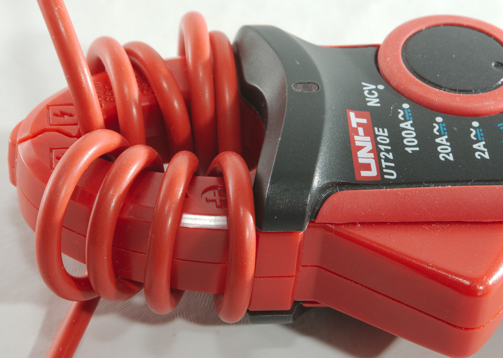
It is possible to increase the sensitivity of a current clamp by passing the wire through the clamp multiple times. One turn will double the reading.
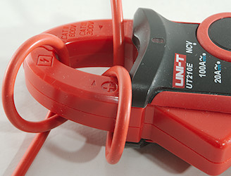

It is the number of times the wire goes through the center that is counted, i.e. here the actual current is 3 and 9 times less than the reading.
Measuring with multimeter
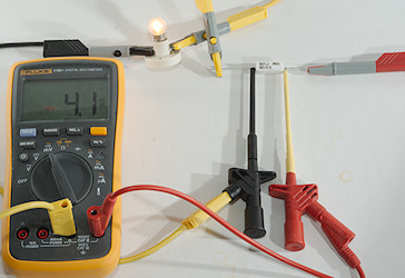
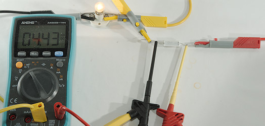
Most multimeters can also measure current, but this requires breaking the circuit.
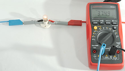
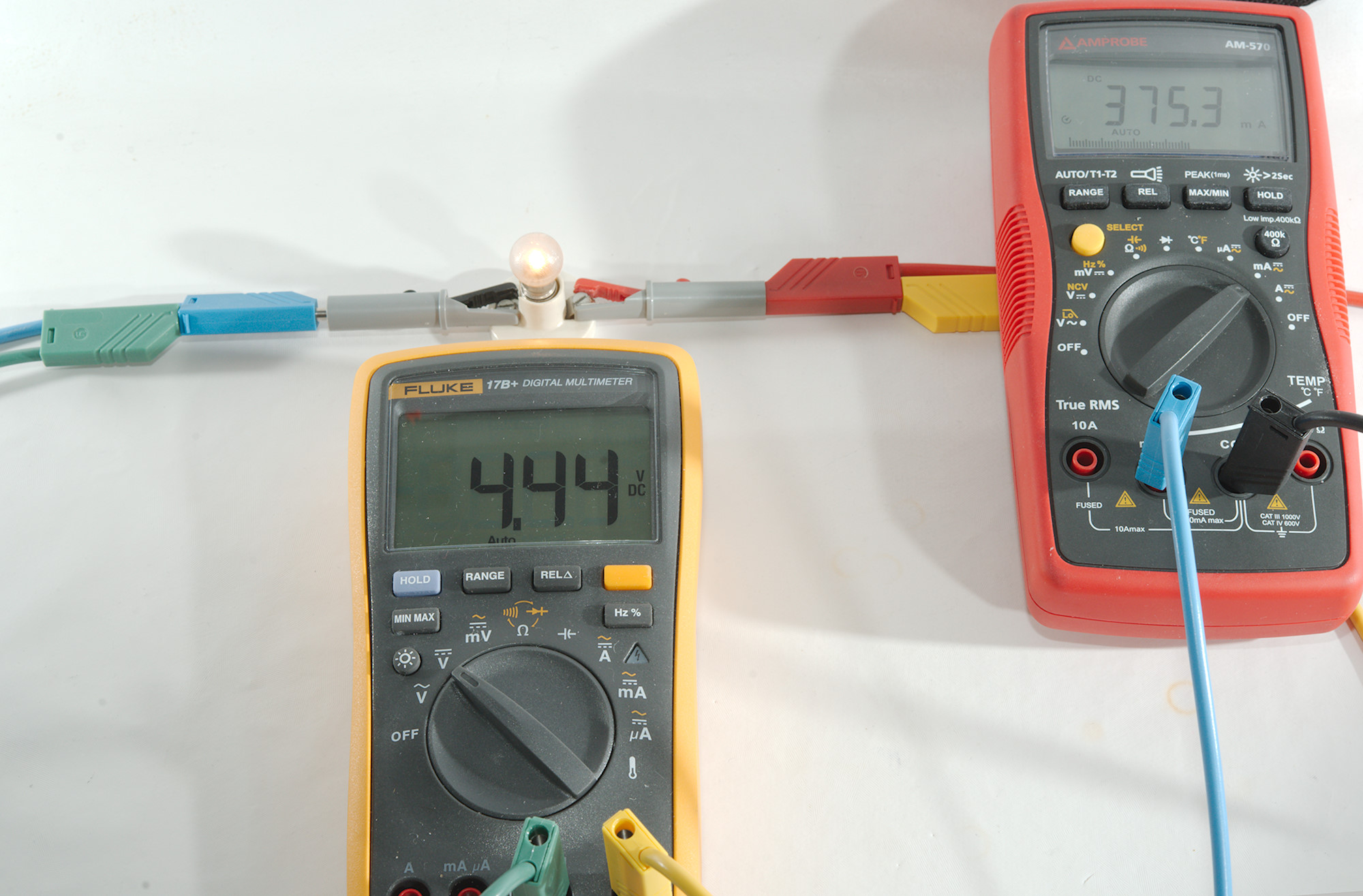
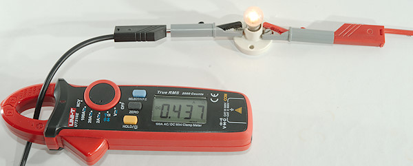
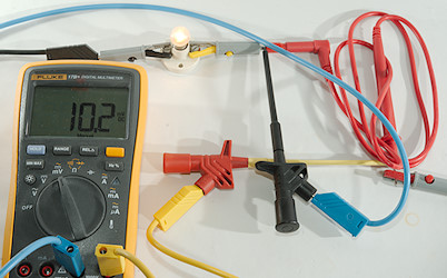
I have routed the current through the multimeter, but the current is considerable lower than the clamp result and is the lamp a bit less bright?

Luckily I have more multimeters and can check the lamp voltage while measuring current.
The voltage was supposed to be 6V minus any wire drop. I must have very bad wires with only 4.4 volt across the lamp or is there another explanation?
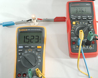
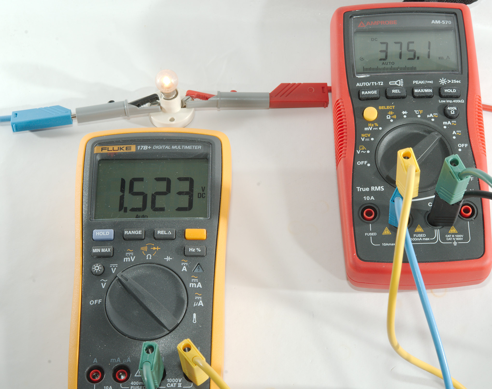
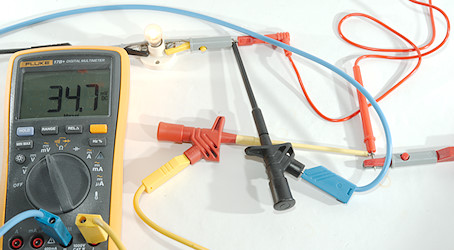
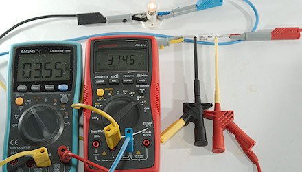
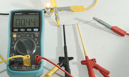
Here I am measuring the voltage lost in the ammeter, it is about 1.5V. This is a very common problem with multimeters that some current ranges will have a significant voltage drop. It is in the specifications, but often as mV/mA (or some similar unit), but 4mV/mA may not look that bad, before calculating on it.
Often it is the high mA range and the high uA range that is bad and the A, low mA and low uA are very good (I used this meter because I know it is very bad).
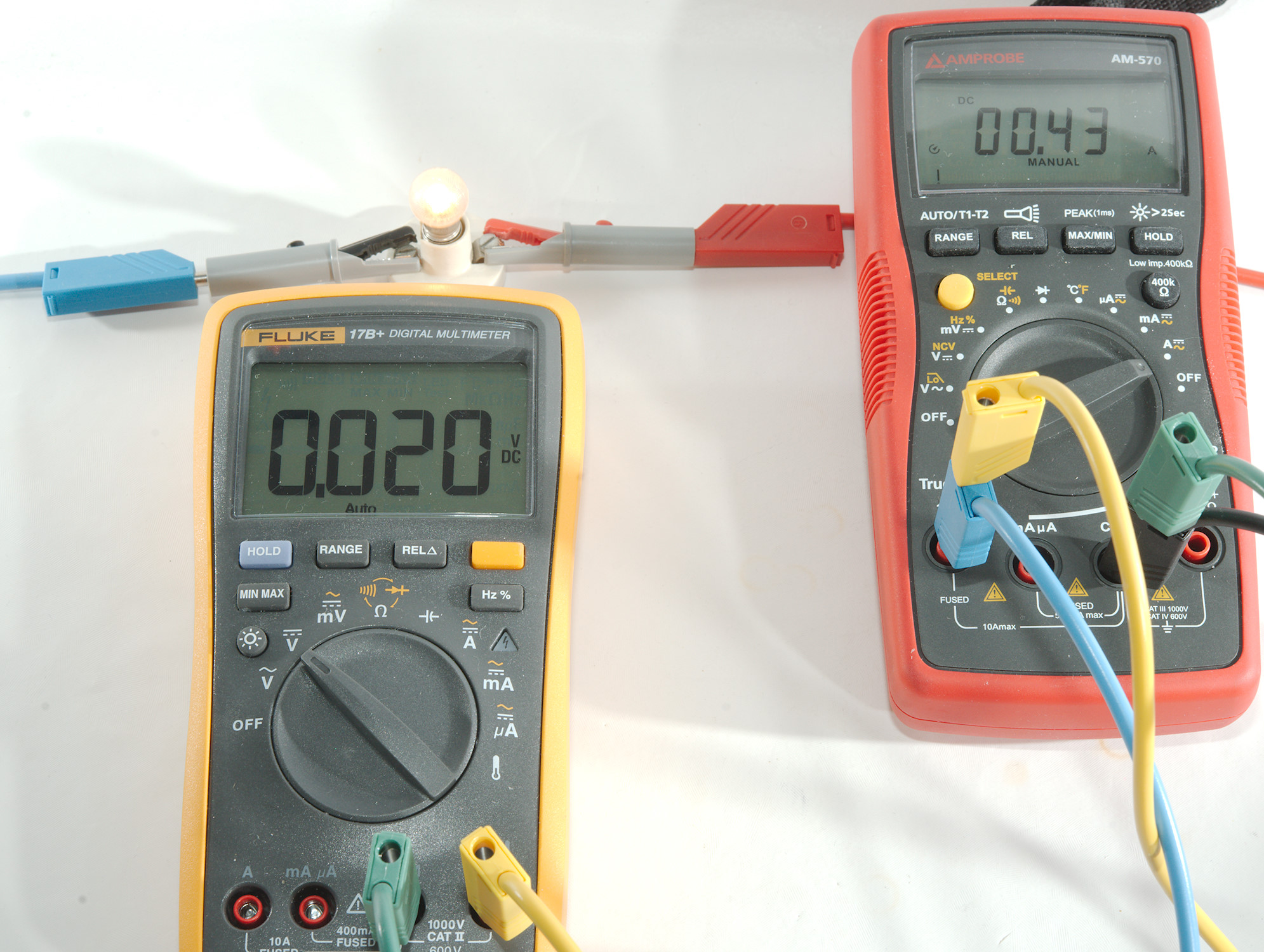
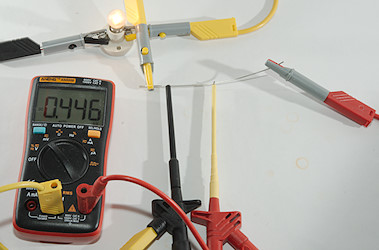
Using the 10A range instead gives much better result, but loses some resolution, especially because this meter is missing A range and only has the 10A range.
Here the voltage drop is only 0.02V, this means it can be ignore for most cases and the wires or probes may be the limiting factor.
A look at probes
I will only take a quick look at probes here, but it is possible to get the measurement for many probes in my multimeter reviews (Multiply the probe resistance by the current and by two for two probes to get the voltage drop).
The first probe is from a fairly good multimeter (The Amprobe from above, it is good even though the high mA range is not) and the voltage drop across one is 10mV with this load. This means two probes and multimeter in 10A range would be 0.04V drop at this current (0.44A), but using it at 10 times the current (4.4A) would be 0.4V and that would be significant in some tests.
What about probes from a cheap meter? Here the drop is 35mV for one probe or 0.07V for two. It would probably be acceptable in many cases, but higher current would be a problem.
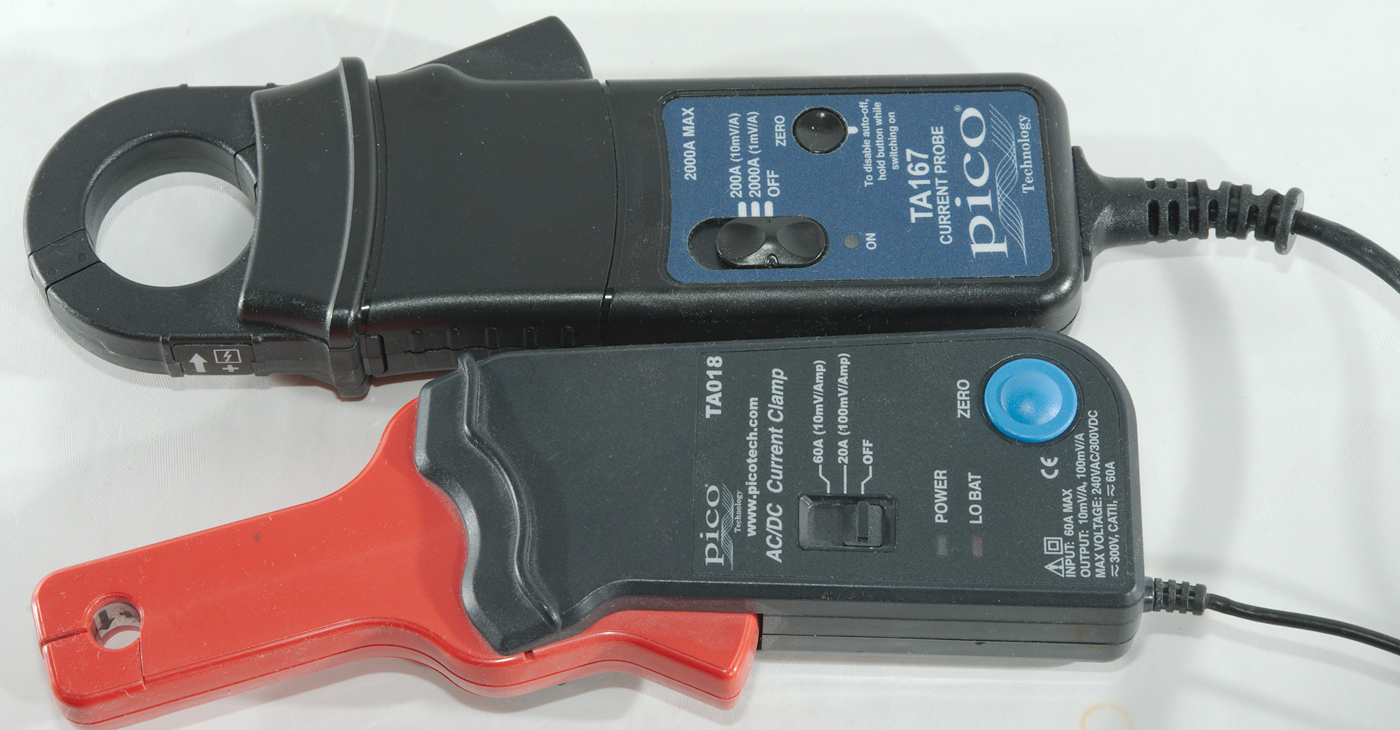
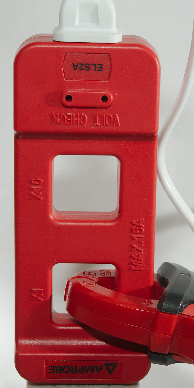
Converting a multimeter to a clamp meter
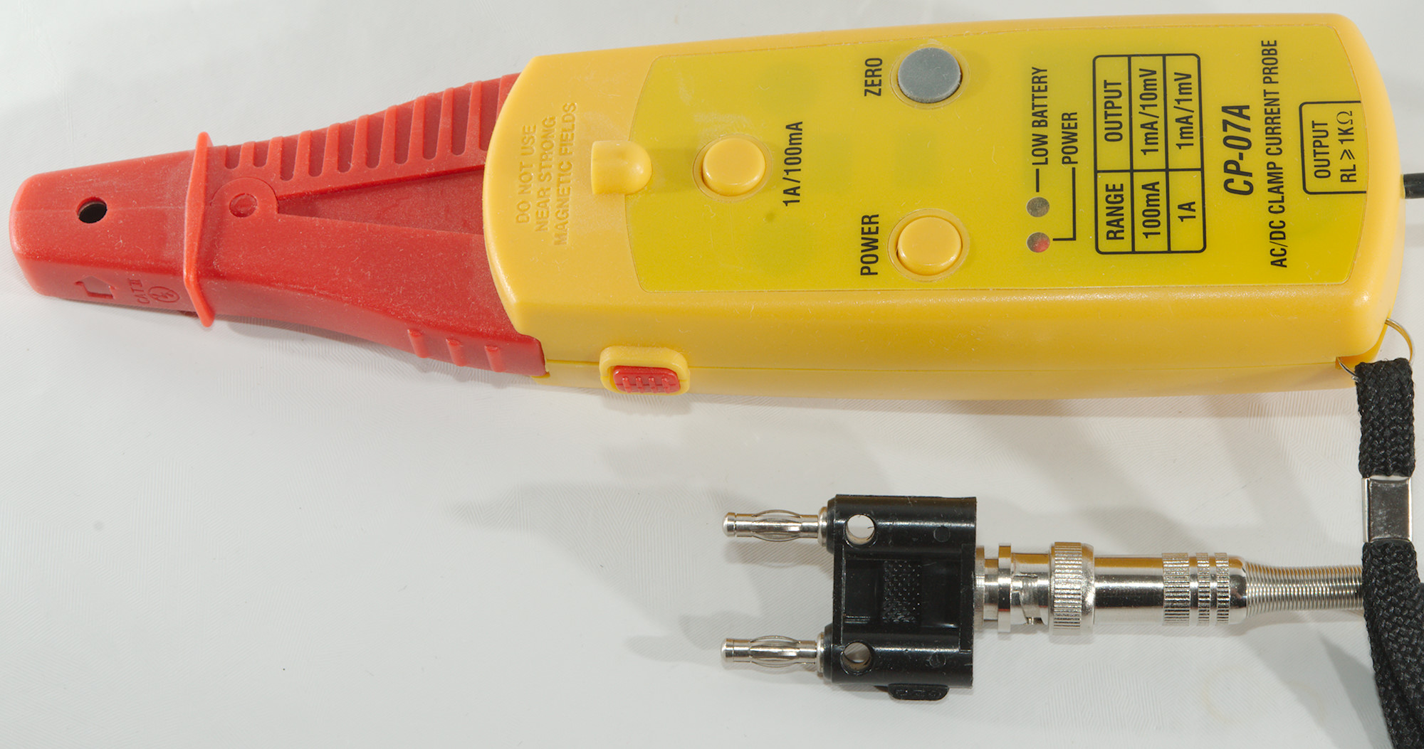
It is possible to get clamps without any readout, that can be connected to a multimer or a oscilloscope.
Mine is for oscilloscope connection, but an adapter can change that.
This clamp is not the one I usual use, but a clamp made for fairly low currents.
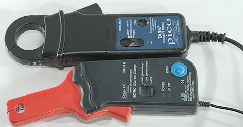
Here are two other clamps also for oscilloscope connection, again they can handle both AC and DC and cover a very wide current range (20A to 2000A full scale).
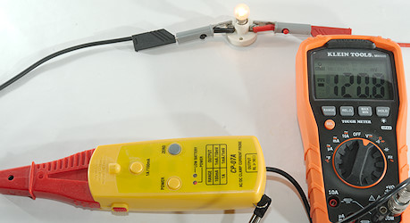
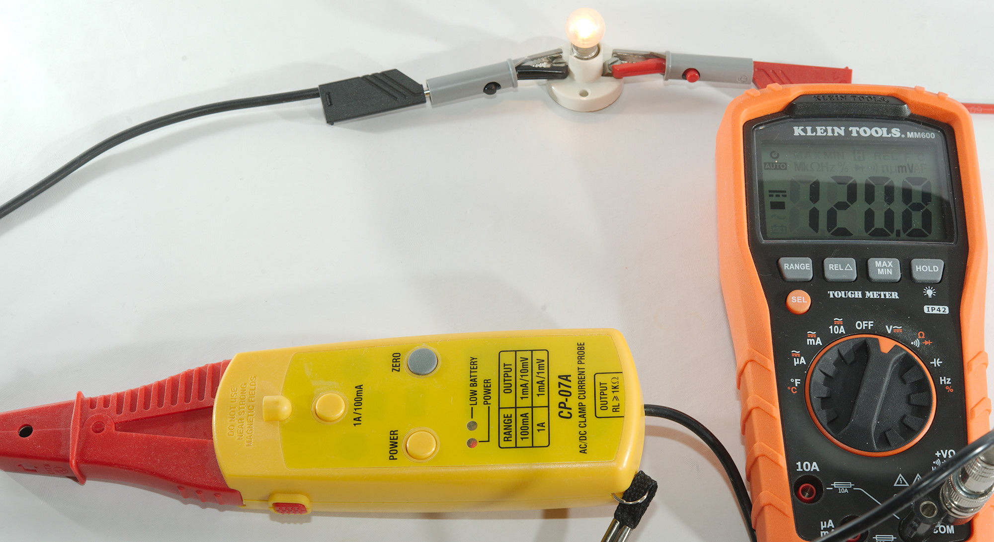
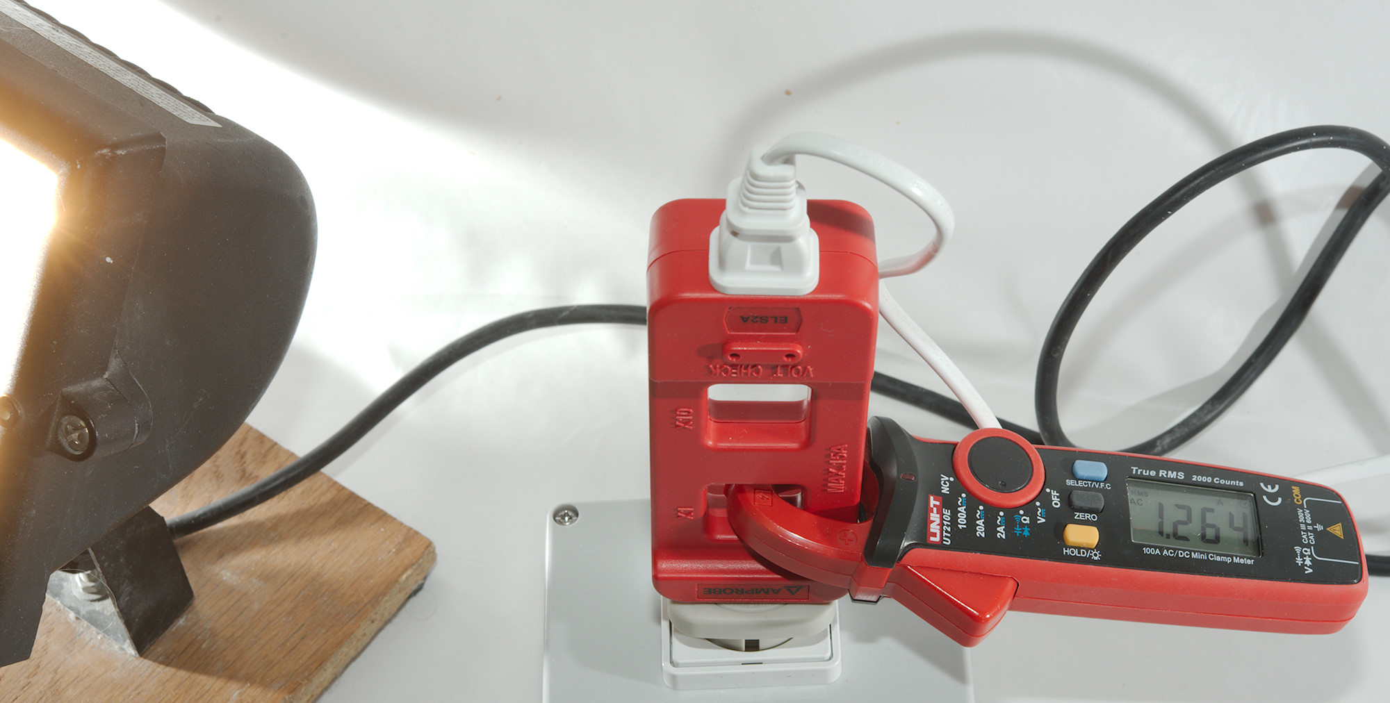
First plug the clamp into the meter and zero it. This works the same way as a stand alone clamp meter and has an offset before the ZERO button is used.
Then clamp it around the wire and measure the current, that will be shown as volt on the multimeter, you must apply the conversion factor specified on the clamp. In this case 1mA for each mV and the meter show 0.461V or 461mV, i.e. 461mA.
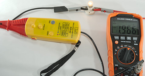
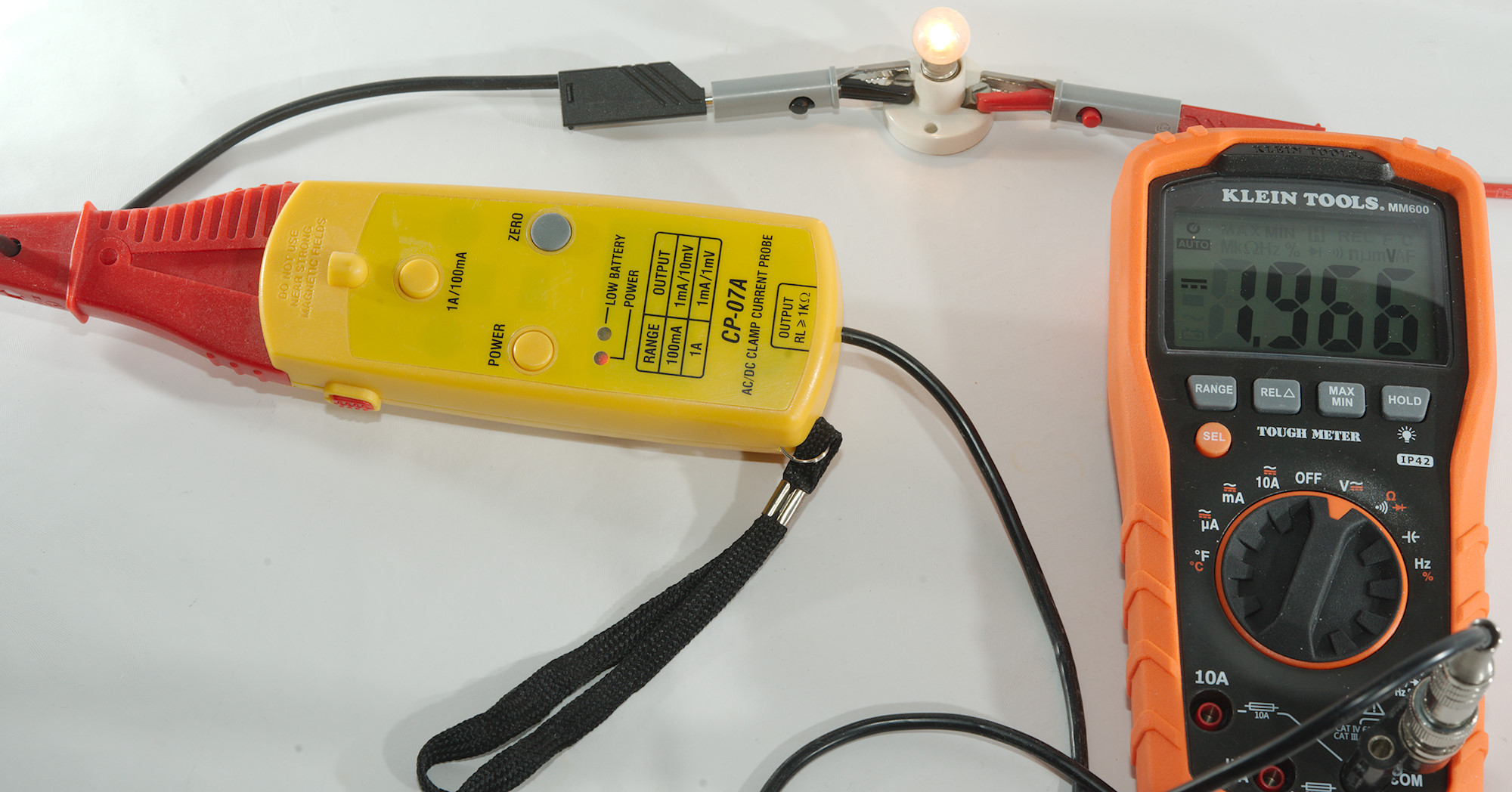
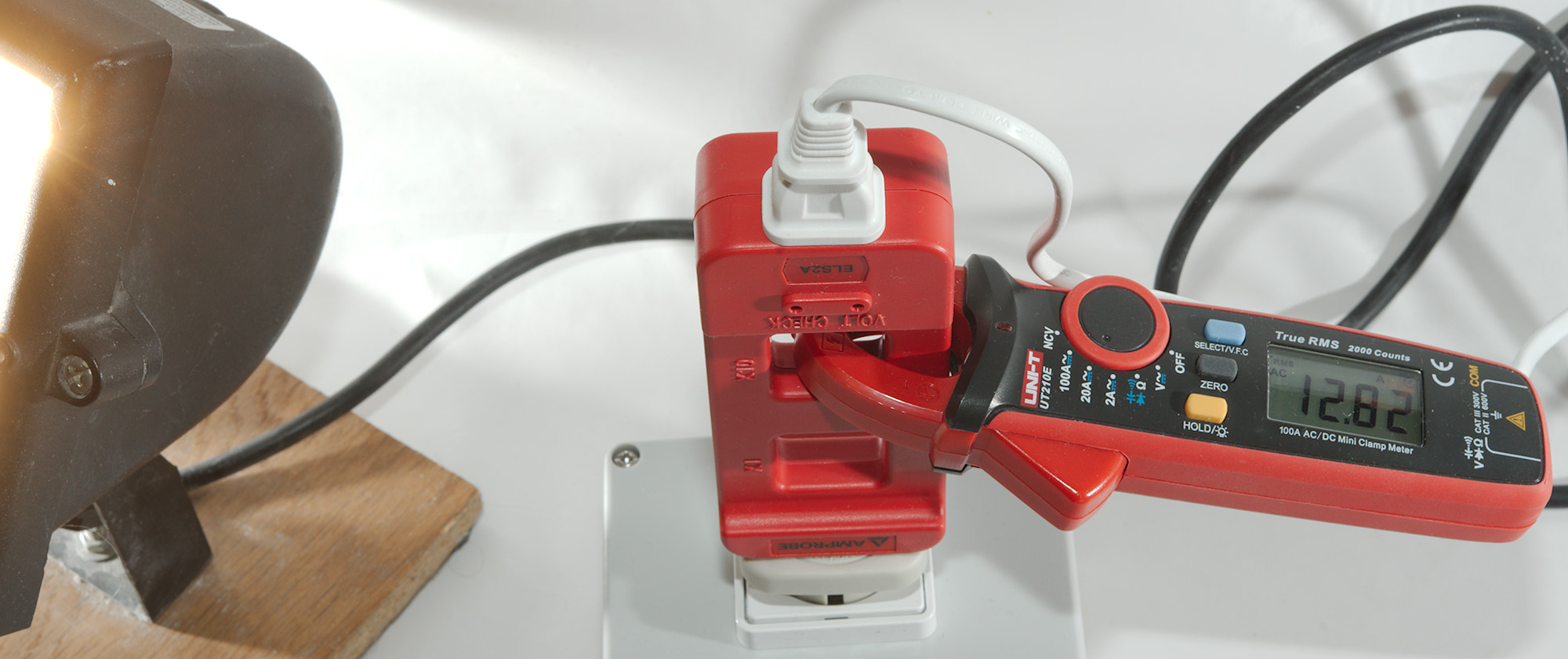
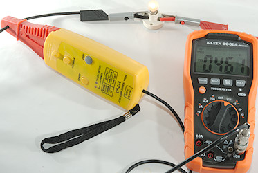
Watch out for the current range on the clamp, at over current you will get a wrong reading without any warning. Here I have selected the sensitive range and gets 1.966V, this would mean 196.6mA according to the range and is clearly wrong because I am overloading the clamp. This will not damage the clamp, but the result is useless.
Using resistors to measure current
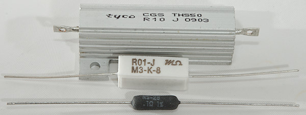
It is not necessary to use the current range on a multimeter to measure current, with a resistor the volt range can be used.
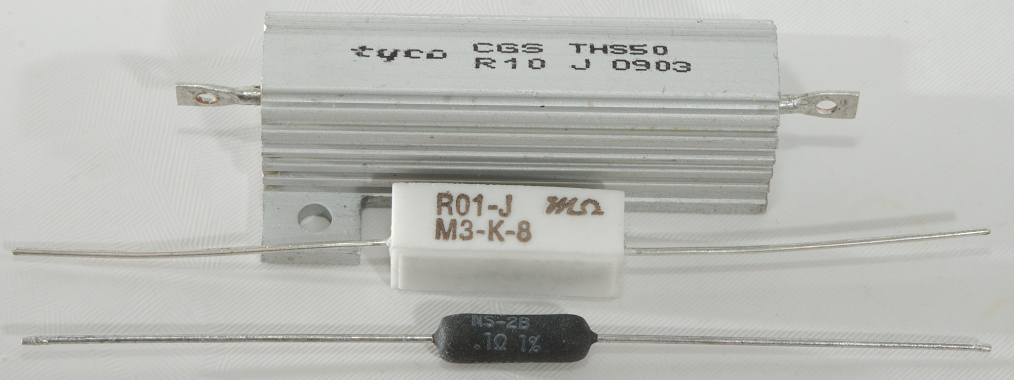
It is easiest to use round value like 1ohm, 0.1ohm, 1000ohm etc., other values can also be used to maximize resolution for a specific current, but this will require some calculations.
I only show resistor used for the bulb, but it can be used for both very low currents and very high currents, it just requires selecting a good resistor value.
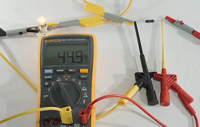
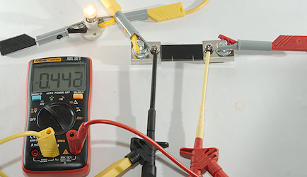
Here I am using a 0.1ohm 1% resistor in series with the bulb and there is 44.9mV across it. Using ohms low (Current=Voltage/resistance -> 44.9m/0.1 -> 449m) it is easy to calculate the current to 449mA and we already now that the voltage drop is 44.9mV.
For larger current it is possible to use a resistor that can handle more power, but they may give problems with the voltage drop.
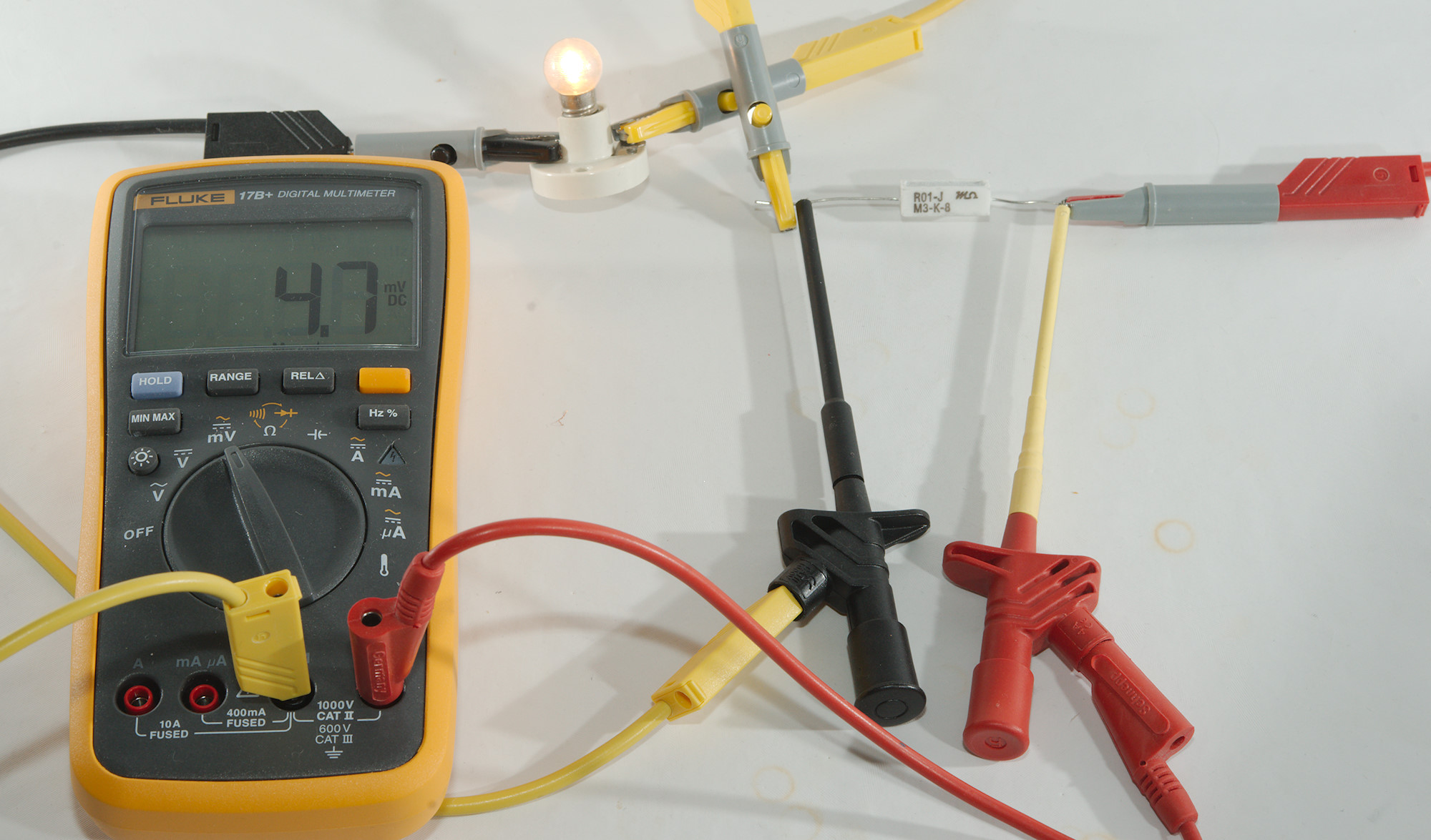
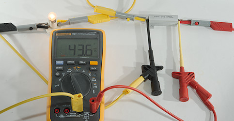
A lower value resistor may be a better solution, here I use 0.01ohm and again using ohms law (Current=Voltage/resistance -> 4.7m/0.01 -> 470m) I get 470mA. Is the current really increased or is there something else?
There is something else, moving the voltage measurement on the resistor changes the result, oops! I will get back to that in a moment, but I also want more resolution.

Another multimeter with better mV resolution is the solution to that.
To get the correct resistance for a low ohmic resistor, some calibration must be done. It is fairly easy with two DMM's or a power supply with a precise ammeter.
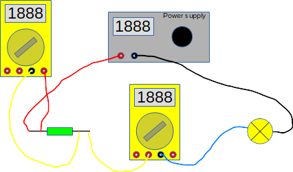
The photo may look a bit confusing, the connections are done this way.
The voltage drop on the ammeter can be ignored for this calibration.
The idea is to move the connection to the multimeter on the resistor, until the voltmeter shows the same as the ammeter. Doing it this way with hooks is not very lasting, it is much better to solder some wires on.
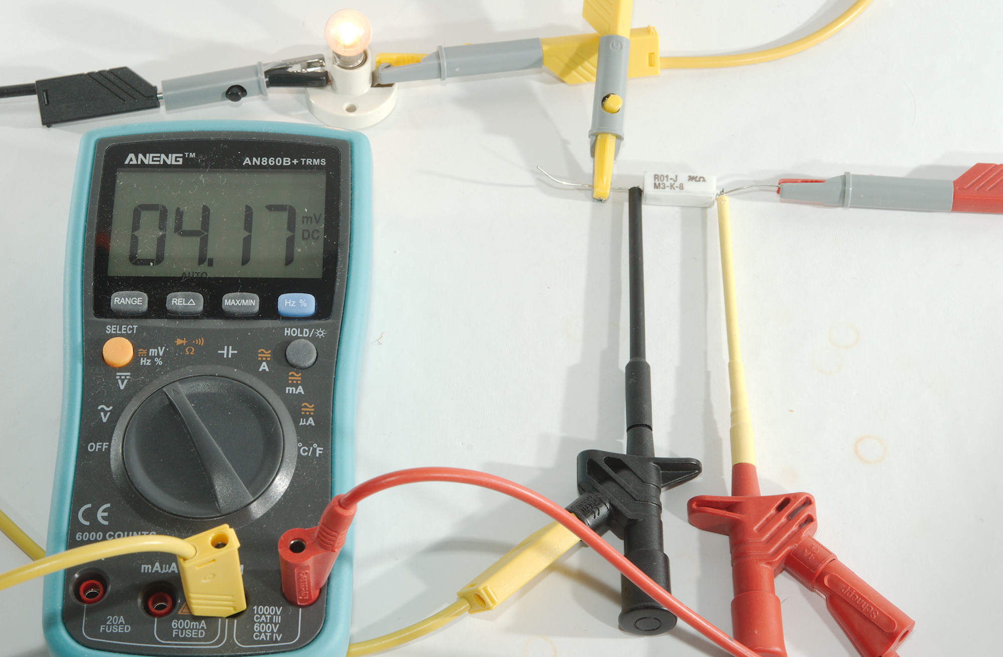
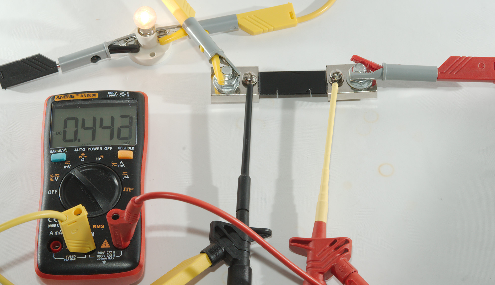
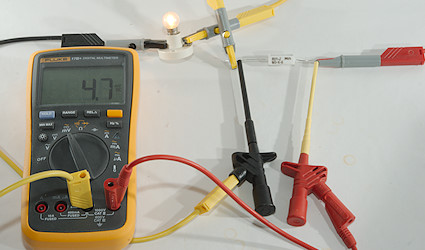
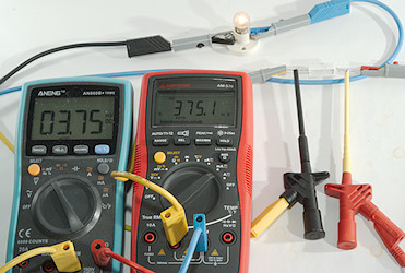
With the calibrated shunt I can measure the precise current and the voltage drop is only 4.4mV on the shunt (More or less, it is 4.7mV from end to end as we saw above).
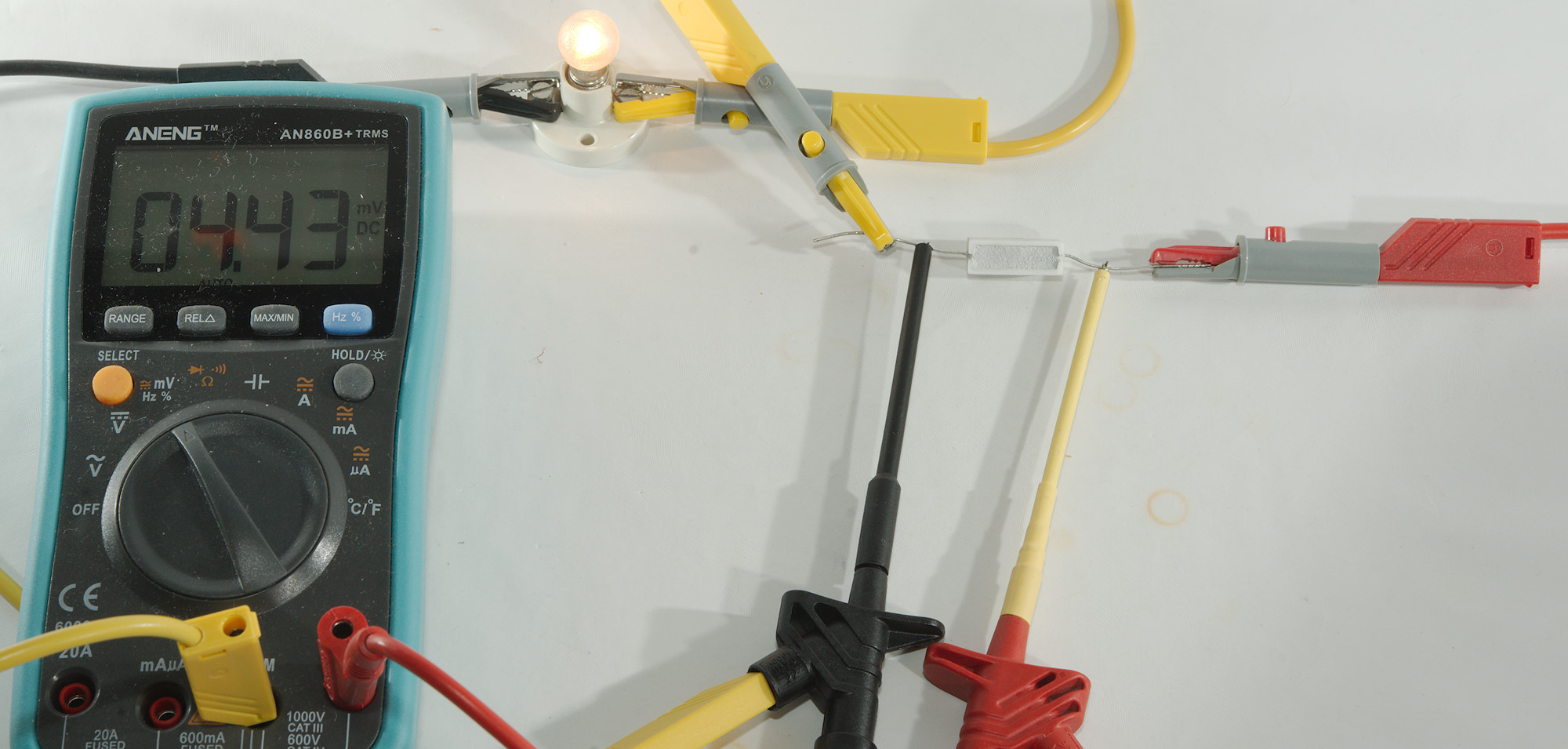
A resistor do not have to be a box, but can be a piece of wire, here I use some copper wire and has selected a length to give 0.001ohm or 1mOhm.
Copper wire is not the best type, because resistance changes fairly much with temperature, instead get Nichrome or Kanthal wire. It has a bit higher resistance and is much more temperature stable.
Calibration is, of course, done the same way as above.
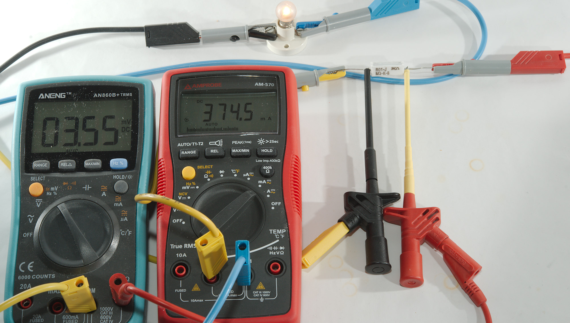
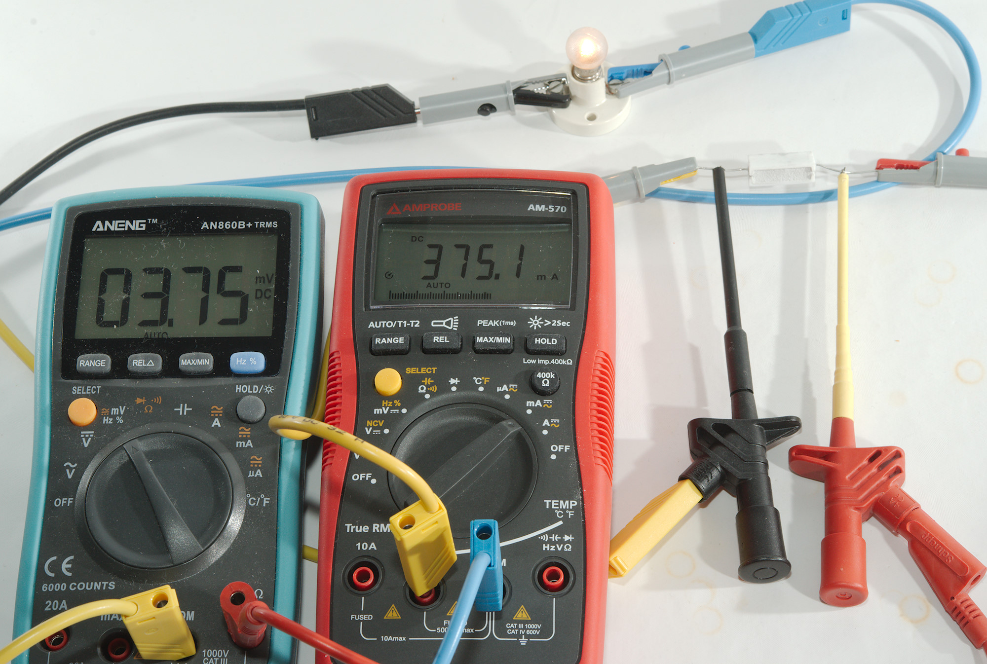
The 1mOhm was a bit low for 0.44A with the meter I used, but it is possible to get meters with even better resolution. This meter here is even fairly cheap (Around $20). This way the voltage drop is also very low at 0.446mV, the other wires will have more voltage drop.
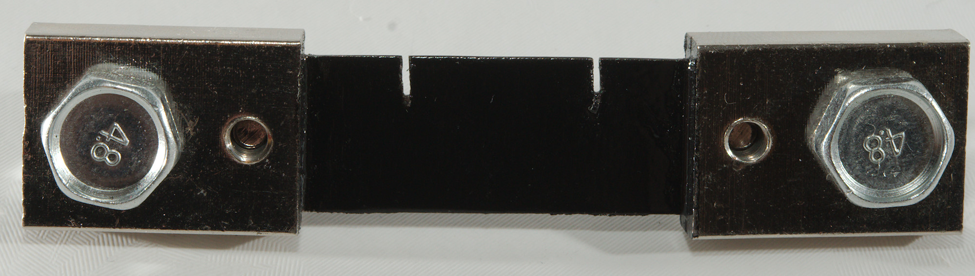
Using a shunt to measure current
It is possible to buy shunts for current measurement, they exist for many different currents and voltages. To avoid doing math when using it, go for these values:
- 50mV & 50A
- 75mV & 75A
- 100mV & 100A this shunt will be physical large, because it has to handle 10 Watt
They are all standard shunt values and they are all 0.001ohm or 1mOhm. Look at the current as a maximum rating, they can always be used at lower currents, if your meter has enough resolution.
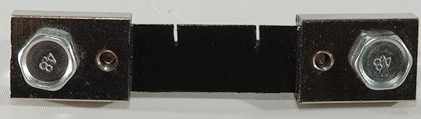
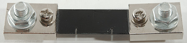
There is nothing on the backside of the shunt.
It works exactly as the resistors above. The small screws are the calibrated point, where the meter is attached. The big screws are for the current.
Measuring pulsing DC current
Modern devices will often pulse current, it can be a microprocessor that only works for a fraction of a second and then wait some time, before doing it again, or it can be a flashlight with PWH or strobe.
How can multimeters be used there?
There are 3 functions that are useful:
- Min/max: As long as the pulses are fairly long (0.3 to 0.5 second or more) the min/max function can show maximum current.
- Peak: This only need about 1/1000 of a second to measure the maximum current.
- Average: This function will calculate a average, i.e. the average current consumption, but it usual requires a fairly expensive meter to get this function.
When using a resistor to measure current, it is possible to build an averaging circuit fairly cheap:
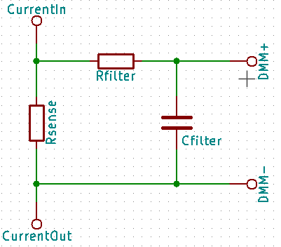
Rsense is the resistor used to measure current from above. Rfilter can be 1Mohm-10Mohm and Cfilter can be 1uF-10uF film or ceramic capacitor (Do not use an electrolytic capacitor). This will slow the meter down and it will show average current. The meter will be about 3xR*C (In Mohm and uF) seconds to show a fairly correct value, the current pulses/spaces must be much shorter to give a stable reading.
The multimeter must have a high input impedance in the mV range for this to work (Many meters have this).
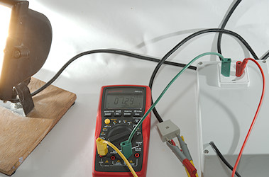
Measuring mains current
All the above works both for AC and DC (With clamp meters DC is optional), but what about mains voltage.

How much current do this lamp use?
When measuring on mains it is best to use a true rms multimeter, modern equipment will give a wrong current on non-true rms multimeters with a few exception: Incandescent lights without any regulation and heaters without any regulation will give correct result on any multimeter.
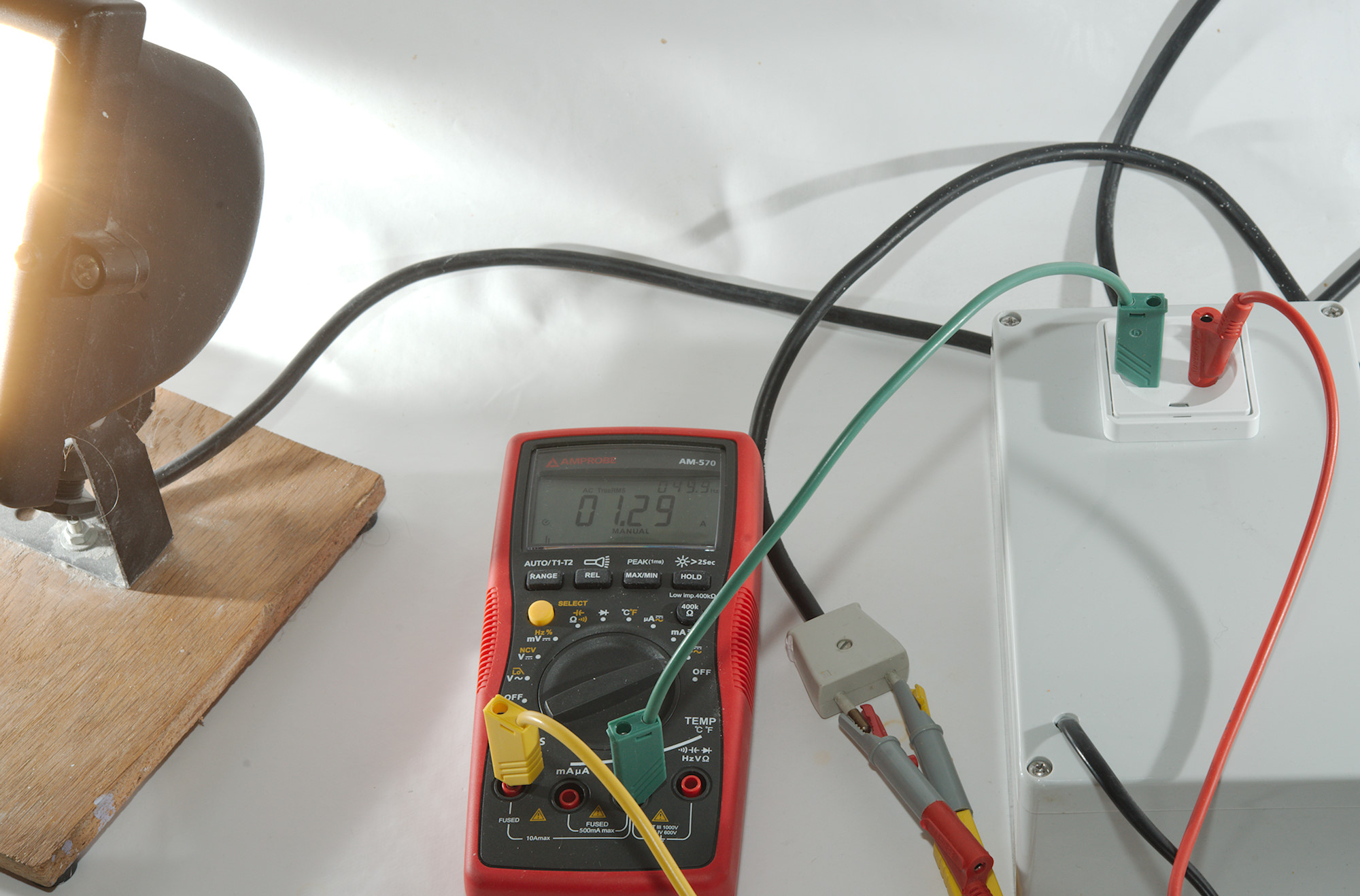
It is easy enough to connect the multimeter, but I will not call it safe and people without isolated alligator clips and banana leads may do something even more unsafe.
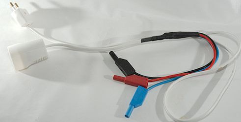
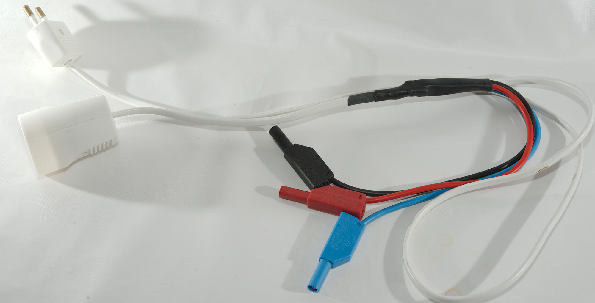
A solution is to make this type of wire with shrouded banana plugs. Mine has both current and voltage connection and connecting it the wrong way will blow the fuse in the multimeter! The cable is made for a specific multimeter (See below) that has black, red and blue terminals.
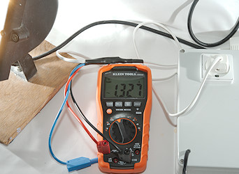
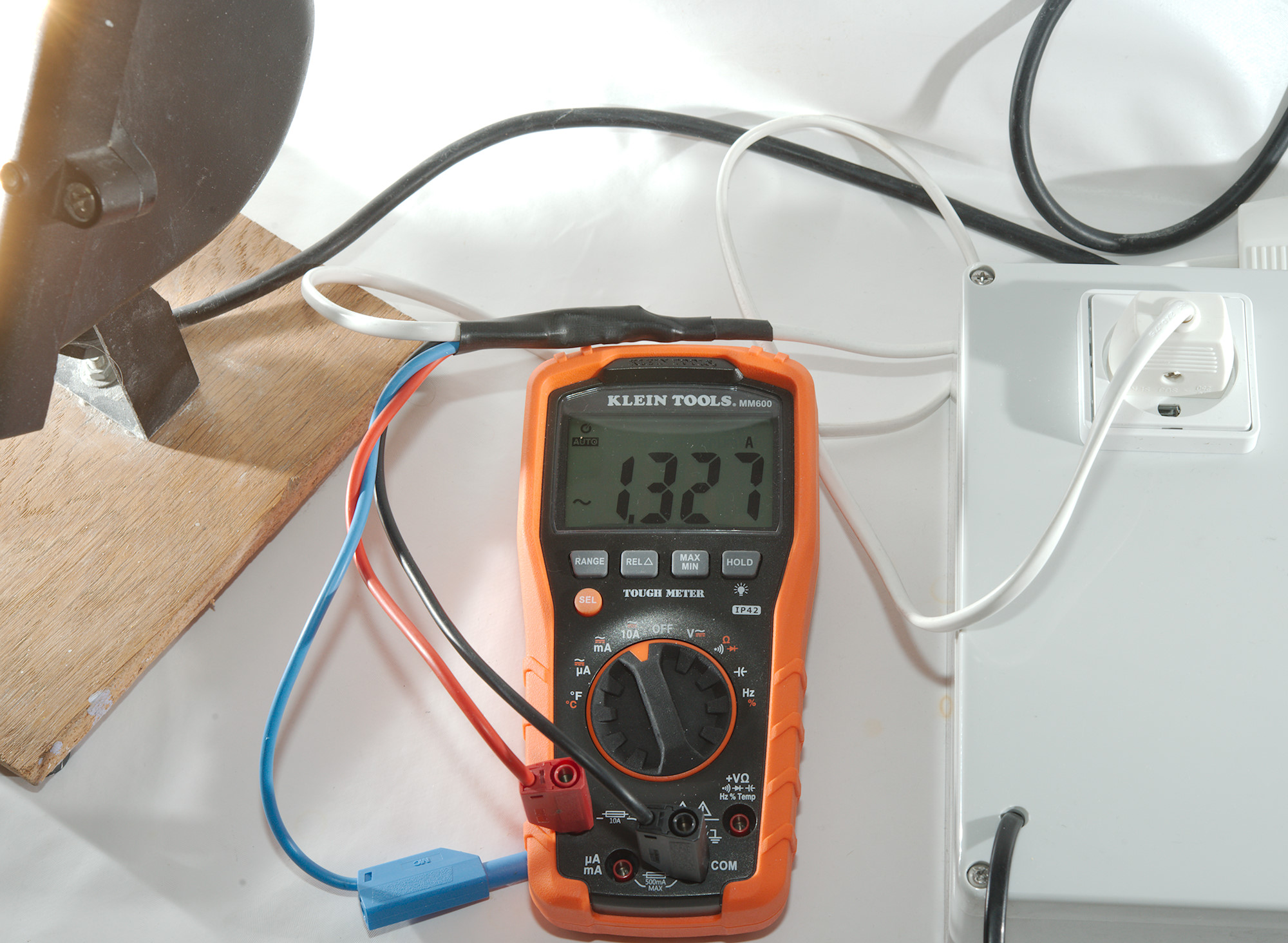
Here it is used with a "random" meter to measure current. For this purpose I will recommend only making it with break-out for current and skip the voltage connection.
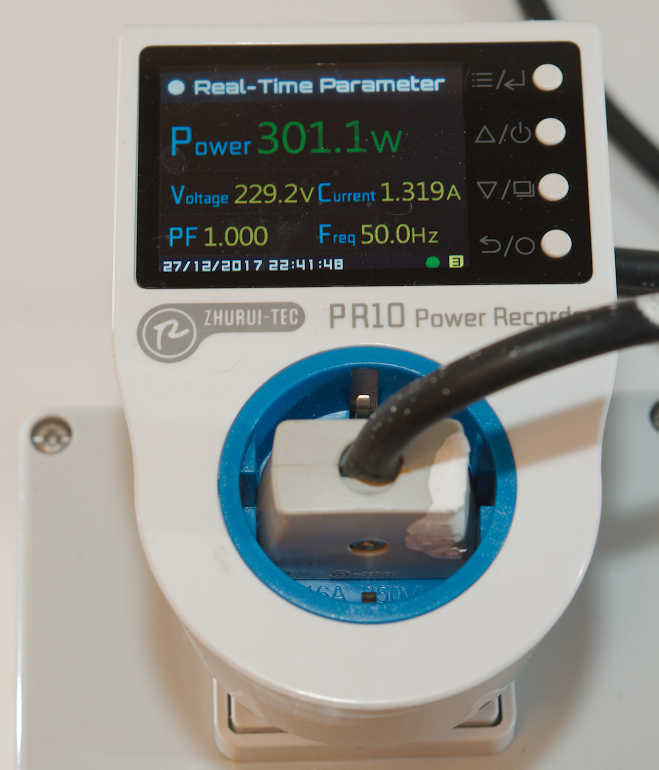
But I did make it for this meter where the color coding matches and it can use all 3 connection at once and will show power in addition to current (Power with AC is not voltage * current, there must be added a power factor to the equation).
In US it is easier, you just get one of these and a clamp meter or clamp for you multimeter.

Here I measure the current.

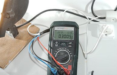
And here I measure 10 times the current, this is very useful for lower current.
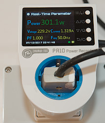
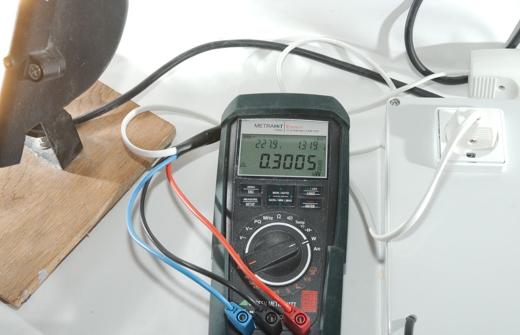
The best way to measure mains current is usual an energy meter like the above, it is true rms, it will measure power correct and it is much safe than the above.
What to look for on a Clamp meter
There is two or 3 details to check when buying a clamp meter:
- It can measure DC
- It can measure low enough current for your purpose.
- For using on mains: It can measure true-rms

This meter has all the keywords, a 2A range, AC/DC marking and "True RMS" marking.

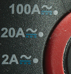
It can do AC/DC and it has "True RMS", but what about low current? This clamp has a resolution of 10mA, this is good for a clamp that goes up to 1000A, but a bit high for some purposes.
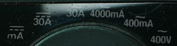

Another clamp, with a mA range, this sound good, but is it 400.0mA or 4000mA? It is 4000mA!
It is also marked with AC/DC and True RMS, i.e. fine for just about everything.
What to look for on a multimeter
Check for:
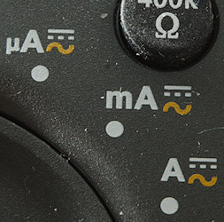
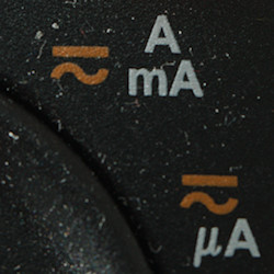
- 3 current ranges on the range switch: uA, mA and A (Two can be at the same position).
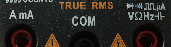
- Two current input terminals, one for A and one for mA uA
- No current measurement on the volt input (This is safer).
- 6 current ranges, check specifications: 2xuA, 2xmA and 2xA ranges
- Low burden voltage (Typical worst case is 2ohm in high mA range, but a few meters are worse than that, like the Amprobe I use above.
- Resolution in mV range, best is 0.001mV, worst is 1mV. This is only used when using external resistors to measure current.

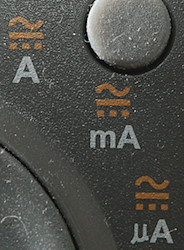
Both True RMS and 3 positions on the range switch, but it is not possible to see if it is missing the A range (This meter have it).

Exactly the same on this meter, but it is missing the A range.
This meter has both mA and A on the same position, this is perfectly fine, but they are also on the same terminal and that is very suspicious and the uA terminal is shared with the voltage input, that is problematic. The meter has one mA range and one A range, there is also two uA ranges, but a hole of two mA ranges (One of them is usual the high uA range). This meter is a very useful for current measurements, but it cannot handle all ranges and need another meter as supplement.
Conclusion
With clamps it is easy to measure current. It is not necessary to break the circuit and there will not be a voltage drop, only requirement is access to a single wire, not a cable with current going both ways. The precision is good enough for most work, but not precise.
With DMM's it is necessary to break the circuit and add the DMM to the circuit. This will add some resistance, that may or may not be significant.
With DMM's it is also possible to use an external resistor, either a normal resistor, a wire or a dedicated shunt. This can reduce the resistance and extend the ranges supported by the multimeter.
Measuring mains current is a bit unsafe, for most purposes a dedicated energy meter is much better.
Notes
Selection table with tested multimeters
Building a high current adapter
More about multimeters:
Multimeters and thermocouples
Tolerance specifications for multimeters,