Multimeters and thermocouples
Many multimeters includes a temperature sensor, usual of a type called a thermocouple, in this article I will look on how this temperature sensor works and a few pitfalls when using it.
Contents
Theory
Specifications
A look at some thermocouples
Internal temperature sensor and cold junction compensation
Extending thermocouple wires
Conclusion
Notes
Theory
When dissimilar conductors are connected they will generate some voltage, depending on the temperature, this can be used to measure temperature differences with. Thermocouples are made of conductors with well-defined voltage vs. temperature curves. There are a couple different type of conductor combinations used for thermocouples, the most common combinations is assigned a letter. The one typically used with multimeters is assigned the letter K. This means it is called a "Type K thermocouple".
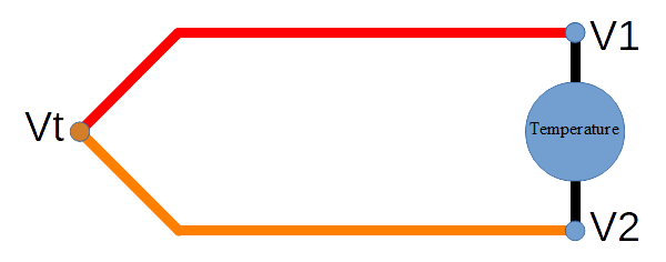
A thermocouple circuit. The red and orange are the two thermocouple conductors and black is the wiring in the meter, (i.e. the copper on the circuit board). All 3 connections (Vt, V1 and V2) generate a voltage, but V1 and V2 is just besides each other on the multimeter and have the same temperature (Hopefully), this means they will generate equal voltage, but with opposite sign and thus compensate each other out. The meter will show the temperature difference between itself and Vt.
I have skipped a couple of different conductor junctions, like the connectors in the multimeter are seldom of copper. All these junctions will usual cancel each other out fairly well.
But most people do not want a temperature difference (The probe is 10°C hotter than the multimeter), but the absolute temperature (The probe is 35°C).
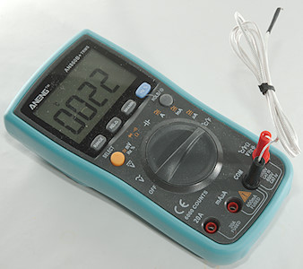
This is solved by putting another temperature sensor inside the multimeter. Here I have shorted the thermocouple input and gets the internal temperature sensor. This is also called "Cold junction compensation".
Some multimeters will automatic switch to the internal temperature sensor when no thermocouple is connected, but shorting the input will always show it.
Specifications
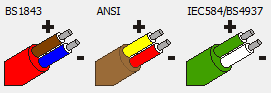
There are some standard specifications for each type thermocouple, that includes voltage vs. temperature, temperature range and under what conditions, but also connectors and colors.
The K type conductors can be used from -270°C to +1372°C, but the isolation on the probes can usual not handle that temperature range. The two conductors are made of chromel and alumel alloys.
The best precision class has a tolerance of ±1.5°C and the second class has ±2.5°C in the -40°C to around 350°C temperature range. According to the ANSI standard it must use a brown cable with yellow connector and red/yellow wires in the cable (There is IEC and BS standard with different colors).
The voltage is around 41uV/K and nearly linear, except at the extremes (Many multimeters cannot show very low temperatures correctly due to that).
The precision do not depends on wire thickness or length, but on how precise the alloy is, the wire thickness only has something to do with how robust the thermocouple is.
The isolation material will often limit the temperature range of the thermocouple.
Some other thermocouples use the letters: B, E, J, N, R, S, T
When using thermocouples, the thermocouple precision and the meters precision must be added together.
A look at some thermocouples
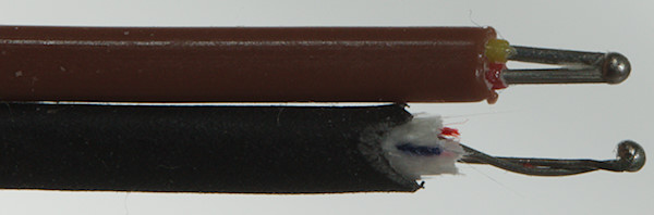
Lets just take a look at the thermocouple junction first. The two conductors are welded together in a very small junction and the temperature is measured exactly at that junction. The first one is a good quality thermocouple from Fluke, the second one is a cheap one. They will both work, how precise depends on the purity of the alloys used.
This small junction is easy to place in many different location and it is fast to measure the temperature.
When placing the thermocouple it is usual a good idea to also let a little bit of the wire be touching the object, to prevent the wire to drain heat from the junction.
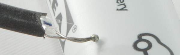
Not very good placement of thermocouple, only a little bit of the junction is touching.
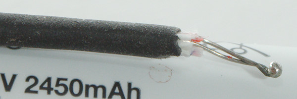
Better placement, junction and a bit of the wires behind the junction is touching.
Add some sticky tape or a rubber band to keep it in place and pressed against the object.
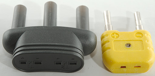
There is usual 3 different thermocouple connectors used with multimeters.
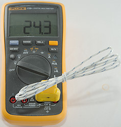
This model has a dual banana plug connector that fits into most multimeters.
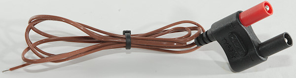
The Fluke version of the above, using red plastic for one of the plugs makes it easier to put it in the right way.
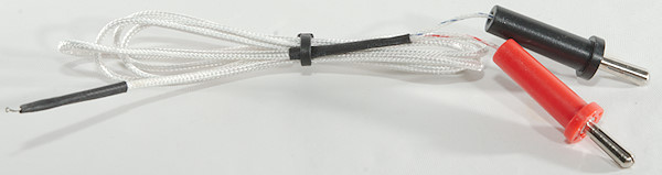
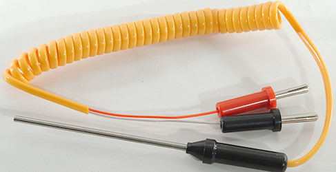
The really cheap thermocouples just have two banana plugs.
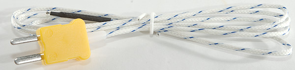
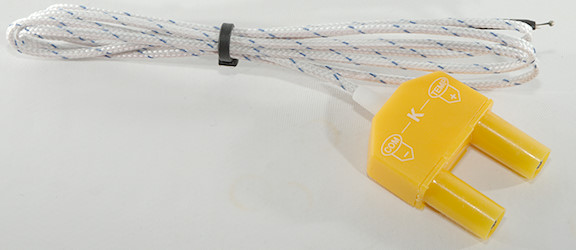
This is a "standard thermocouple plug", in some cases there can be an advantage with these. I will get back to that later. These plugs are polarized and cannot be plugged in the wrong way.
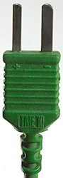
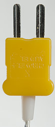
A closer look at the thermocouple plugs.
The first 3 plugs directly into the multimeter.
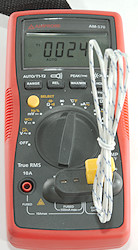
The last model usual requires an adapter. They are supplied with the multimeter if the supplied thermocouple requires it, but can be bought cheaply on Ebay.
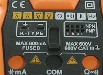
A few meters do have a thermocouple socket. This is usual a bad idea due to safety, on this meter it is solved by a shutter that only allows ordinary probes or thermocouple, you cannot connect both at the same time.
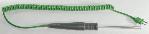
The standard thermocouple plug is used on a wide variety of thermocouple probes, here is one to measure surface temperature.
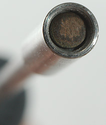
I have also seen a encapsulate cheap probe for multimeters, it is fine when you want to stick the probe into something, but is not very good at measuring surface temperature.
Internal temperature sensor and cold junction compensation
This is the typical design in a multimeter thermocouple, the chromel and alumel alloys are terminated in the banana plugs, that is then connected to the multimeter plugs. This means the temperature measured is from the banana plug to the thermocouple junction. The internal temperature sensor that is used to compensate for ambient temperature is placed somewhere inside the multimeter.
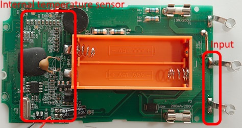
In this meter there is no temperature sensor near the input terminals, this means it must be at the other end of the multimeter and probably inside the multimeter IC.
Moving the temperature sensor close to the input terminals will improve the tracking of the terminals temperature and reduce the error due to fast changing temperatures.
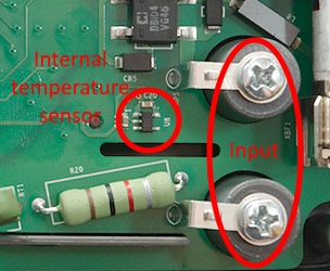
On this Fluke the temperature sensor is fairly close to the input terminals, but not in contact with them.
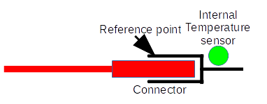
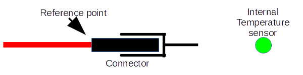
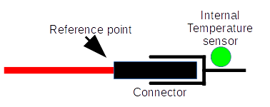
When using the thermocouple connectors the two spades are made of thermocouple conductor (This is probably not the case on cheap connectors), this means that the reference point is moved inside the connector and a good meter designed for thermocouples will have the internal temperature sensor mounted directly on the connector with good thermal contact (This is not the case with cheap meters), i.e. it will track the junction temperature fast and precise, normal multimeters cannot do that.
This also means that using a thermocouple connector and adapter for a multimeter may be slightly worse than using a thermocouple with banana plugs, because the reference point gets further away from the multimeter and the internal temperature sensor.
What does the above means?
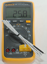
- Using the multimeter on the bench to measure temperature is usual fairly precise, because the multimeter have been there for hours and will have the same temperature from connectors to internal temperature sensor and the thermocouple connector will also have this temperature.
- Taking the multimeter out in hot/cold weather will introduce a large error fairly fast when the connector heat/cool due to the weather, but the internal temperature sensor changes temperature much slower.
- To get precise measurements, always give the multimeter and thermocouple connector time to reach ambient temperature (2 hours is fine).
I will just repeat this, it shows what temperature the multimeter believe there is and can be used to check if the multimeter has reached ambient temperature.
Extending thermocouple wires
To solve the above, we could extend the wires and let the multimeter stay indoors, at least as long as the temperature that we want to measure is close to the house.
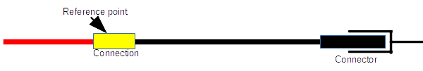
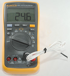
A piece of copper wire and it is extended, but the temperature is measured from the connection between the thermocouple wire and the copper wire. This is not very useful.
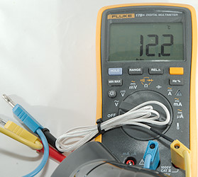
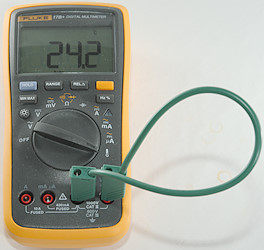
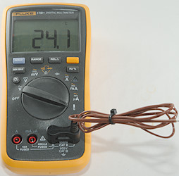
A couple of seconds with a hairdryer and my room got about 12°C cooler. I am blowing on the connection between the yellow/blue wires and the thermocouple and because this is the reference point the meter will see negative temperature from the thermocouple. This is then added to the internal temperature sensor and will show a lower temperature.
I.e. thermocouple is 24°C, but reference junction is 36°C due to me heating it, the thermocouple will report -12°C to the meter. This is then added to the internal temperature of 24°C and gives a reading of 12°C.
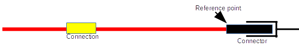
It is possible to buy special thermocouple extension cables, they are made of the same conductors as thermocouples. That way the reference point can be kept at the multimeter and not at a connection somewhere else.
There exist two types of extension cables, real thermocouple wires and some cheaper wires that are fairly precise around ordinary temperatures.
Conclusion
Multimeters and thermocouple are very useful for temperature measurement. The sensors are easy to put just about everywhere and there are sold sensors for more special applications.
But it is not a precise measurement and it can only measure relative temperature, there is always a second temperature sensor to compensate for ambient temperature (or rather temperature of the thermocouple connection). On specialized thermocouple meters that sensor may be on the connector.
Notes
For precise and absolute temperature measurement a PT100 sensor (Also called RTD) is used, Fluke has one (5627A) that is ±0.046°C at 0°C for about $900. Benchmeters can usual handle them.
Multimeter (DMM) information and reviews
More about multimeters:
Multimeters and current measurements
Tolerance specifications for multimeters