Tolerance specifications for multimeters
Usual a multimeter manual includes some specifications on how precise the meter is, in this article I will look on how to read these specifications.
Contents
Digits and counts
When tolerances do not apply
Simple tolerances
Examples on simple tolerances
AC tolerances
Examples on AC specifications
Ohm and capacitance
Frequency
Temperature
Extra functions: Low-Z, Peak, LPF, etc.
Environment
High precision meters
Calibration
Conclusion
Notes
Digits and counts
Meters are often specified with digits or counts, this do not directly say anything about the precision, but it is usual assumed that a meter with more digits has better precision (This is not always the case).
Lets first look at counts, this is how many different values the display can show, i.e. a meter that can show all values from 0000 to 1999 has 2000 count, from 0000 to 3999 is 4000 count. If the meter can show from 0000 to 4000 is is also specified as 4000 count, even though the correct value is 4001. This rounding is also used for higher value, even 6200 or 6600 as maximum reading may be specified as 6000 count (In my reviews I do not round that much). Sometimes meters have different maximum in different ranges, frequency and sometimes capacity may go to 9999, even if voltage only go to 4000, this do not affect the specification. Count is for voltage and current.
Number of digits is, of course, the number of digits, but what about the fractional digit? This praxsis started with some of the early multimeters, they had a reading from 000 to 1999, the first 1 was only two segment on the display and could not show a full digit, only a 1 or nothing. This made it dififcult to call it a 4 digit meter and 3 digit did not describe the meter correctly either, thus the ½ digit was born and they where described as 3½ digit meters. Some years later manufacturers made better meters that could show 3000, 4000, 5000 or even 6000 on the display, this time with a full digit, but it would still be misleading to call it a 4 digit meter, when it cannot show up to 9 in the first digit and ½ was already used to describe a 1 as first digit. For this reason 3/4 or 5/6 fractions was used to describe these meters, but there is not any fixed standard for this.
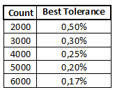
The number of digits/count puts a limit on how good the precision can be on a specific meter. The above table is based on the best precision that can be achieved at 1/10 of full range, i.e. just after a change to next higher range (Like 199.9 > 200)
Because the tolerance specification is a combination of two numbers it is possible to "cheat" on the percent specification, by increasing the second value.
When tolerances do not apply
Tolerances specify how large a error there can be on the display value, compared to the value on the terminals of the meter. Let me start with 3 examples that is not covered by tolerances:
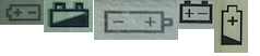
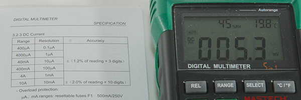
When battery is near empty, some multimeters will show correct value until they turn off, other may shows very wrong values.
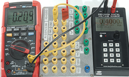
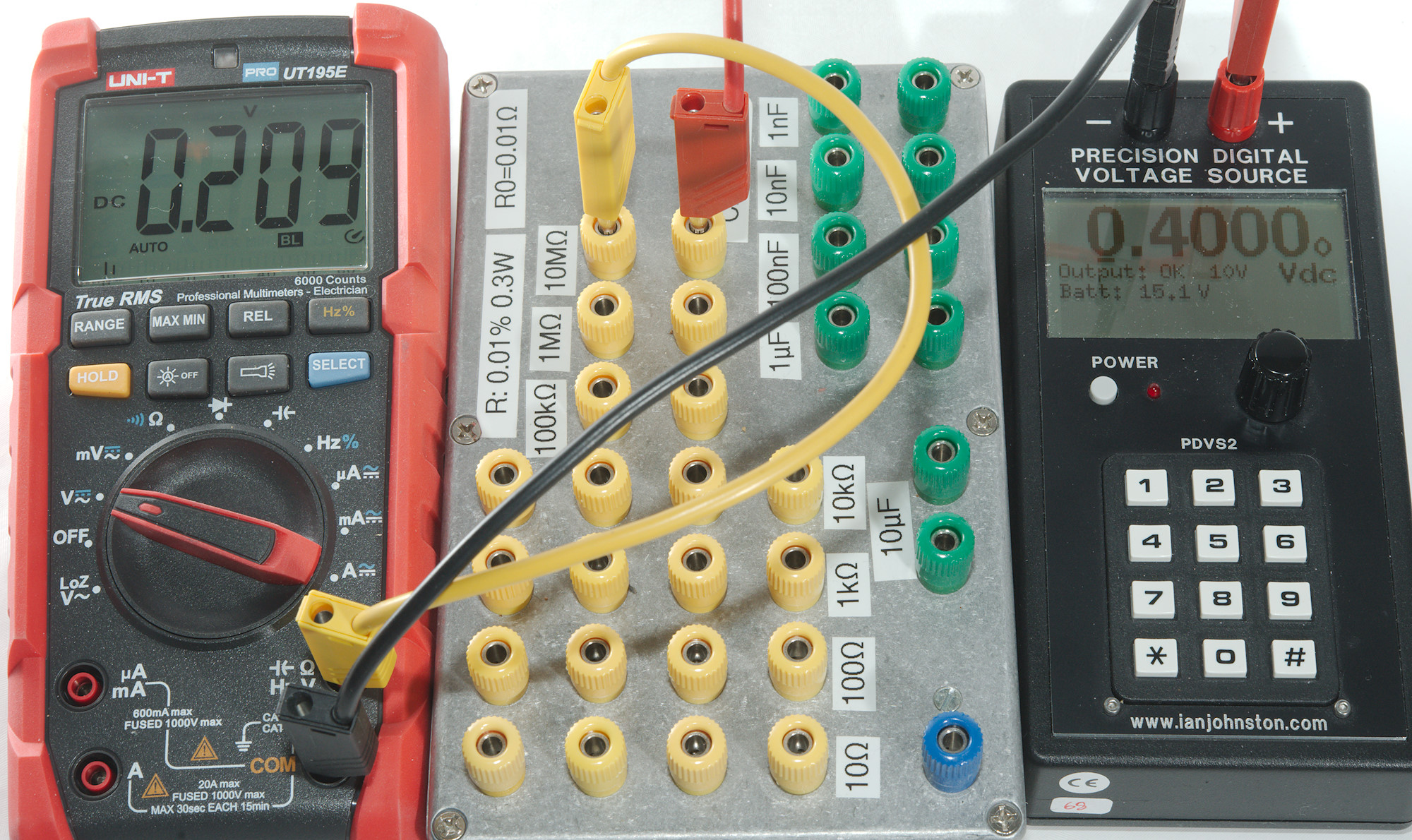
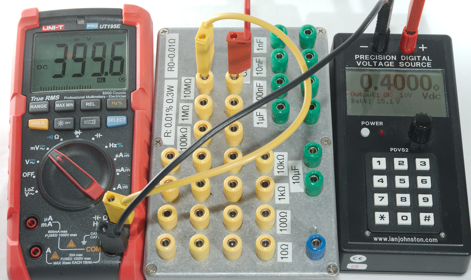
The reference is delivering 0.4V, but the meter only shows 0.2V, this is because the meter is measuring at a high impedance location and works as a voltage divider together with the 10Mohm resistor there is in series with the reference.
The meter is probably 11Mohm, i.e. the value the meter see is: 0.4V*11Mohm/(11Mohm+10Mohm) -> 0.2095V
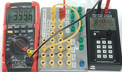
This meter has a high input impedance mode in the mV range (Most meters have), this fixes the problem (At least when hands are keep away from the wires, due to the high impedance they are fairly sensitive).
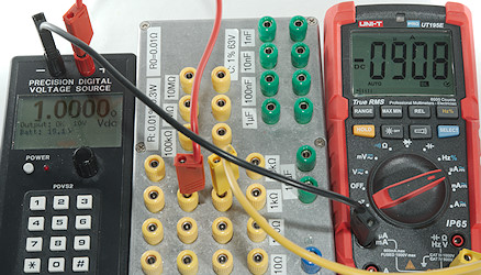
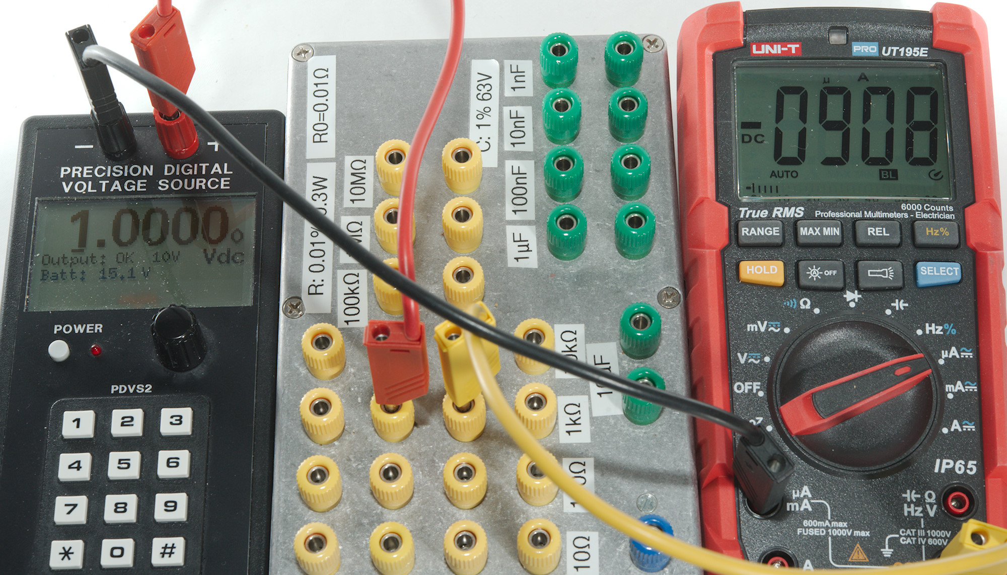
Here I am sending 1V through a 1kOhm resistor (Both are very precise), i.e. the current must be 1mA or 1000uA, but the meter shows 908uA. Is the meter faulty? The answer is, of course, no, but current measurements will affect the circuit and the meter has an internal 100ohm resistor and 1ohm fuse (The last two values are the common values for many multimeters) it measures the voltage across to calculate the current. This means the current is 1V/(1000ohm+100ohm+1ohm) -> 908uA, the meter is within its tolerances!
Simple tolerances
The specification is usual in the form of "number1% ± number2". Number1 is tolerance on the actual value in the display and number2 is a static error. This means if the you have the specifications "0.5% ± 2" and the display shows 512 the tolerance is 512*0.5% -> 2.56 -> 3 from the 0.5% and 2 more from the ± 2 for a total of 5. This means the real value will be somewhere from 512-5 -> 507 to 512+5 -> 517
When doing these calculations any decimal point in the displayed value is best ignored during calculations and first used again on the final result. I.e. if the display shows 5.12, use the same calculations as above and when you have the final result add the point again for 5.07 to 5.17.
This type of tolerances is used for nearly all ranges on a multimeter, but for some ranges there may be other factors and more specifications, I will cover them in the next chapters.
To make percent calculations a bit easier I have made a table. Use the value on the display and percent closets to the meters rating and you have a usable estimate:
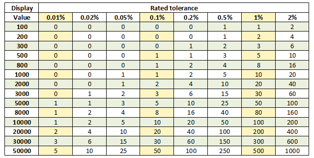
For the above calculation look in the 0.5% column and 500 row and you find the 3, the 2 must still be added for the total tolerance.
Examples on simple tolerances
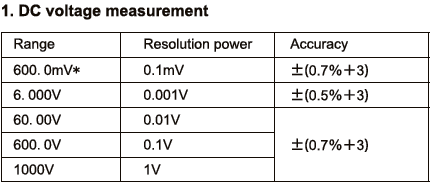
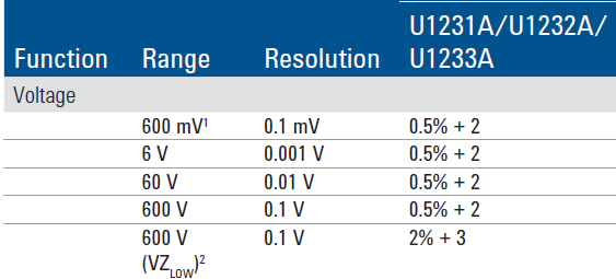
This is a typical simple tolerance specification.
A few practical examples:
- Display 2.000V in 6.000V range: The 0.5% is 10 and then the +3 for a total of 13, i.e. the real value is somewhere between 2.000-0.013 to 2.000+0.013 -> 1.987 to 2.013 volt.
- Display 2.00V in 60.00V range: The 0.7% is 1.4 and then the +3 for a total of 4 (rounded down), i.e. the real value is somewhere between 2.00-0.04 to 2.00+0.04 -> 1.96 to 2.04 volt.
Notice how much worse the precision got when using too high range. In some situations this difference is very significant, let compare two meters both with "0.5% + 3" specification, but one 4000 count and the other 6000 count, both used to measure 4.1V:
- Display 4.10V in 40.00V range: The 0.5% is 2 and then the +3 for a total of 5, i.e. the real value is somewhere between 4.10-0.05 to 4.10+0.05 -> 4.05 to 4.15 volt.
- Display 4.100V in 6.000V range: The 0.5% is 21 and then the +3 for a total of 24, i.e. the real value is somewhere between 4.100-0.024 to 4.100+0.024 -> 4.076 to 4.124 volt.
That change from 4000 to 6000 count improved the precision significantly, with 4000 count the result was within ±0.05 volt, with 6000 count within ±0.024 volt or about half the tolerance. This big improvement will, of course, only exist in the gap between the maximum readings of the two meters.
AC tolerances
The AC voltage and current ranges will also use the above tolerances, but it do not tell the full story. The problem is that AC is not just AC.
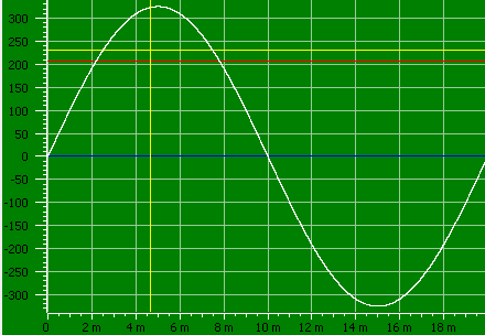
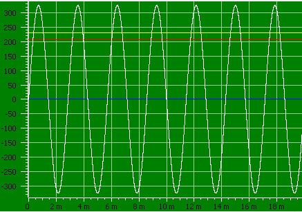
This curve shows a normal AC voltage at 230VAC and 50Hz, i.e. mains voltage in Europe. This will usual work, but there is one limit and that is low voltage. It is common for AC ranges to have a minimum input value of 5% to 10% of the range, i.e. a 1000 volt range may not show correct below 50 or 100 volt (In the meters I have checked the error is not that bad).
If the display has a small value on it with shorted probes, it is usual a bad idea to use the REL button to remove that value. Because it is outside the valid range, the effect on the valid range is unspecified and it may increase errors instead of reduce them.
But not all measurements may be on mains voltage, sometimes measurements are done at other frequencies. The meter may have a single specification saying it works from "50 to 400Hz" or it may have a couple of specifications depending on frequency range with increasing tolerance when getting away from 50/60 Hz. This is very relevant when working with audio where frequencies up to 20kHz can be used (Only some meters support this).
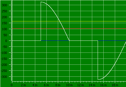
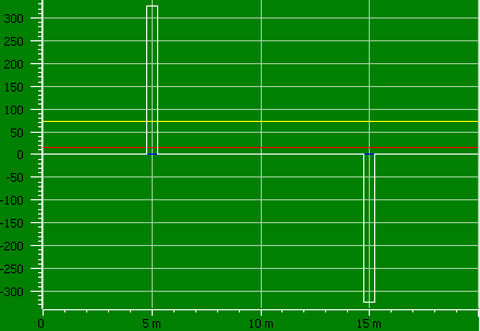
If somebody is using a dimmer it may look this way after the dimmer, this is 162.7 volt rms, but not all meters will show that.
First requirement is that the meter is "True-rms", but that is not enough, it must have bandwidth to handle the curve and the also be able to handle the peak voltage, before it can show the correct value.
Without True-rms the display will show 115.0 volt or less due to other limitations.
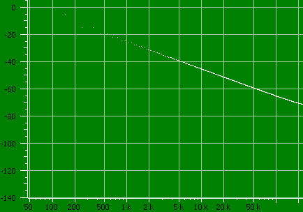
Any non-sinusoidal waveform will contain higher frequencies and it is possible to draw a curve of them. In the above curve it shows the level at different frequencies. I have listed the first few in the table below:
1×Fo (50 Hz):1 0 dB 136 V RMS -32.5 °
3×Fo (150 Hz):537m -5.4 dB 73.2 V RMS 90 °
5×Fo (250 Hz):179m -14.9 dB 24.4 V RMS -89.9 °
7×Fo (350 Hz):179m -14.9 dB 24.4 V RMS 90.1 °
9×Fo (450 Hz):107m -19.4 dB 14.6 V RMS -89.9 °
Most of the energy is at 50Hz for this curve, but some curve shapes may have a significant part of the energy in the harmonics (Any frequency that is specified as nx50Hz in the above, except 1x50Hz).
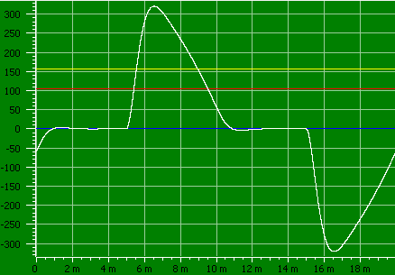
A meter with a 400Hz bandwidth would see something like this for the above curve, it has 157.8V rms.
The other factor is called "Crest factor" and specifies how large the peak voltage is compared to the rms voltage. For a normal sinus it is 1.4, for the above curve it is 2.0, this means the meter must be able to handle twice the displayed voltage, this is not a problem for mains voltages.
Usual meters are rated for a Crest factor of 2 to 3 (Except at the top of the highest AC range) and some high end meters may go up to 10 on the lower part of the range.
The factor 3 means the meter can handle 300 volt peak when displaying 100 volt and 10 means 1000 volt peak while displaying 100 volt.
The specifications may also list extra tolerances for high crest factors.
This curve is really hard to measure correctly.
It has a high crest factor (4.5), requires good bandwidth of the multimeter and requires true-rms.
To summarize:
AC specifications adds true rms or not, frequency ranges and crest factor to the basic specifications. This usual includes wider tolerances for anything not 50-60Hz and sinusoidal.
Examples on AC specifications
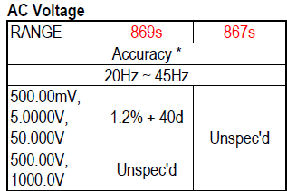
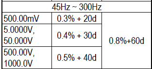
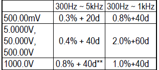
Lets calculate tolerance for a few readings on the 869s meter:
- 20.000 volt @ 50Hz in 50.000V range: 0.4% is 80 and then the 30d for a total of 110, i.e. real value is somewhere between 20.000-0.110 to 20.000+0.110 -> 19.890 to 20.110 volt.
- 20.000 volt @ 50Hz in 500.00V range: That is 4% of range and the tolerance is unspecified.
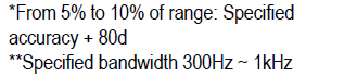
- 30.00 volt @ 50Hz in 500.00V range: 0.4% is 15 and then the 40d and additional 80d because value is below 10% of range for a total of 135, i.e. real value is somewhere between 30.00-1.35 to 30.00+1.35 -> 28.65 to 31.35
- 30.000 volt @ 50Hz in 50.000V range: 0.4% is 120 and then the 30d for a total of 150, i.e. real value is somewhere between 30.000-0.150 to 30.000+0.150 -> 29.850 to 30.150
- 30.000 volt @ 1000Hz in 50.000V range: 0.4% is 120 and then the 40d for a total of 160, i.e. real value is somewhere between 30.000-0.160 to 30.000+0.160 -> 29.840 to 30.160
As can be seen the precision is best when using the correct range, the "± number2" can easily spoil a good percent value at lower readings in a range.
Ohm and capacitance
These ranges has some special conditions at both the high and low end of the ranges and also in the range for capacitors:
- In ohm the lower values are limited in accuracy due to cable and contact resistance. The cable resistance can be eliminated by using the REL button on the meter (if it has one), but the contact resistance can only be fixed by making good contact. This resistance may not always be included in the specified tolerances (High end bench meters has a 4 terminal ohm mode that will elimate wire and connection resistance).
- When measuring higher values, watch out for your fingers (The resistance between fingers on your two hands can easily be below 100k), this error is never included in the specification, but can easily occur.
- High megaohm values are very sensitive to noise and moisture, that includes moisture inside the multimeter. This may be partially included in the specifications.
- Low capacity values are affect by tolerances inside the meter and by the cable. This can be up to 10's of pF in error with unconnected probes. Use the REL button to eliminate this error. Tolerances for the low capacity range usual assumes that REL has been used. It is a good idea to use short test cables or have the cables and hands placed the same way when using REL and when measuring.
- High capacity values, this will be electrolytic capacitors and they have leak current that may affect the precision or even prevent measuring them.
- Capacitors are made many different ways and not all methods has a stable capacitance, many capacitors change value with frequency (Dedicated capacitance meters can measure at different frequencies), there are also some capacitors that change value with voltage. This means the value measured by the multimeter may not be the same value the capacitor has in the circuit under actual operating conditions.

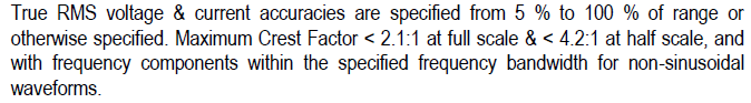
A typical note in multimeter specifications.
Frequency
I do not use much space on precision of frequency displays, this is because multimeters usual has a crystal in them and this means the frequency precision will be about as precise as the number of digits on the display, usual within a few counts.
The limits are too low signal levels or a frequency outside the valid range, both can give wrong readings.
Some old multimeters do not have a real frequency counter, but converts the frequency to a voltage and then measures the voltage, this will not be very precise!
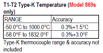
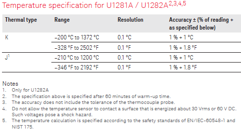
Temperature
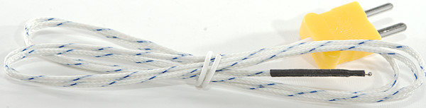
Many meters can use a thermocouple to measure temperature, the tolerance specifications for the thermocoupler is only for the meter, not for the actual thermocoupler, even if it is supplied with the meter. This tolerance also assumes that the meter and thermocoupler connection to the meter is at the same stable temperature. This means when the meter is moved to a different temperature, it need some time to stabilize, before it is within tolerances.
More about thermocouplers
Extra functions: Low-Z, Peak, LPF, etc.
These functions will not have same precision as the main function, i.e. when selecting Low-Z it is not the general AC tolerance that is valid, usual there will be another specifications with worse tolerance for this.
Low-Z is a special low impedance mode, for some reason it will affect precision to select it. It will often force the meter to the high voltage range, making the precision worse at low ranges (Sometimes it will not even work at low voltages).
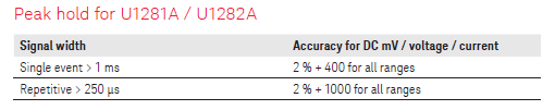
Peak tries to capture the highest/lowest voltage, this means it has to be fast. This also means it will not use the same circuit as for the normal measurements, but a circuit that is optimized for fast capturing of values. This will not be as precise as normal voltage measurements.
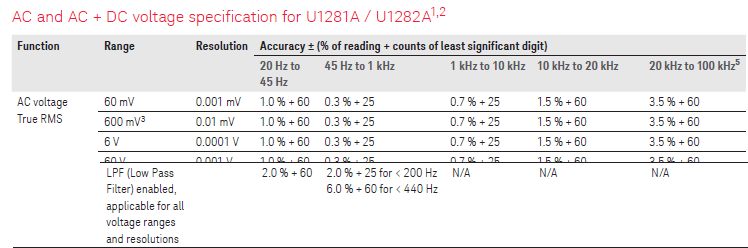
A low pass filter (LPF/VFD) function will remove higher frequencies, but it affect all frequencies.
Environment
All the above specifications is valid at around 25°C (Range is usual 18°C to 28°C) in not too moist conditions, outside that temperature range or at high humidity the meter will not be as precise, i.e. neither in very hot location or cold location will it be as precise.
For better meters the specifications may include some extra percent to add to the tolerance, depending on temperature. It can be something like "0.1*specified_tolerance/°C" outside the 18°C to 28°C range and may be a common specification for all ranges. That would double the tolerance when 10°C below 18°C or above 28°C
Examples from a datasheets:
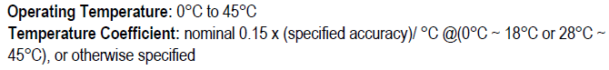

There is also limits to how far the meter can and must be used outside its best operating temperature. Outside these limits may damage the calibration permanently.
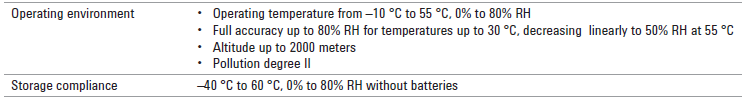
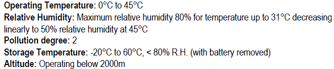
Another meter:
High precision meters
Specifications for meters with high precision may be slightly different for a couple of reasons.
- When a meter has 0.001% precision, it may be nicer to write it in PPM (Parts per Million, one PPM is 0.0001%), this changes the 0.001% to 10ppm, it is still the same tolerance, just easier to read.
- Some meters has a variable number of digits, i.e. at the press of a button it can display: 5.00V, 5.000V, 5.0000V, this makes the "± number2" specification a bit tricky, because ±2 may be ±20 when adding more digits. The solution to this is to specify it as a percent of full range, i.e. a meter with a 5000 and 50000 reading may specify it as ±0.06% of full scale, this means 5000*0.06% -> ±3 in 5000 range and 50000*0.06% -> ±30 in 50000 range. Again the value may be specified in PPM instead of % (See above).
- With better precision there is usual more factors that will affect the precision, this means that the specifications will list more tolerances and additions to tolerances.
- With very high precision meters, the tolerance may be specified as time after calibration. There may be tolerances for up to 24 hours, a few months (90 days), a year and in some cases two years. These tolerances are worst case and meters will usual be considerable better, but for important measurements you cannot depend on that.
- To reach the full precision this type of meters may need some time to warm up.
Calibration
Meters specify a calibration interval (Typically a year), this do not mean that they go out of calibration after that time, it means that to be sure the reading is correct the meter must be verified after that time interval.
The above picture is misleading, a calibration do not necessary including any adjustment to the meter, it is only a verification. If it do not pass the verification it must go to service to be adjusted and everything it has been used for since last calibration may need to be checked again.
Note: With modern electronically adjusted meters, it is possible to do the adjustment during calibration, but it may not be done to keep better track of the drift on the meter.
Conclusion
Do never expect a multimeter to show exactly the correct value, some meters may show the correct value (within the digits they have), some of the time, but the specified tolerances are there for a reason. Some of the reasons are calibration precision on the factory, uncalibrated ranges (Instead they depend on precision parts) and changes over time. The last part (Changes over time) will depend on how the meter is used and stored, temperature variations will usual increase the rate of change (i.e. how fast the meter go out of calibration).
Notes
The button I call REL can also be called ZERO or NULL, depending on meter.
Multimeters and current measurements
Multimeters and thermocouples