Using a Arduino with Test Controller, some examples
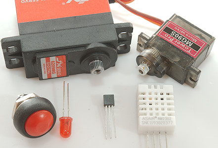
This is the second article about using Arduino with TestController, this article will contain some practical examples on devices. The examples are usable, but very simple. I have included some ideas for improving the examples.
With TestController it is possible to mix standard lab equipment (DMM, Power supplies, Loads, etc.) with the Arduino based devices and make one common logfile with all the results.
Contents
Requirements
Digital input and output module
Arduino program
Commands
TestController definition
How do it look in TestContoller
Ideas for improvement
Servo control
Arduino program
Commands
TestController definition
How do it look in TestContoller
Ideas for improvement
DS1820 temperature device
Arduino program
Commands
TestController definition
How do it look in TestContoller
Ideas for improvement
DHT22/AM2302 temperature and humidity device
Arduino program
Commands
TestController definition
How do it look in TestContoller
Ideas for improvement
Scripting
Conclusion
Notes & links
Using a Arduino with Test Controller
TestController main page
Requirements
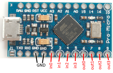
The basic requirement is a Arduino with a (virtual) serial port, nearly all Arduinos and clones qualifies for that. I often uses a Nano or ProMicro (This is not a real Arduino), they are both fairly small and can easily do simple data acquisition and control.
The inputs and outputs are not isolated from the controlling PC, in some cases this may be an issue.
Digital input and output module
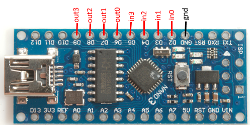
This Arduino module will provide four digital inputs and four digital outputs on Arduino voltage levels. It is possible to add external signal condition and/or change the number of IO's.
Arduino program
Code:
#define BRAND "HKJ"
#define PRODUCT "TestDigital"
#define SW_VERSION 1
#define SERIAL_NUMBER 1

// Maximum command length and buffer
const int BUF_SIZE = 50;
char cmdBuf[BUF_SIZE];

// Pin assignment
const byte in0_pin=2;
const byte in1_pin=3;
const byte in2_pin=4;
const byte in3_pin=5;
const byte out0_pin=6;
const byte out1_pin=7;
const byte out2_pin=8;
const byte out3_pin=9;

// Pullup status is read only, this means I need a place to store the current values.
byte inputPullup=0x0f;


// Accessing the different IO pins can be done with a switch or a array,
// with low number of IO pins switch can be used, with high number of IO pins array and loops is preferred.

byte readIO() {
  byte v=0;
  v|=digitalRead(in0_pin)?0x01:0;
  v|=digitalRead(in1_pin)?0x02:0;
  v|=digitalRead(in2_pin)?0x04:0;
  v|=digitalRead(in3_pin)?0x08:0;
  v|=digitalRead(out0_pin)?0x10:0;
  v|=digitalRead(out1_pin)?0x20:0;
  v|=digitalRead(out2_pin)?0x40:0;
  v|=digitalRead(out3_pin)?0x80:0;
  return v;
}

byte readOutputs() {
  byte v=0;
  v|=digitalRead(out0_pin)?0x01:0;
  v|=digitalRead(out1_pin)?0x02:0;
  v|=digitalRead(out2_pin)?0x04:0;
  v|=digitalRead(out3_pin)?0x08:0;
  return v;
}

void writeOutputs(byte v) {
  digitalWrite(out0_pin,v&0x01?HIGH:LOW);
  digitalWrite(out1_pin,v&0x02?HIGH:LOW);
  digitalWrite(out2_pin,v&0x03?HIGH:LOW);
  digitalWrite(out3_pin,v&0x04?HIGH:LOW);
}

void setInputPullup(int n,boolean on) {
  if (on) inputPullup|=1<<n;
  else inputPullup&=~(1<<n);
  pinMode(in0_pin,inputPullup&0x01?INPUT_PULLUP:INPUT);
  pinMode(in1_pin,inputPullup&0x02?INPUT_PULLUP:INPUT);
  pinMode(in2_pin,inputPullup&0x04?INPUT_PULLUP:INPUT);
  pinMode(in3_pin,inputPullup&0x08?INPUT_PULLUP:INPUT);
}


boolean readOutput(int n) {
  switch (n) {
    case 0: return digitalRead(out0_pin);
    case 1: return digitalRead(out1_pin);
    case 2: return digitalRead(out2_pin);
    case 3: return digitalRead(out3_pin);
  }
  return false;
}

void writeOutput(int n,byte v) {
  switch (n) {
    case 0: digitalWrite(out0_pin,v?HIGH:LOW);break;
    case 1: digitalWrite(out1_pin,v?HIGH:LOW);break;
    case 2: digitalWrite(out2_pin,v?HIGH:LOW);break;
    case 3: digitalWrite(out3_pin,v?HIGH:LOW);break;
  }
}

void setup() {
  Serial.begin(9600);
  // The next two lines are only needed on processors with build in USB
  unsigned long t = millis();
  while (!Serial && millis() - t < 3000); // Wait for USB connection to get ready, but do not hang when running without USB
  pinMode(in0_pin,INPUT_PULLUP);
  pinMode(in1_pin,INPUT_PULLUP);
  pinMode(in2_pin,INPUT_PULLUP);
  pinMode(in3_pin,INPUT_PULLUP);
  inputPullup=0x0f;
  pinMode(out0_pin,OUTPUT);
  pinMode(out1_pin,OUTPUT);
  pinMode(out2_pin,OUTPUT);
  pinMode(out3_pin,OUTPUT);
}

// The loop must not use delay() or delay in any other way, it has to run through in a small fraction of a second for best performance
void loop() {
  if (Serial.available() > 0) {
    int n = Serial.readBytesUntil('\n', cmdBuf, BUF_SIZE - 1);
    if (n > 0) {
      *(cmdBuf + n) = 0;
      strlwr(cmdBuf);
      char* cmd = strtok(cmdBuf, " ");
      if (strcmp(cmd, "*idn?") == 0) {
        Serial.print(BRAND);
        Serial.print(',');
        Serial.print(PRODUCT);
        Serial.print(',');
        Serial.print(SERIAL_NUMBER);
        Serial.print(',');
        Serial.print(SW_VERSION);
        Serial.print('\n');
      } else if (strcmp(cmd, "values?") == 0) {
        // This command returns all values that has to be saved in the table and used to draw curves from
        Serial.print(readIO());
        Serial.print('\n');
      } else if (strcmp(cmd, "outputs?") == 0) {
        Serial.print(readOutputs());
        Serial.print('\n');
      } else if (strcmp(cmd, "output?") == 0) {
        char *p = strtok(NULL, " ");
        if (p != NULL) {
          Serial.print(readOutput(atoi(p)));
        }
        Serial.print('\n');
      } else if (strcmp(cmd, "pullup?") == 0) {
        char *p = strtok(NULL, " ");
        if (p != NULL) {
          Serial.print(inputPullup&1<<atoi(p)?1:0);
        }
        Serial.print('\n');
      } else if (strcmp(cmd, "outputs") == 0) {
        char *p = strtok(NULL, " ");
        if (p != NULL) {
          writeOutputs(atoi(p));
        }
      } else if (strcmp(cmd, "output") == 0) {
        char *p = strtok(NULL, " ");
        if (p != NULL) {
          byte n=atoi(p);
          p = strtok(NULL, " ");
          if (p!=NULL) {
            writeOutput(n,atoi(p));
          }
        }
      } else if (strcmp(cmd, "pullup") == 0) {
        char *p = strtok(NULL, " ");
        if (p != NULL) {
          byte n=atoi(p);
          p = strtok(NULL, " ");
          if (p!=NULL) {
            setInputPullup(n,atoi(p));
          }
        }
      }
    }
  }
}
There are defined commands for handle both a single output bit or all bits at once.
Commands
- values?
Returns a single values where each input and output is a bit.
bit 0: in0, bit 3: in3, bit 4: out0, bit 7: out3
- outputs?
Get all outputs from a bitmask. bit 0=out0, bit 3=out3
- output? bitno
Returns state of a single output, the bitno is from 0 to 3
- pullup? bitno
Returns a bitmask of pins with pullup enabled.
bitno: bit 0: in0, bit 3: in3
- outputs bitmask
Sets all outputs at once
In bitmask: bit 0=out0, bit 3=out3
- output bitno state
Sets a single output
bitno: bit 0: out0, bit 3: out3
state: off: 0, on: 1
- pullup bitno state
Sets pullup on a single input
bitno: bit 0: in0, bit 3: in3
state: no-pullup: 0, pullup: 1
TestController definition
The definition must be placed in "...\doc\TestController\Devices" (On a Windows PC) in a file that has a .txt extension. It is recommended to use the BRAND and NAME for the file name.
Manual for definitions is here
Code:
; TestController must be restarted before any changes in this file will be used.

; Manual is here: https://lygte-info.dk/project/TestControllerConfigDevice%20UK.html

#idString HKJ,TestDigital,
#name HKJ Test digital IO
#handle DIO
#port comfixedbaud
; Devices with 9600 baud will be automatic found if "Scan serial ports" are checked
#baudrate 9600

; A list of possible column name with unit and formatter (SI, Time, Int, D0..D9, X1..X9)
; See here for all formatter types: https://lygte-info.dk/project/TestControllerConfigDevice%20UK.html#Data_type_definitions
#value IO _ Digital(i0,i1,i2,i3,o0,o1,o2,o3)

; All outputs must turn on when the output off button is pressed.
#outputOff outputs 0

; How to poll for data, this is used for table and #values?
; a #askMode, #cmdMode and #prepareSample is used before this is string is used.
; Number of returned values must match number of columns defined with #value
; This is a single line command
#askValues values?

; See here for all control types: https://lygte-info.dk/project/TestControllerConfigDevice%20UK.html#Configuration_menu
#cmdSetup checkbox Output
:read: output? 0
:write: output 0
o0 0 1

#cmdSetup checkbox Output
:read: output? 1
:write: output 1
o1 0 1

#cmdSetup checkbox Output
:read: output? 2
:write: output 2
o2 0 1

#cmdSetup checkbox Output
:read: output? 3
:write: output 3
o3 0 1


#cmdSetup checkbox Pullup
:read: pullup? 0
:write: pullup 0
i0 0 1

#cmdSetup checkbox Pullup
:read: pullup? 1
:write: pullup 1
i1 0 1

#cmdSetup checkbox Pullup
:read: pullup? 2
:write: pullup 2
i2 0 1

#cmdSetup checkbox Pullup
:read: pullup? 3
:write: pullup 3
i3 0 1
The datatype is defined as digital, this way it is possible to name each IO bit.
Because this module contains outputs the #outputOff tag is defined to turn all outputs off.
The settings of output state is done with checkboxes.
How do it look in TestContoller
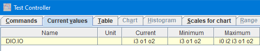
The IO bits are shown by name.
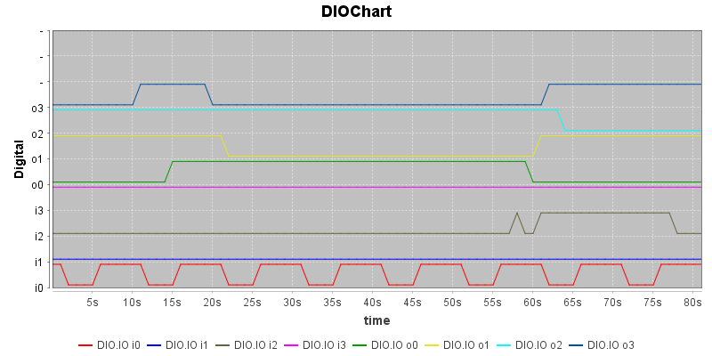
On the chart all IO bits uses the same scale, i.e. it is possible to have more curves visible at the same time.
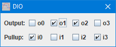
The settings are done with checkboxes
There are many other ways to see and control the Arduino device in TestController.
Ideas for improvement
The hardware could be improved with opto isolated inputs and signal condition and the output could be connected to relays or mosfet maybe with isolation.
The software could and more input measurement like frequency, puls width, pulse counter, etc. For the output it could be support for timed outputs or PWM.
Number of inputs/outputs could be adjusted.
Error checking on input values.
Add interface to support generic scripting to use the module.
Servo control
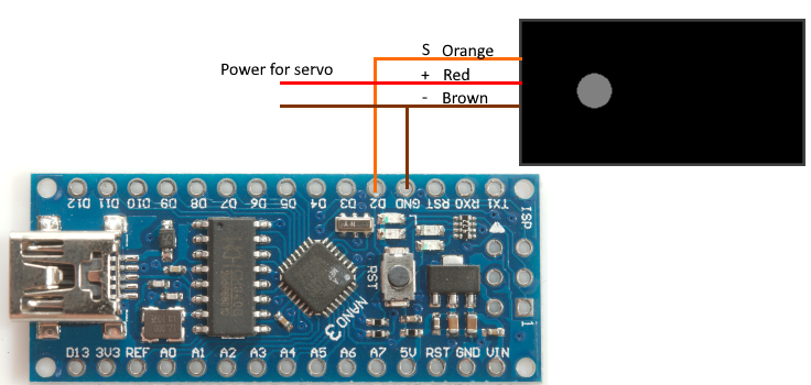
This Arduino module will control one standard servo, it can move the servo either at full speed or slowly. The slow movement can be used to log data from some item that is moved by the servo. The servo could also be used to active buttons during a automated test.
Arduino program
This code uses the standard servo library.
Code:
#include <Servo.h>
#define BRAND "HKJ"
#define PRODUCT "TestServo"
#define SW_VERSION 1
#define SERIAL_NUMBER 1

// Commands:
// pos position
// move time position
// off
// on?
// pos?
// move?

// Maximum command length and buffer
const int BUF_SIZE = 50;
char cmdBuf[BUF_SIZE];

// Pin assignment
const byte servo_pin = 2;

// Make a servo class
Servo servo;
boolean moveOn = false; // A move command is active, the off or pos command will cancel it
double pos; // Current position with decimals
double delta; // How much to change pos for each step
int steps;    // Number of steps
double targetPos = 90; // Final position when moving
double moveTime = 30; // Time to read final position when moving
long timer;     // Timer to handle 100ms background update interval

void setup() {
  Serial.begin(9600);
  // The next two lines are only needed on processors with build in USB
  unsigned long t = millis();
  while (!Serial && millis() - t < 3000); // Wait for USB connection to get ready, but do not hang when running without USB

  timer = millis();
}

// Background function to handle active move command
void move() {
  if ((millis() - timer) < 100) return; // Step 10 times each second
  timer += 100;
  if (!moveOn) return;
  if (!servo.attached()) return;
  if (steps > 1) {  // Step slowly
    pos += delta;
    servo.write(pos);
    steps--;
  } else {  // Last step is always to specified target
    pos = targetPos;
    servo.write(pos);
    moveOn = false;
  }
}

// The loop must not use delay() or delay in any other way, it has to run through in a small fraction of a second for best performance
void loop() {
  move();
  if (Serial.available() > 0) {
    int n = Serial.readBytesUntil('\n', cmdBuf, BUF_SIZE - 1);
    if (n > 0) {
      *(cmdBuf + n) = 0;
      strlwr(cmdBuf);
      char* cmd = strtok(cmdBuf, " ");
      if (strcmp(cmd, "*idn?") == 0) {
        Serial.print(BRAND);
        Serial.print(',');
        Serial.print(PRODUCT);
        Serial.print(',');
        Serial.print(SERIAL_NUMBER);
        Serial.print(',');
        Serial.print(SW_VERSION);
        Serial.print('\n');
      } else if (strcmp(cmd, "pos?") == 0) {
        Serial.print(servo.read());
        Serial.print('\n');
      } else if (strcmp(cmd, "on?") == 0) {
        Serial.print(servo.attached() ? 1 : 0);
        Serial.print('\n');
      } else if (strcmp(cmd, "move?") == 0) {
        Serial.print(moveTime);
        Serial.print(' ');
        Serial.print(targetPos);
        Serial.print('\n');
      } else if (strcmp(cmd, "off") == 0) {
        servo.detach();
        moveOn = false;
      } else if (strcmp(cmd, "pos") == 0) {
        char *p = strtok(NULL, " ");
        if (p != NULL) {
          if (!servo.attached()) {
            servo.attach(servo_pin);
          }
          moveOn = false;
          pos = atoi(p);
          servo.write(pos);
        }
      } else if (strcmp(cmd, "move") == 0) {
        char *p = strtok(NULL, " ");
        if (p != NULL) {
          double time = atof(p);
          p = strtok(NULL, " ");
          if (p != NULL) {
            moveTime = time;
            targetPos = atof(p);
            if (!servo.attached()) {
              servo.attach(servo_pin);
            }
            delta = (targetPos - pos) / moveTime * 0.1; // Calculate step size based on time
            steps = (int) abs((targetPos - pos) / delta); // Calculate steps based in step size and how much to move
            moveOn = true;
          }
        }
      }
    }
  }
}
The code do not support the "values?" command, instead a "pos?" command is used to read the servo position, both in the setup and when showing values.
Commands
- pos?
Returns current position of servo. This is the position defined by the control puls to the servo and will not reflect the correct position if the servo is blocked.
- on?
Return status of servo control
0: Off, Servo pulse is disabled, servo will not move.
1: On, Servo pulse is active, servo will move to specified location.
- move?
Last move command, it will return time and position.
- off
Turn off the servo pulse, this will stop the servo from moving from the current position.
- pos degree
Move servo to specified position, this will also turn the servo on if it is off.
degree: Position in degree. This uses the standard Arduino servo calibration and will not match all servo types.
- move time degree
Move slowly to specified degree, it will do that by giving the servo a new position 10 times each second. This will also turn the servo on if it is off.
time: Time for the move.
degree: Position in degree. This uses the standard Arduino servo calibration and will not match all servo types.
TestController definition
The definition must be placed in "...\doc\TestController\Devices" (On a Windows PC) in a file that has a .txt extension. It is recommended to use the BRAND and NAME for the file name.
Manual for definitions is here
Code:
; TestController must be restarted before any changes in this file will be used.

; Manual is here: https://lygte-info.dk/project/TestControllerConfigDevice%20UK.html

#idString HKJ,TestServo,
#name HKJ Test Servo
#handle Servo
#port comfixedbaud
; Devices with 9600 baud will be automatic found if "Scan serial ports" are checked
#baudrate 9600

; A list of possible column name with unit and formatter (SI, Time, Int, D0..D9, X1..X9)
; See here for all formatter types: https://lygte-info.dk/project/TestControllerConfigDevice%20UK.html#Data_type_definitions
#value Pos Deg x1

; All outputs must turn on when the output off button is pressed.
#outputOff off

; How to poll for data, this is used for table and #values?
; a #askMode, #cmdMode and #prepareSample is used before this is string is used.
; Number of returned values must match number of columns defined with #value
; This is a single line command
#askValues pos?

#cmdSetup indicatornum Status
:read: on?
:updatealloff:
Off 99 red
On 1 red

; See here for all control types: https://lygte-info.dk/project/TestControllerConfigDevice%20UK.html#Configuration_menu
#cmdSetup number Position
:read: pos?
:write: pos
:tip: Position will not be updated after a slow move.
:update: Status
Deg 0 180

#cmdSetup Multi Slow_move
:read: move?
:write: move
:update: Status
:buttontext: Start
number Time s 0.5 600
number Pos Deg 0 180

#cmdSetup button Off
:write: off
:update: Status
The only information to show is the servo position.
How do it look in TestContoller
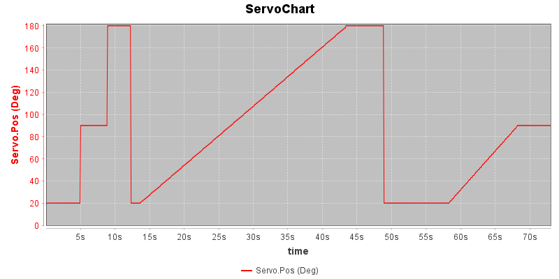
The servo, if some parameter depend on the angle, the angle can be moved to the x-axis.
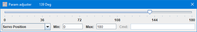
The adjuster makes it easy to slide the servo position around.
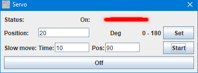
For more precise control or slow movement the setup menu can be used.
There are many other ways to see and control the Arduino device in TestController.
Ideas for improvement
More servos could be added.
The software could add calibration and range check for each servo.
Adding a poke command, i.e. pulse the servo to a position and back again, could be useful for activating a button during tests.
Add interface to support generic scripting to use the module.
Error checking on input values.
DS1820 temperature device
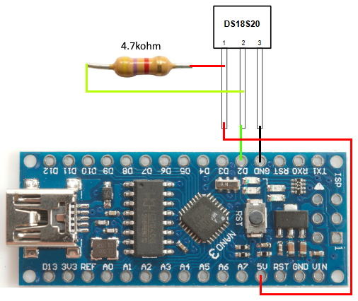
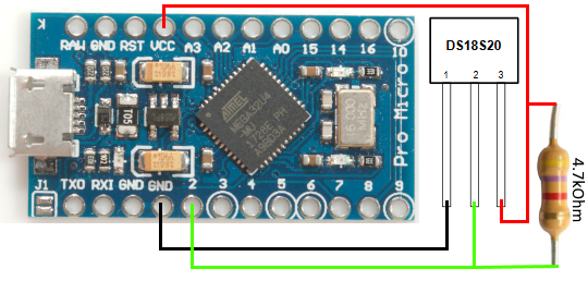
This Arduino module will read one DS1820 temperature sensor. This is a digital sensor, i.e. no ADC is required, it is included in the sensor.
Arduino program
This code uses the onewire and DallasTemperature libraries.
Code:
#include <OneWire.h>
#include <DallasTemperature.h>

#define BRAND "HKJ"
#define PRODUCT "TestDS1820"
#define SW_VERSION 1
#define SERIAL_NUMBER 1

// Maximum command length and buffer
const int BUF_SIZE = 50;
char cmdBuf[BUF_SIZE];

const byte Temperature_pin = 2;

OneWire oneWire(Temperature_pin);
DallasTemperature dsSensor(&oneWire);
DeviceAddress dsAddress;
boolean isDsSensor = false;
double temp = 0;
long timer = 0;

void setup() {
  Serial.begin(9600);
  // The next two lines are only needed on processors with build in USB
  unsigned long t = millis();
  while (!Serial && millis() - t < 3000); // Wait for USB connection to get ready, but do not hang when running without USB
  dsSensor.begin();
  findSensor();
  timer = millis();
}

void findSensor() {
  temp = 0;
  if (dsSensor.getDS18Count() == 1 && dsSensor.getAddress(dsAddress, 0)) {
    isDsSensor = true;
    dsSensor.setResolution(dsAddress, 12);
    dsSensor.setWaitForConversion(false);
    dsSensor.requestTemperatures();
  } else {
    isDsSensor = false;
  }

}

void updateTemp() {
  if (!isDsSensor) return;
  if ((millis() - timer) < 900) return; //Update slower than conversion, sensor uses up to 0.75 second for a conversion
  temp = dsSensor.getTempC(dsAddress);
  if (temp == DEVICE_DISCONNECTED_C ) {
    isDsSensor = false;
    return;
  }
  dsSensor.requestTemperatures();
  timer = millis();
}

void loop() {
  updateTemp();
  if (Serial.available() > 0) {
    int n = Serial.readBytesUntil('\n', cmdBuf, BUF_SIZE - 1);
    if (n > 0) {
      *(cmdBuf + n) = 0;
      strlwr(cmdBuf);
      char* cmd = strtok(cmdBuf, " ");
      if (strcmp(cmd, "*idn?") == 0) {
        Serial.print(BRAND);
        Serial.print(',');
        Serial.print(PRODUCT);
        Serial.print(',');
        Serial.print(SERIAL_NUMBER);
        Serial.print(',');
        Serial.print(SW_VERSION);
        Serial.print('\n');
      } else if (strcmp(cmd, "find") == 0) {
        findSensor();
      } else if (strcmp(cmd, "sensor?") == 0) {
        Serial.print(isDsSensor ? 1 : 0);
        Serial.print('\n');
      } else if (strcmp(cmd, "value?") == 0) {
        Serial.print(temp);
        Serial.print('\n');
      }
    }
  }
}
I use a "value?" command to get the sensor value, the actual sensor reading is performed in the background.
Commands
- value?
Report the current temperature
- sensor?
Returns 1 if a single DS1820 is connected and working, else 0
- find
Start a search for a DS1820 sensor, use the "sensor?" command to check if a DS1820 is found.
This search will automatically be done when power is applied, the only time the "find" command is needed is if the sensor is changed without cycling power.
TestController definition
The definition must be placed in "...\doc\TestController\Devices" (On a Windows PC) in a file that has a .txt extension. It is recommended to use the BRAND and NAME for the file name.
Manual for definitions is here
Code:
; TestController must be restarted before any changes in this file will be used.

; Manual is here: https://lygte-info.dk/project/TestControllerConfigDevice%20UK.html

#idString HKJ,TestDS1820,
#name HKJ Test DS1820
#handle DS1820
#port comfixedbaud
; Devices with 9600 baud will be automatic found if "Scan serial ports" are checked
#baudrate 9600


; A list of possible column name with unit and formatter (SI, Time, Int, D0..D9, X1..X9)
; See here for all formatter types: https://lygte-info.dk/project/TestControllerConfigDevice%20UK.html#Data_type_definitions
#value Temperature °C D2
; Due to the ° (grad) symbol this file must be saved in unicode with a BOM marker to be reliable on all OS's

; How to poll for data, this is used for table and #values?
; a #askMode, #cmdMode and #prepareSample is used before this is string is used.
; Number of returned values must match number of columns defined with #value
; This is a single line command
#askValues value?

#cmdSetup indicatorNum Sensor_valid
:read: sensor?
No 0 red
Yes 1 green

#cmdSetup button Find_sensor
:write: find
:update: Sensor_valid
:tip: Search the one wire bus for a sensor, code will only work with one sensor
How do it look in TestContoller
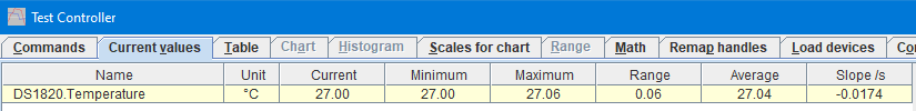
A single temperature sensor will show a single a single temperature and some statistic.
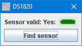
There is not really any settings on a DS1820, but it is possible replace the sensor and find it.
There are many other ways to see and control the Arduino device in TestController.
Ideas for improvement
A offset compensation that is stored in EEPROM would probably improve accuracy slightly.
Display to show temperature (Use my library for LED displays).
More than one sensor.
Add interface to support generic scripting to use the module.
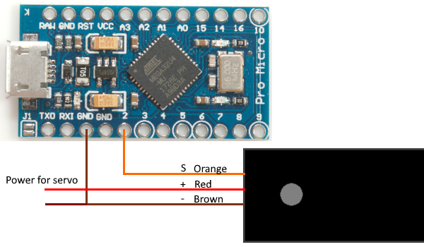
DHT22/AM2302 temperature and humidity device
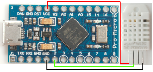
This Arduino module will read one DHT22/AM2302 temperature and humidity sensor, this can be used to log the ambient conditions during a test.
The connection above only shows the ProMicro, because I have only checked with that processor, the nano may have problems with the serial interrupt disrupting the data transfer and giving wrong values.
This project is very simple and do not really need any improvements for practical usage.
Arduino program
This code uses my DHT22 sensor library. I have included the DHT22 files in the zip file, if these files are place in the same directory as the program it will work. It is also possible to download the DHT22 library from my website and include it.
Code:
#include

#define BRAND "HKJ"
#define PRODUCT "TestDHT22"
#define SW_VERSION 1
#define SERIAL_NUMBER 1

// Maximum command length and buffer
const int BUF_SIZE = 50;
char cmdBuf[BUF_SIZE];

const byte Sensor_pin = 2;

DHT22 dht(Sensor_pin);

float temperature = 0;
float humidity = 0;

void setup() {
  Serial.begin(9600);
  // The next two lines are only needed on processors with build in USB
  unsigned long t = millis();
  while (!Serial && millis() - t < 3000); // Wait for USB connection to get ready, but do not hang when running without USB
}

void updateTemp() {
  if (!dht.ready()) return;
  dht.measure(temperature, humidity);
}

void loop() {
  updateTemp();
  if (Serial.available() > 0) {
    int n = Serial.readBytesUntil('\n', cmdBuf, BUF_SIZE - 1);
    if (n > 0) {
      *(cmdBuf + n) = 0;
      strlwr(cmdBuf);
      char* cmd = strtok(cmdBuf, " ");
      if (strcmp(cmd, "*idn?") == 0) {
        Serial.print(BRAND);
        Serial.print(',');
        Serial.print(PRODUCT);
        Serial.print(',');
        Serial.print(SERIAL_NUMBER);
        Serial.print(',');
        Serial.print(SW_VERSION);
        Serial.print('\n');
      } else if (strcmp(cmd, "values?") == 0) {
        Serial.print(temperature);
        Serial.print(' ');
        Serial.print(humidity);
        Serial.print('\n');
      } else if (strcmp(cmd, "sensor?") == 0) {
        Serial.print(dht.isError() ? 0 : 1);
        Serial.print('\n');
      }
    }
  }
Commands
- values?
Returns temperature and humidity.
- sensor?
Return 1 if a DHT22/AM2302 is connected and working else 0.
TestController definition
The definition must be placed in "...\doc\TestController\Devices" (On a Windows PC) in a file that has a .txt extension. It is recommended to use the BRAND and NAME for the file name.
Manual for definitions is here
Code:
; TestController must be restarted before any changes in this file will be used.

; Manual is here: https://lygte-info.dk/project/TestControllerConfigDevice%20UK.html

#idString HKJ,TestDHT22,
#name HKJ Test DHT22
#handle DHT22
#port comfixedbaud
; Devices with 9600 baud will be automatic found if "Scan serial ports" are checked
#baudrate 9600


; A list of possible column name with unit and formatter (SI, Time, Int, D0..D9, X1..X9)
; See here for all formatter types: https://lygte-info.dk/project/TestControllerConfigDevice%20UK.html#Data_type_definitions
#value Temperature °C D1
#value Humidity %RH D1
; Due to the ° (grad) symbol this file must be saved in unicode with a BOM marker to be reliable on all OS's

; How to poll for data, this is used for table and #values?
; a #askMode, #cmdMode and #prepareSample is used before this is string is used.
; Number of returned values must match number of columns defined with #value
; This is a single line command
#askValues values?

#cmdSetup indicatorNum Sensor_valid
:read: sensor?
No 0 red
Yes 1 green
How do it look in TestContoller
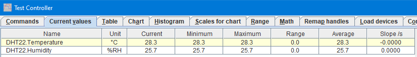
This sensor shows temperature and humidity.
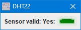
There is no settings for this example, but I shows the error flag.
There are many other ways to see and control the Arduino device in TestController.
Ideas for improvement
A offset compensation that is stored in EEPROM would probably improve accuracy slightly.
Display to show temperature (Use my library for LED displays).
Add interface to support generic scripting to use the module.
Scripting
One improvement for all the examples is to add generic scripting, this makes it possible for scripting to use any module with that functionality, usually without any changes to the script.
This is not necessary to use the module from scripting, it can always be used:
1) Right click in log window and select "Generate scripts, Mode & Setup, Clear saved commands" (If "Mode & Setup" is missing this is not necessary).
2) Use the "Setup" popup and select the commands
3) Right click in log window and select "Generate scripts, Mode & Setup, In log window" and the scripts for the setup will be put into the log window (It can also be saved as a menu entry).
Values from the devices can be found in variables while logging is active, these variables have the same name as the columns on the "Table" page or use the #values? command, it will list them all, including their current value.
But scripts generated that way may only work with that module, not with other models or brands.
Conclusion
These devices are for test and demonstration purpose, for this reason they are made fairly simple. All devices can be build and used, but as can be seen above I have a lot of ideas about how to improve them.
Checking the "Scan serial ports" on the "Load devices" page and storing the definitions in the specified directory is enough to make TestController find the devices, they do not need to be loaded.
Some Arduino devices will show up on my project page over time, they will include schematic, gerber files, Arduino program and TC definition and be considerable more complex than the examples shown here.
Notes & links
TestController main page
TestController manual for SCPI definitions
Projects, including Arduino library and devices for TestController
Temperature and humidity (DHT22/AM2302) library
Arduino code & TC definition