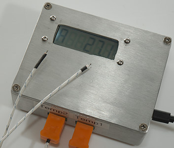
I wanted a box to handle two thermocoupler as input to my logging software. The problem with thermocouplers is that they are metal wires, this means there is electric connection from what they touch to the measurement circuit. The idea here was to add isolation from the PC and also between the two thermocouplers. I could do that with two multimeters with logging output and have used that before, but this time I decided to make a box that could do it.
MAX31855: 14 bit with 0.25°C resolution, must be bought for specific thermocoupler type, uses SPI bus.
MAX31856: 19 bit with 0.0078125°C resolution, support many thermocoupler types, uses SPI bus.
MAX31850/MAX31851: 14 bit with 0.25°C resolution, 1 wire bus.
MAX6675: 12 bit with 0.25°C resolution, uses SPI bus.
MCP9600: 16 bit with maybe 0.0625°C resolution, uses I2C bus.
Not that many different chips, the MAX31856 and MCP9600 was the most interesting types and because I wanted isolation the MAX31856 (A SPI bus is easy to isolate) looked like the best option.
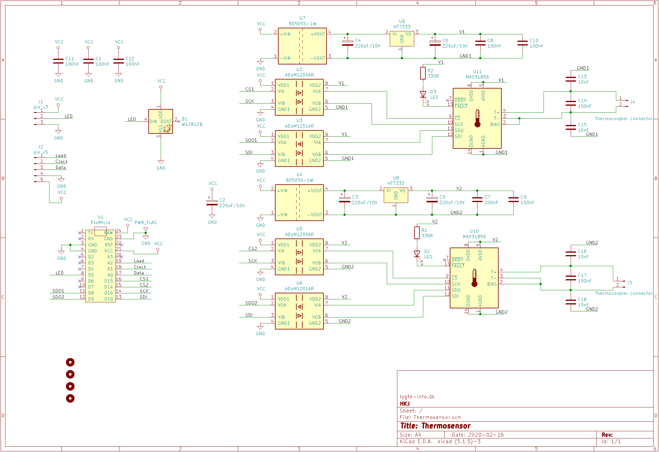
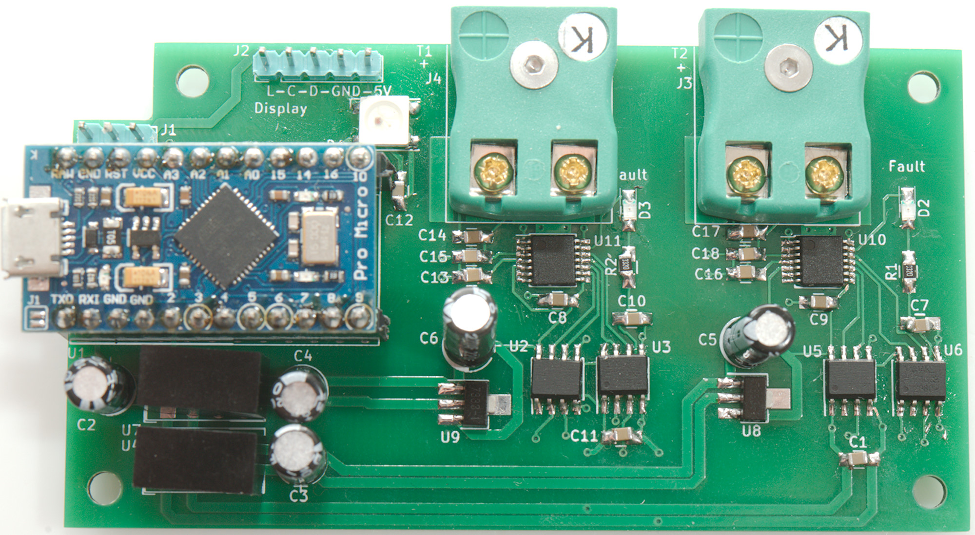
The schematic was fairly easy to do, the chips I use for the isolation (ADuM1200/ADuM1201) is some I have used in another project, they are fast and works on both 5V and 3.3V. I used 5V to 5V isolation converters with a 3.3V regulator after them. Converters are usually not stabilized on the output and the voltage will vary with input voltage. With the external regulator I get precise and stable 3.3V. I had to use separate pins on the Arduino for MAX31856 outputs (SDI pin) and CS.
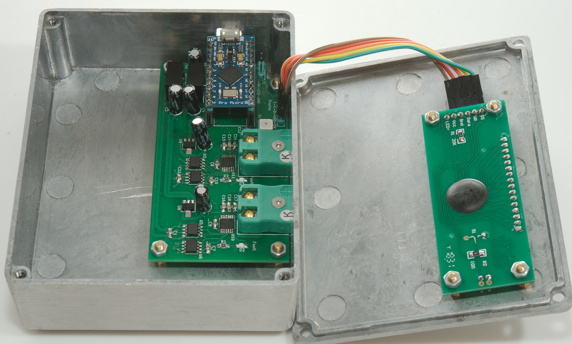
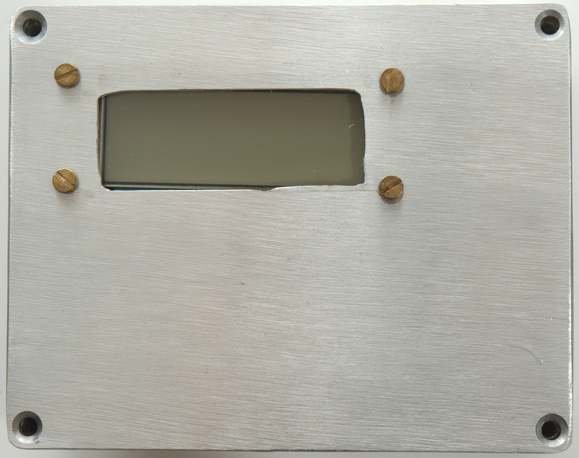
I added a status led and a connector for a display.
I added leds to the fault output on the MAX chip, they may be useful when testing.
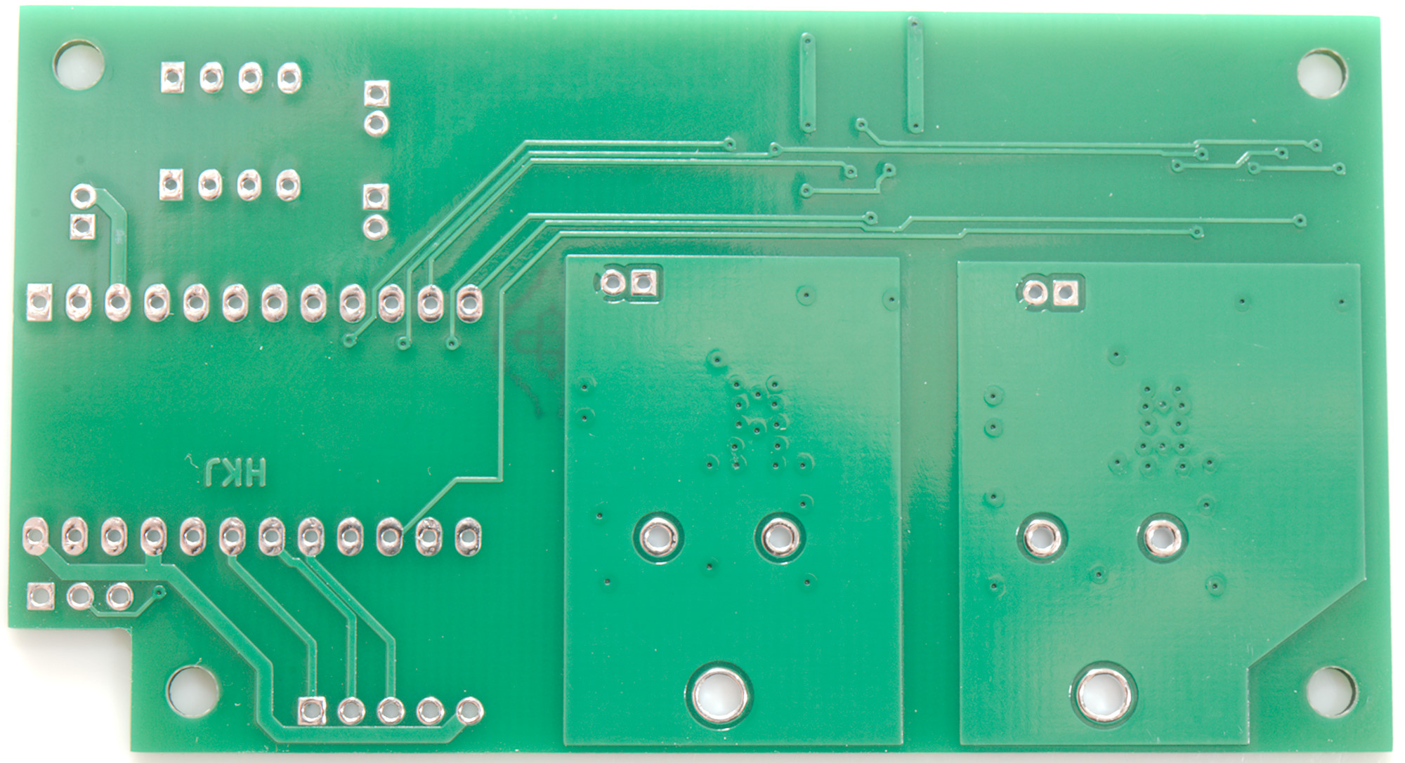
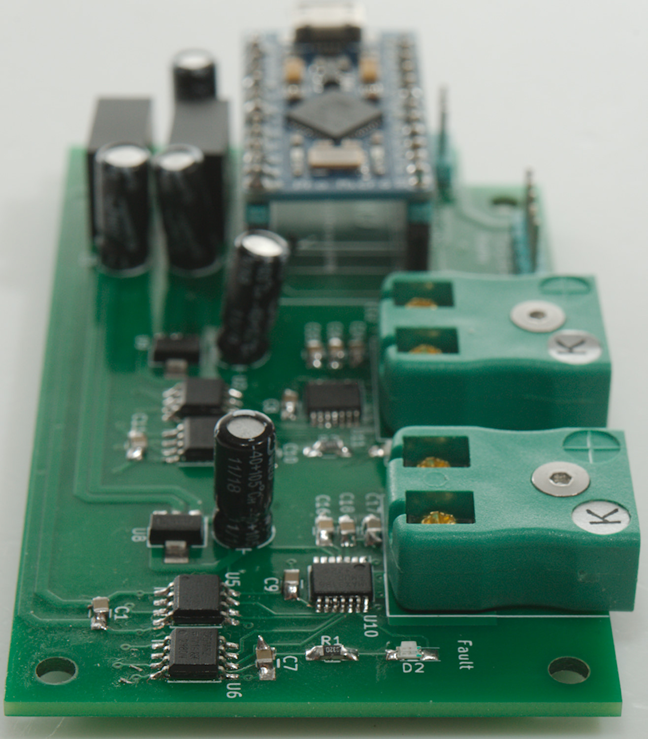
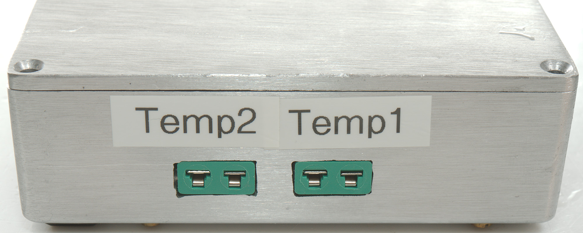
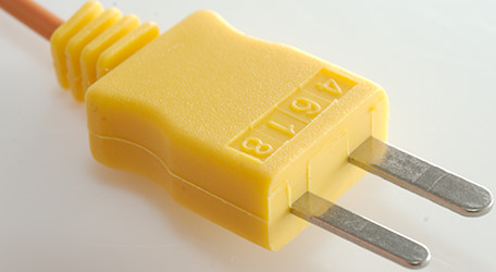
I got some real thermocoupler connectors for circuit board montage, mine are designed for K type thermocoupler, this means the temperature reference is the point where the connector is soldered to the circuit board. I could have got some in copper that would move the point to the actual connection between the plug and the socket. I have used a copper area under the connector and chip to get the best possible heat equalization.
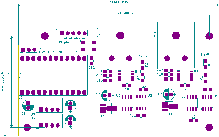
The DC-DC converters is a significant heat source and I placed them as far from the termocouplers as possible. The Arduino is also a heat source, but the socket reduces the heat transfer a bit.
For isolation the maximum distance is limited by the DC-DC converters and I made sure all other distance was larger than that.
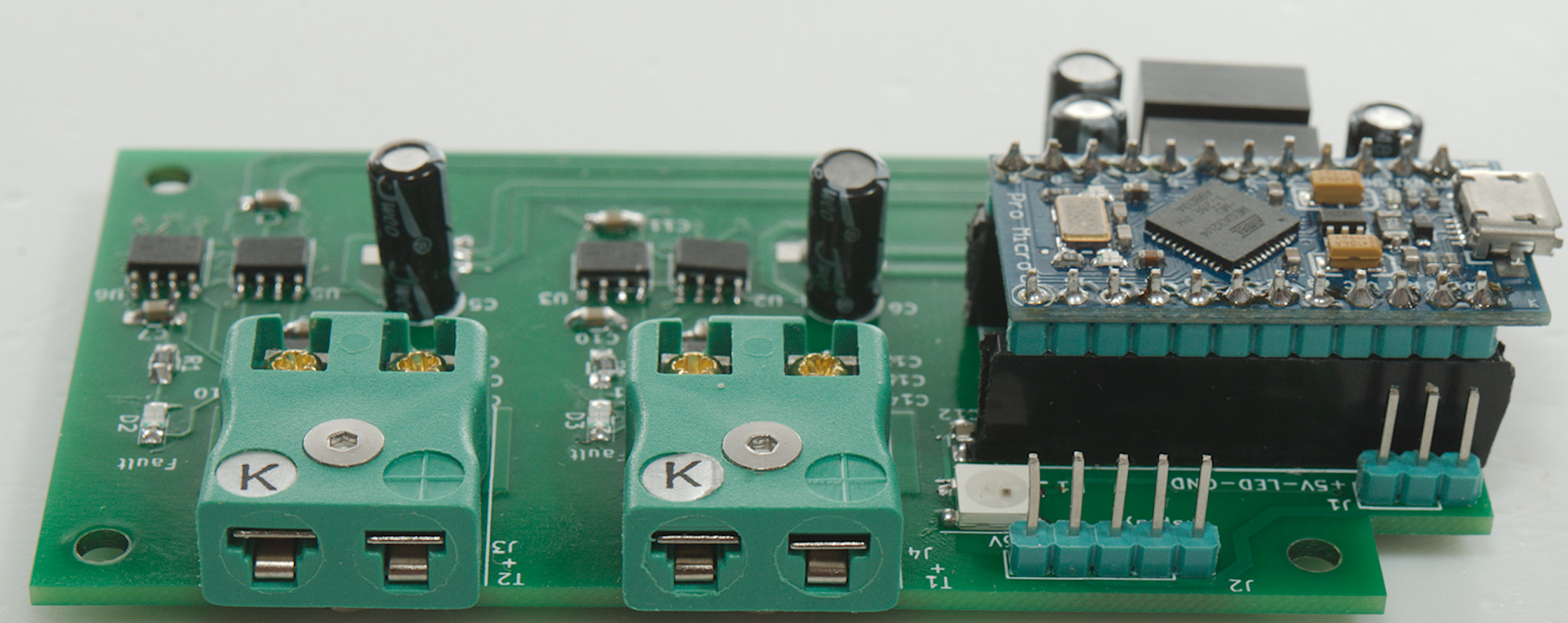
The layout with Arduino micro usb on the left and the two termocoupler connectors on the top may not be ideal for distances, but means the PCB will fit in just about any box that is large enough.
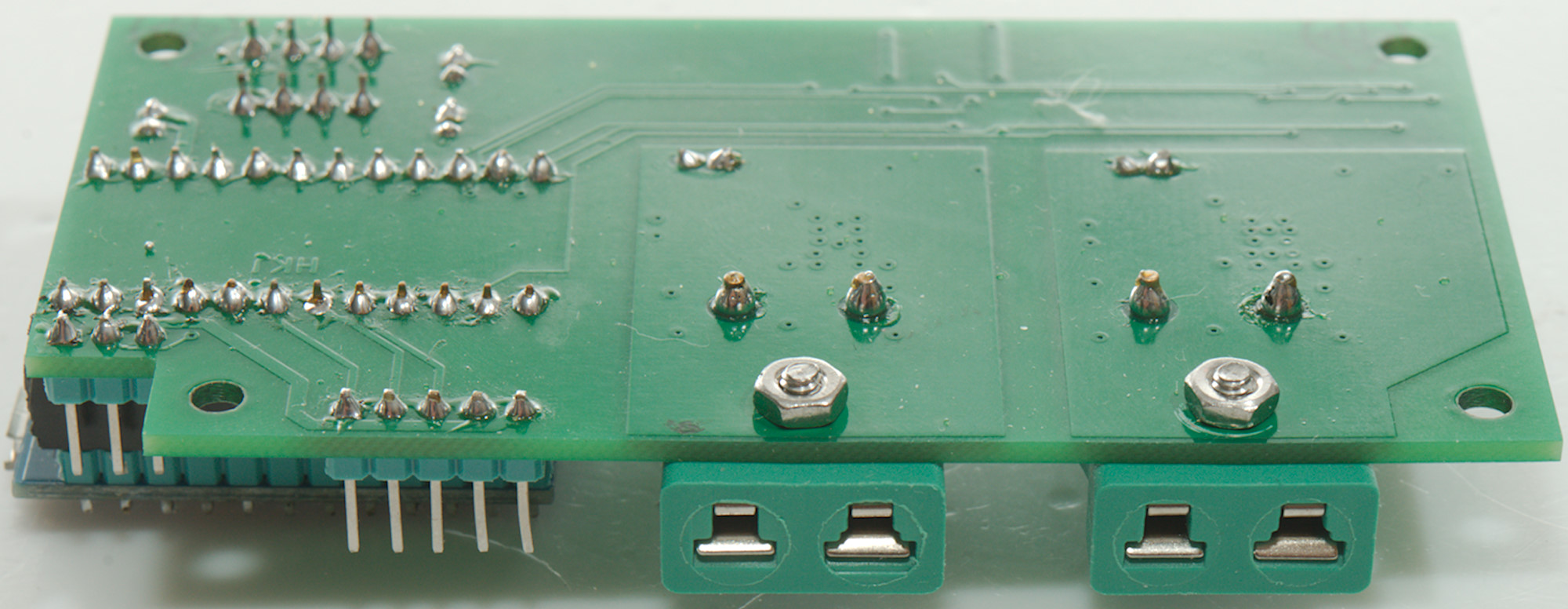
The MAX chip is rather small and it do not exist in a larger package. The two thermocoupler connectors are just enough over the edge of the PCB to go through the enclosure. They are also screwed down, making the very robust.
Define fault/alarm/warning limits, when temperature is outside these limits an alarm will be shown and the ERROR? command will report it. There is no specific way to disable these limits, just place the limits outside normal operating range. The reading command will only show values for enabled channels.
Define thermocoupler type used, default is type K and when using type K connector other types are not recommended. For voltage input specify x8 or x32 as sensor type.
Code:
SENSOR 1 K
SENSOR 2 x8
SENSOR B x32
SENSOR?
In x8 mode it is possible to measure from -35mV to 110mV
In x32 mode it is possible to measure from -8.8mV to 27mV
Supported thermocouplers are: B, E, J, K, N, R, S, T
Specify number of samples to average, the MAX31856 can do up to 16 values, after that I have added a running average of up to 64 values. The actual number of samples is specified as an index:
0: MAX31856 do not average, software do not average
1: MAX31856 averages 2 samples, software do not average
2: MAX31856 averages 4 samples, software do not average
3: MAX31856 averages 8 samples, software do not average
4: MAX31856 averages 16 samples, software do not average
5: MAX31856 averages 16 samples, software is doing a running average of 2 samples.
6: MAX31856 averages 16 samples, software is doing a running average of 4 samples.
7: MAX31856 averages 16 samples, software is doing a running average of 8 samples.
8: MAX31856 averages 16 samples, software is doing a running average of 16 samples.
9: MAX31856 averages 16 samples, software is doing a running average of 32 samples.
10: MAX31856 averages 16 samples, software is doing a running average of 64 samples.
With 16 samples there is a new value every 0.9 second, with 16+64 samples a 58 seconds averaging is added to that.
The MAX31856 can operate in two modes, either on-demand (Sample) or automatic (Run). Without a connection to the DRDY pin it is not possible to know when a sample is done in automatic mode, the software will just do 5 samples each second. In on-demand mode the software can time conversions and will know when a sample is done.
This means that on-demand (Sample) is usual the best mode.
The cold junction is usual measured inside the chip, but it is possible to store a fixed value. Use A to return to automatic, i.e. updating from internal temperature sensor.
This command will return two or four values depending on number of sensors enabled. It will be thermocoupler temperature followed by cold juntion temperature first for sensor 1 and then for sensor 2. Usually with 2 decimals, but in volt mode it is millivolt with 3 decimals.
Using this command will switch to listing mode where the output can be directly saved to a file and used as input to PC programs. It will first list a header and then stream the data with one line each second. Any command (including invalid commands) will stop this listing. The command with or without question mark is exactly the same.
The 3 formats supported are:
LIST: List without parameters will use a TAB delimited list with . as decimal comma.
LIST .: With a . it will use a CSV format with , as delimeter and . as decimal comma.
LIST ,: With a , it will use a CSV format with ; as delimeter and , as decimal comma.
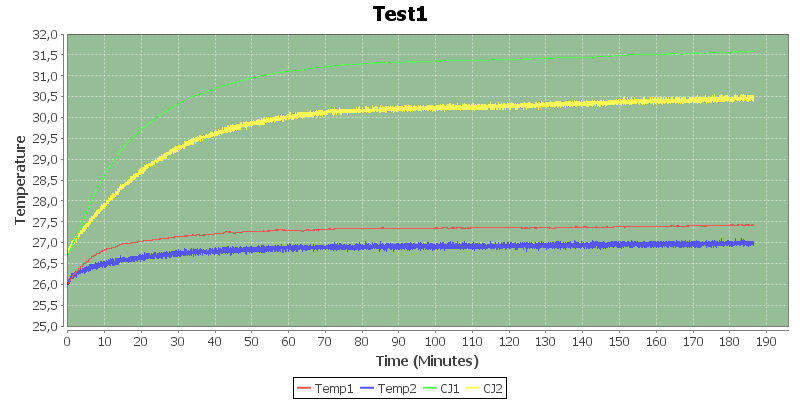
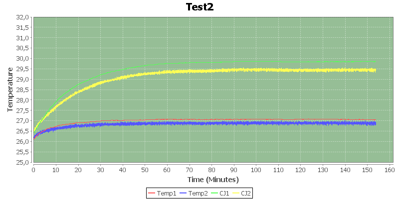
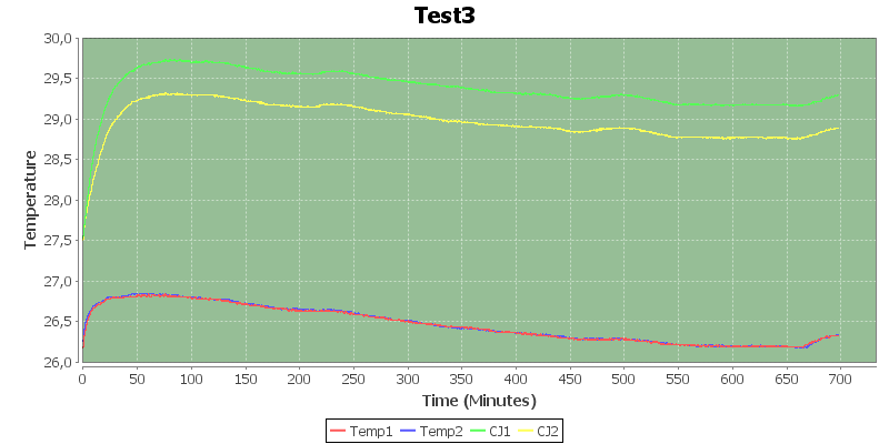
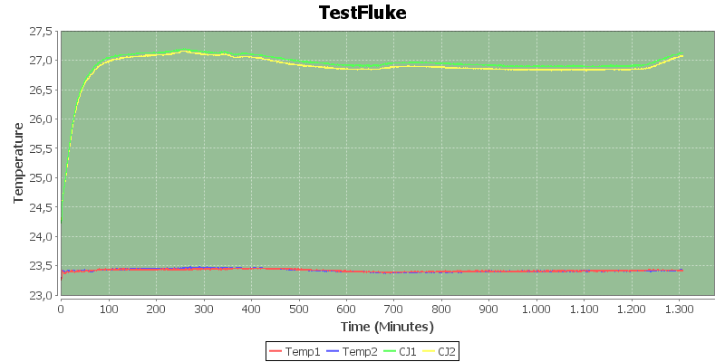
After the software and hardware is working the first test is recording a few hours of stable temperature:
Temp1 & CJ1 uses 16+64 samples, Temp2 & CJ2 uses 16 samples. The extra running average looks very good at reducing noise.
But I did say something about stable temperature and it do not look very stable, sensor 1 register a internal temperature raise 4.9°C and sensor 2 of 3.7°C. This by itself it not a huge problem as long as it is close to the connector temperature, but temp1 shows an increase of about 1.4°C and temp2 of 1.0°C, this is a bit much.
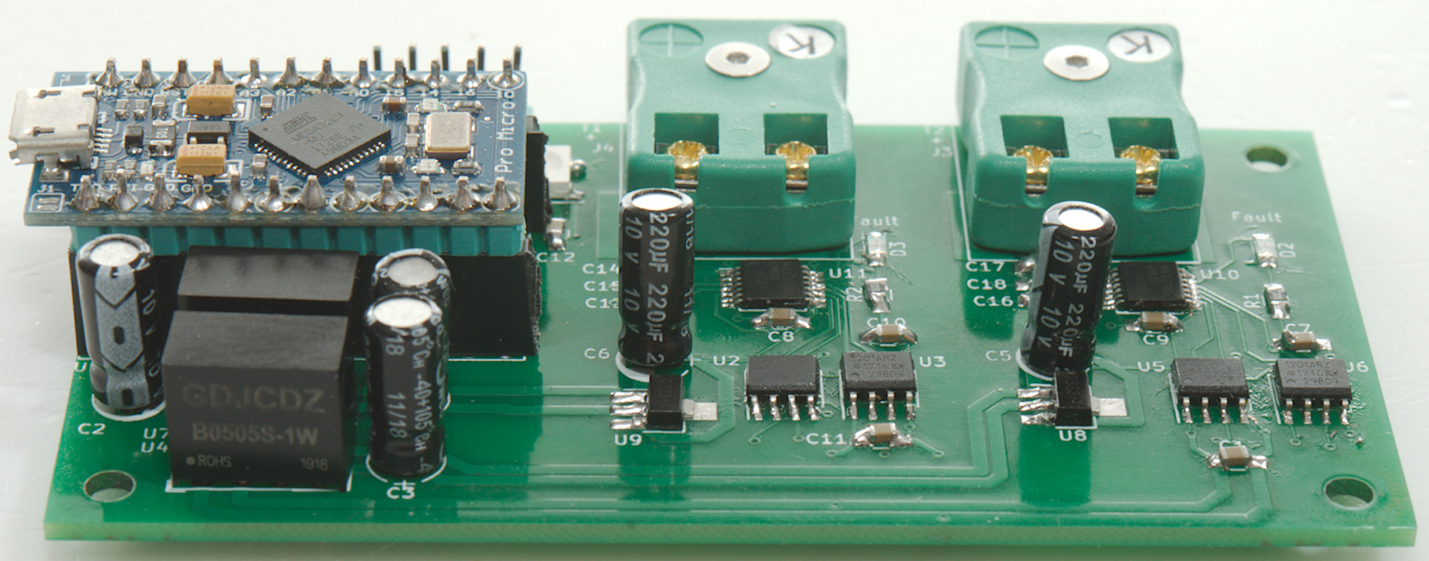
The problem is the power dissipated in the enclosure, measuring the current I get about 110mA, this means 0.55W inside the box.
This splits roughly into Arduino 30mA, display 20mA and DC-DC converters 30mA each.
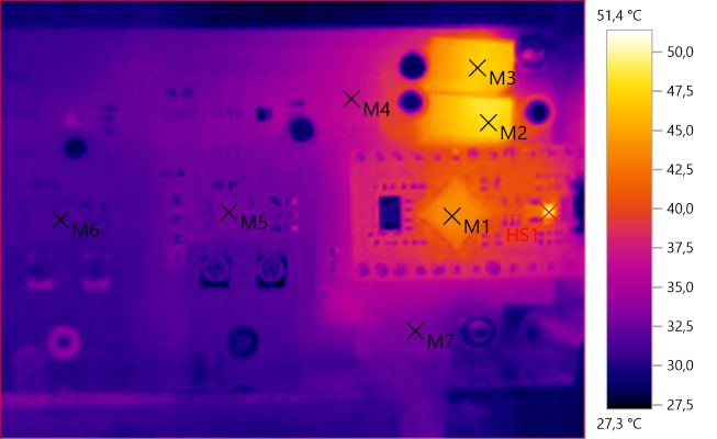
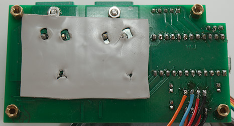
M1: 43.7°C, M2: 47.8°C, M3: 47.1°C, M4: 36.2°C, M5: 32.8°C, M6: 31.0°C, M7: 33.1°C, HS1: 51.4°C
A temperature photo of the circuit board after a couple of hours on time. As can be seen the two DC-DC converters are warm (47°C), on the Arduino the warmests part is a diode (51°C) followed by the processor (44°C). None of this would be a problem, except I need a PCB without temperature gradients.
This is very obvious when looking at the two MAX chips (31.0°C & 32.8°C), there above curve shows 1.2°C in difference.
Can I do something to improve this?
Checking my stock of DC-DC converters I found out that idle current varied between 22mA and 28mA. The two converters I used was 25mA and 28mA.
Replacing them by 22mA idle current converters and adding SLEEP mode (The sleep mode is active between millis interrupts, this means the processor spends 95% of the time in sleep) and disabling unused peripherals in the Arduino I got down to 95mA (92mA when not streaming data) current consumption.
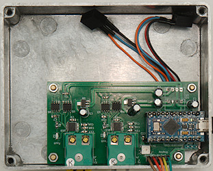
I did also move the converters away from the circuit board. This will not reduce the heat inside the box, but moves the heat away from the circuit board with the MAX chips on it.
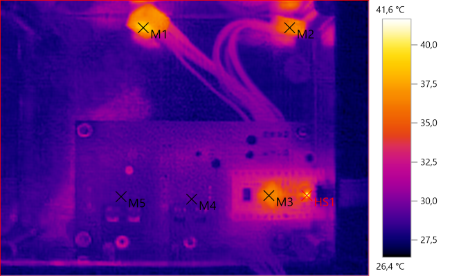
M1: 38.8°C, M2: 36.3°C, M3: 36.4°C, M4: 29.1°C, M5: 28.9°C, HS1: 41.6°C
With the two converters move away the PCB is cooler and the temperature gradient is smaller, the difference between the two MAX chips is now only 0.2°C. Did this improve the curves?
The answer must be yes, but I still have nearly 1°C temperature change on temp1 at the start, most of it can be avoided if I let the box warm up for 20 minutes before using it.
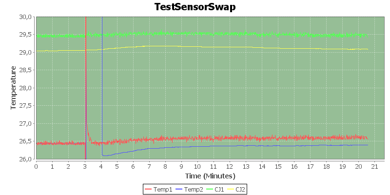
Here I did a longer run (A night) with full averaging on both channels. On strange thing is that the two sensors are exactly the same.
Swapping the sensors explains why. The reason temp2 needs a minute to recover (From 3 to 4 minute on scale) is the averaging.
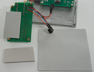
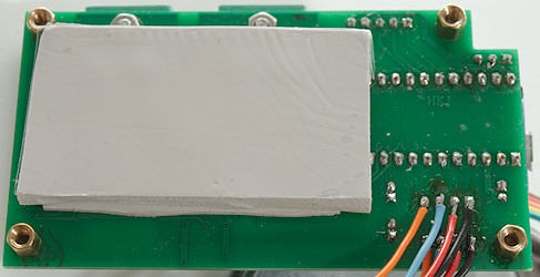
I had one more idea for improvement, add a thermo transfer pad between the PCB and the box. The stuff is easy to cut.
Due to the distance between the PCB and the box I used two layers, in the layer nearest the PCB I cut holes for the solderings on the PCB.
Both layers mounted. I did not remove the thin film on the bottom pad, this means worse heat transfer, but also that I can easily take the PCB out.
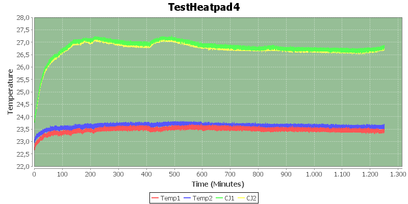
A 21 hours test, with the heat pad the two MAX chips tracks perfectly in temperature, but I still have a nearly 1°C drift on the thermocouplers.
It looks like the box get heated about 3°C with the power I use in it.
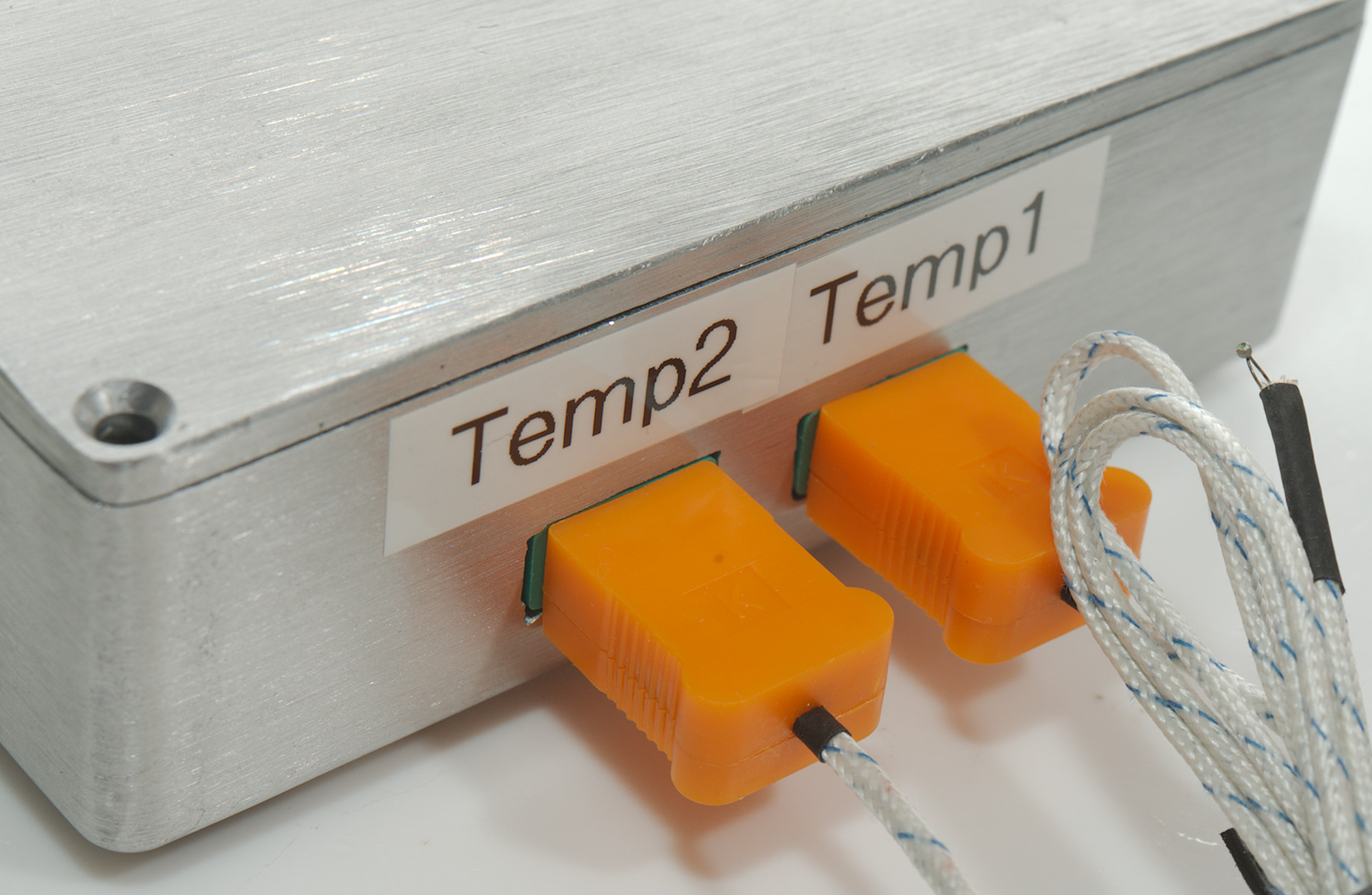
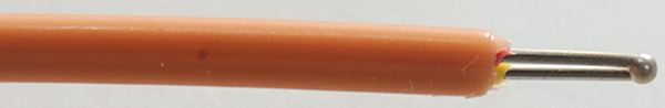
I started getting suspicious about the termocouplers, could there be something wrong with them, more specific the connector. It is supposed to be made of the same alloy as the two wires to not generate any thermoelectric voltage. Could it be the cheap termocouplers just uses some cheap metal. Thinking that basically answered the question also.
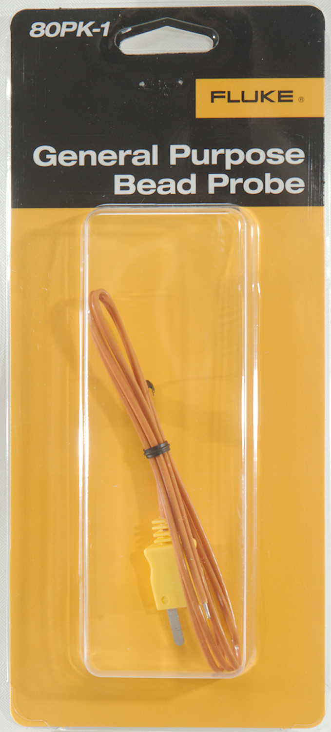
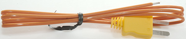
I decider to get some expensive and high quality termocouplers.
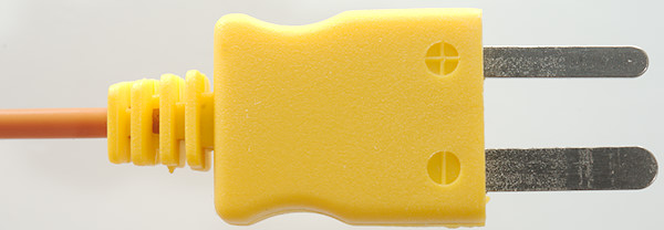
They are much better build quality with thicker wires and moulded connector with strain relief.
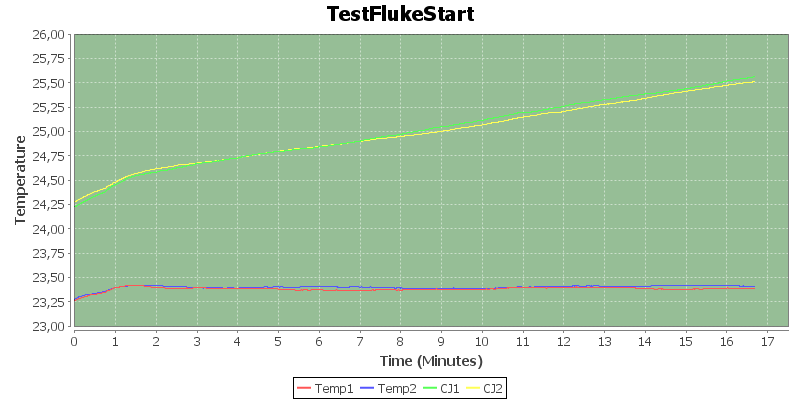
A 21 hours test and there is no temperature raise on the sensors when the box warms up, it was the faulty connectors. The MAX31856 nicely compensates for the warmer box. I did this curve with a 1 minute average to reduce the noise.
There is still a 0.2°C temperature raise the first minute, I expect that is due to initialization and warm-up, the one minute may be related to my one minuted average.
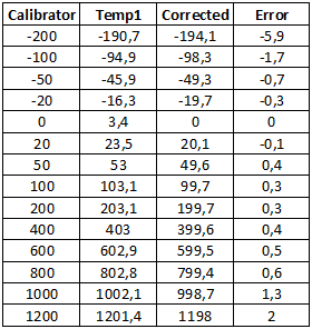
How precise is the MAX31856 chip? Here I compared it to a calibrator and it follows it nicely, except at very cold temperatures (The calibrator matches my DMM6500 within 0.3°C from -100°C to 800°C).
In the corrected column I have removed any cold junction mismatch between calibration and MAX chip. The error column is error in degrees Celsius.
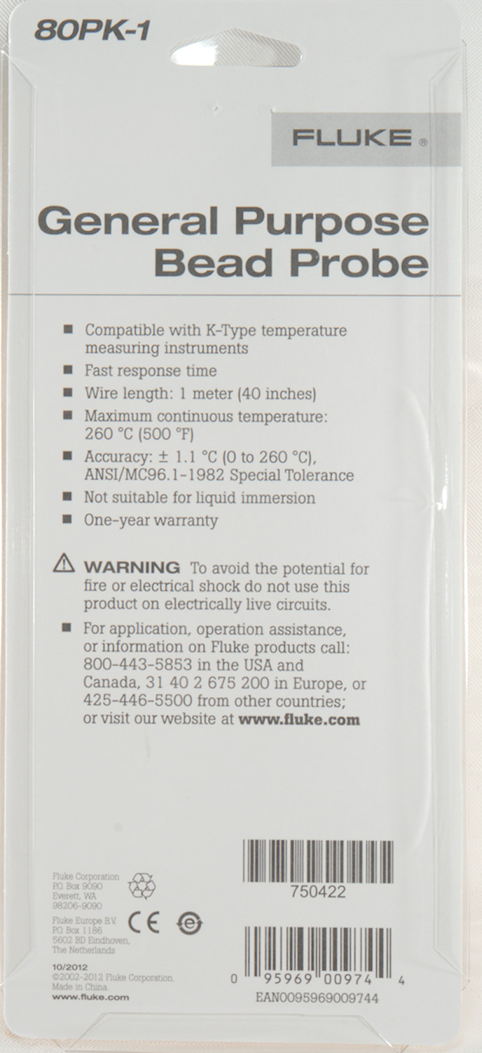
The datasheet for the MAX31856 says it is within -0.13°C +0.12°C linearity error. The cold-junction is within +/-0.7°C and the Fluke thermocoupler is within +/-1.1°C, this means the total error is around +/-2°C on absolute temperature, but I have a very good resolution on temperature changes.
This project had a couple of problems, but they where solved in the end and the final result is everything I wanted. I can easily see 0.1°C temperature changes and the absolute reading is within 2°C. The small thermocouplers can be mounted on heat sinks or larger transistors and I do not have to worry about isolation (At least when working well below mains voltage).
If I am going to make more of these I will put a slot on the circuit board between the processor+DC-DC and the MAX31856 and try again with mounting the DC-DC on the circuit board. I will also keep the heat transfer pads and the metal enclosure.
The slot would be something like this. This would require moving some parts and rerouting part of the PCB.