DMM Amprobe AM-570
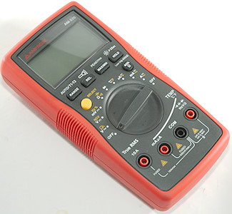
This is the top meter in the Amprobe 5xx series, it is well packed with functions and has fairly good specifications.
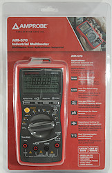


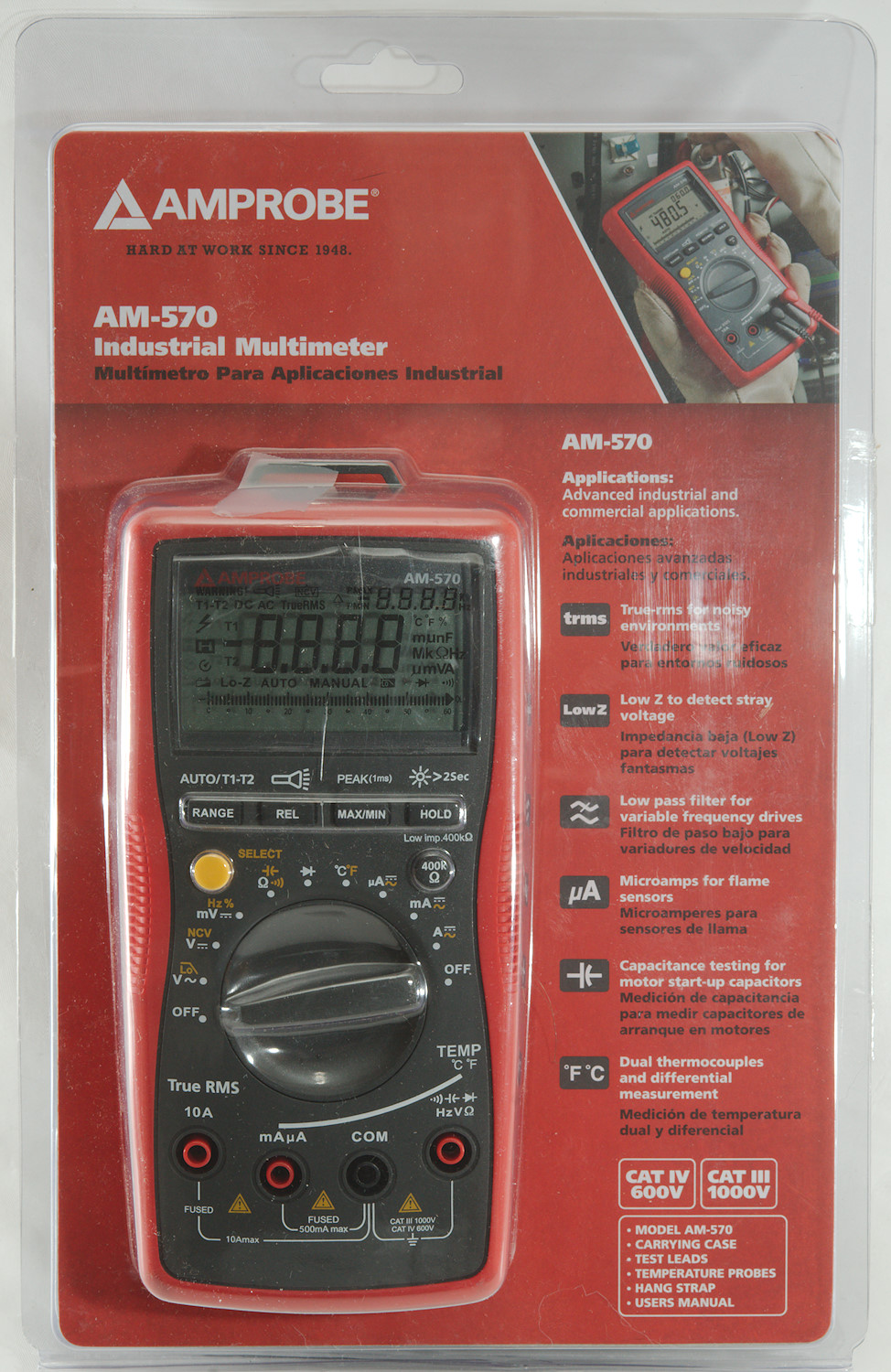
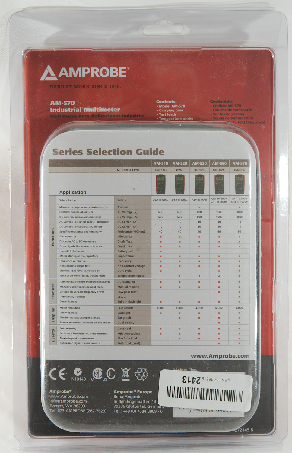
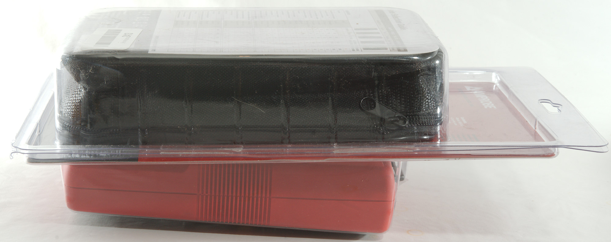
The meter is packed in a clamshell box, on the front it has some highlights for this meter and on the back it compares the different models in the 5xx series.
The 540 and 550 is missing, they are basically the same as 560 and 570, but with different safety ratings and only sold in EU.
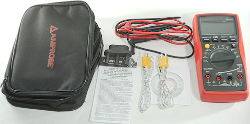
It included the DMM, a pouch, a pair of probes, two thermocouples and a dual thermocoupler adapter, a safety information sheet and a mini CD with the manual (It can also be downloaded).
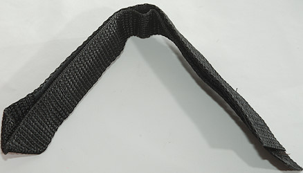
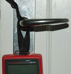
I forgot this strap in the above picture. It can be used to hang the meter from all types of hooks.
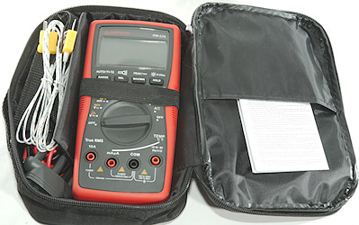
Everything could fit in the supplied pouch.
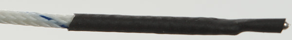
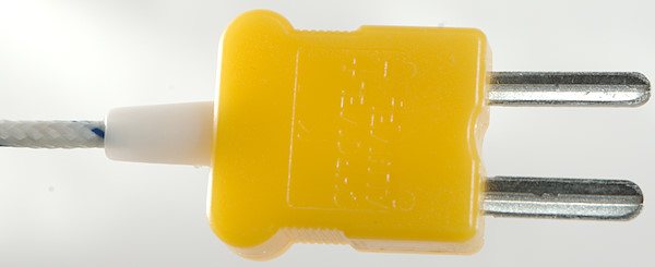
The two thermocouplers are standard K type with a standard K type plug.
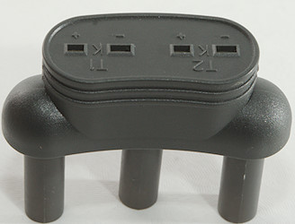
The thermocoupler adapter takes two standard thermocouplers and connect them to 3 terminals on the meter. T1 is volt input and common, T2 is mAuA input and common, in both cases common is the negative terminal.
This also means it is possible to use one thermocoupler with banana plugs as either T1 or T2.
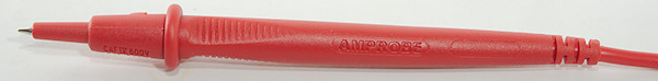
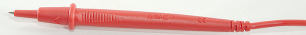
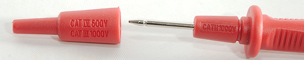
Probes are branded with Amprobe and has removeable tip covers.
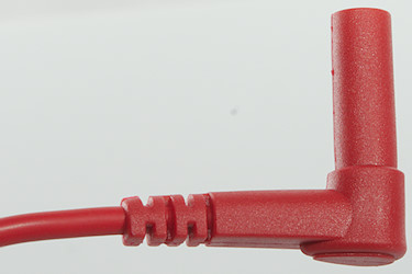
The plug is fully shrouded and standard probe plug size.
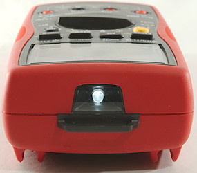
The meter has a led at the front for flashlight usage, it is behind a plastic window.
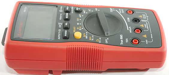
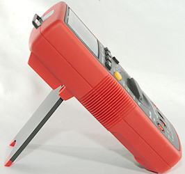
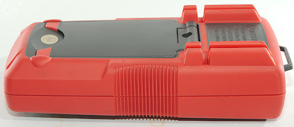
The tilting bale works very well, it is easy to extended and the rubber feet secures the meter do not slide around when pushing buttons or turning the range switch.
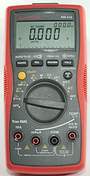
Display
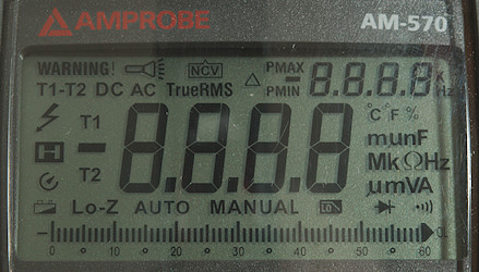
The above picture shows all the segments on the display.
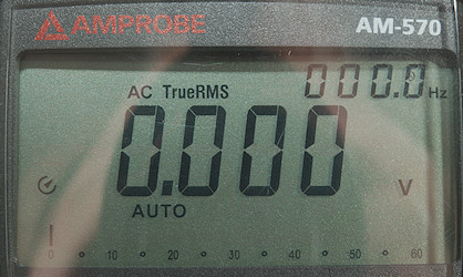
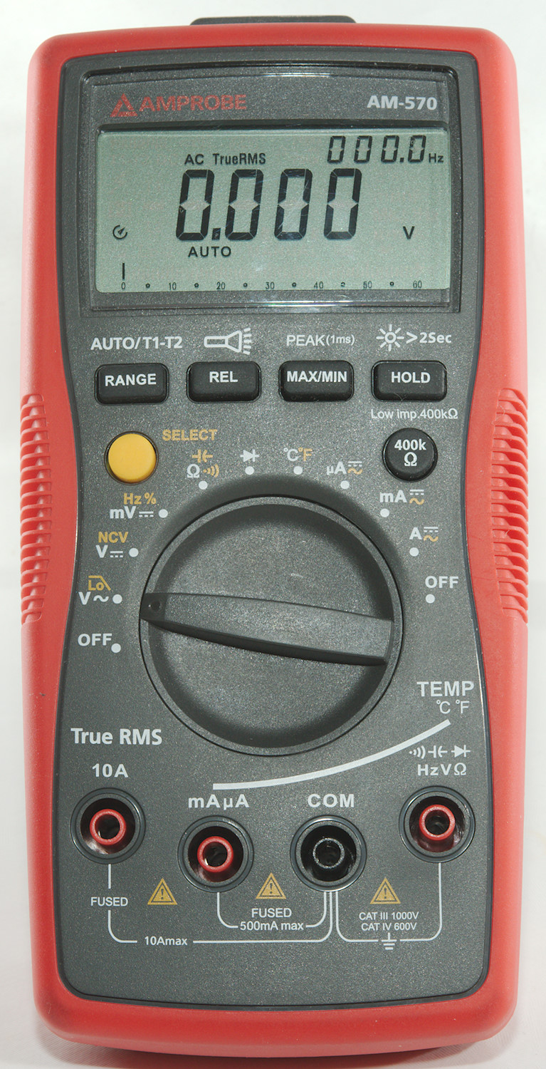
Typical display during usage, it will show the main number and what measurement is selected. In addition to this a secondary readout with frequency will be shows in AC modes, with max or min in max/min mode and with base value for REL modes. It is not used for dual thermocouplers.
NCV do not have its down display, it shows OL on the display and only indication of mains is the buzzer.
Functions
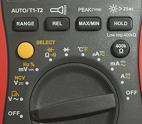
Buttons:
- Range: Will disable auto range and change range, hold down to activate auto range. This will also select between the two thermocouplers.
- Rel: Shows values relative to current value (The base value will be shown in the dual display), will also select manual range. Press again to disable. Hold down to turn flashlight on.
- Max/min: Select max/min mode, press to toggle between max and min in secondary readout, hold down to disable again. Holding the button down will enable peak detect, i.e. a very fast max/min mode.
- Hold: Freezes the display, hold down for backlight.
- Select (Yellow): Select the ranges printed with yellow
- 400kohm: Hold down for loading input terminals, the beeper will sound while this button is activated and display will show Low-Z.
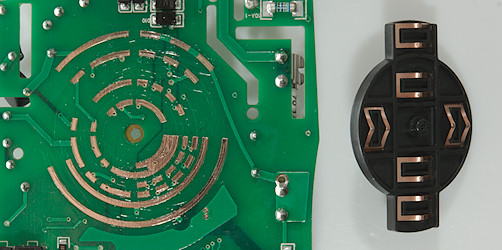
Rotary switch:
- Off: Meter is turned off
- VAC: Show AC voltage, use yellow button to activate a low pass filter.
- VDC: Show DC voltage, use yellow button for non-contact voltage mode.
- mV: Millivolt DC, use yellow button for frequency and duty cycle.
 : Resistance, continuity and capacitance.
 : Diode.
- °C°F: Temperature, use yellow button for C/F and range to select between T1, T2 and T1-T2
- uA: Microampere current, use yellow button to select AC
- mA: Milliampere current, use yellow button to select AC, the burden voltage is very bad in the high mA range.
- A: Ampere current, use yellow button to select AC
- Off: Meter is turned off
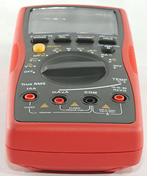
Input
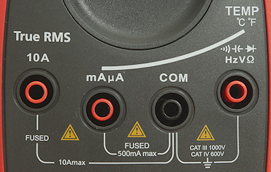
- A: High current, maximum current is 10A
- mAuA: The lower current ranges, this is also input for T2 temperature sensor.
- CON: The common terminal for all ranges.
- xxx: All other ranges.
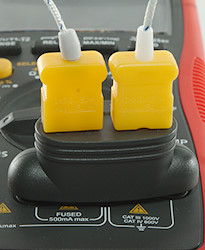
The thermocoupler adapter with two thermocouplers.
Measurements
- Volt and frequency
- Frequency counter is always displayed in AC ranges
- Frequency input can handle a DC offset of about ±3.5 volt, but requires a few seconds to compensate for it.
- Frequency input requires about 0.2Vrms before it works.
- At 1Vrms input frequency range is from 4Hz to 50MHz
- At 2Vrms input frequency range is from 4Hz to 60MHz
- Duty cycle works from 0.2% to above 99% at 100kHz with 10Vpp, precision is within 0.4.
- Duty cycle works from 10% to above 90% at 10kHz with 1Vpp, precision is within 4 most of the time.
- 1 VAC is 5% down at 3kHz (RMS will not work at the frequency).
- 1 VAC with LPF is 5% down at 570Hz (RMS will not work at the frequency).
- Peak needs about 1.5ms to capture a voltage and works for both AC and DC.
- Max/min needs about 120ms to capture a voltage.
- If there is a large DC voltage with AC selected, it will show 0 (or a low value).
- Input impedance is 10-11Mohm on DC and AC
- The mV range is only for DC and is 3-10Mohm below 3.5 volt, above it drops to a few kohm
- Pressing the 400kohm button will put 390kOhm across the voltage input in all ranges.
- Bargraph is faster than number display (Rated 20 times/sec).
- Rated overload protection is 1000VDC on DC range and 1000VAC on AC range
- Frequency input resistance is above 1Mohm below 4 volt, but then drops to 3kOhm
- Current
- Frequency counter is always displayed in AC ranges
- uAmA fuse is 0.5A/1000V 6.3x32mm
- A fuse is 15A/1000V 10x38mm
- There is an audible alarm when current is above 10A.
- Burden voltage is very bad at high mA, it is 2.1V at 590mA (Use 10A range to avoid this).
- There is an audible warning and blinking warning text when using non current ranges with a probe in mAuA or A input.
- Ohm, continuity, diode and capacitance
- Ohm needs about 3.2s to measure 100ohm
- Ohm is -1.2V open and -0.85mA shorted
- Continuity is very fast (About 4ms).
- Continuity beeps when resistance is below 10ohm and stays on til 50ohm
- Continuity is -3.3V open and -0.85mA shorted
- Diode range uses 3.1V, max. display is 2.900V at 0.07mA, max. current is 1.0mA shorted
- 600uF takes about 6 seconds to measure.
- Rated overload protection is 1000V peak
- Miscellaneous
- When temperature probe is outside range it will be reported as "open"
- Current consumption of meter is 7.5mA and 2mA extra for AC (24mA with backlight in DC, 21mA with flashlight in DC, in AC with backlight+flashlight it is 39mA)
- Meter works down to 3.4V where display starts to fade and is invisible at 2.1V, battery symbol show at 7V.
- A 5V reading will change 2 count from 9V to 2.1V
- Backlight and flashlight start to fade at 3.6V
- The meter is fast to show correct reading.
- Viewing angle is good
- Display updates around 3 times/sec
- Backlight and flashlight will turn off with the automatic power off, not before.
- Will automatic turn power off in about 15 minutes.
- Banana plugs and standard probes is difficult to fully insert on the mAuA and A ranges, but works fine on V input.
- The meter has a warning beep for wrongly inserted probes in the two ampere terminals.
- Generally the precision is nearly "spot on", i.e. usual only a few counts out.
- Weight is 370g without accessories, but with batteries.
- Size is 189 x 89 x 50mm.
- Probes
- Probe resistance 24mOhm for one.
- Probe wire is soft and 88cm long.
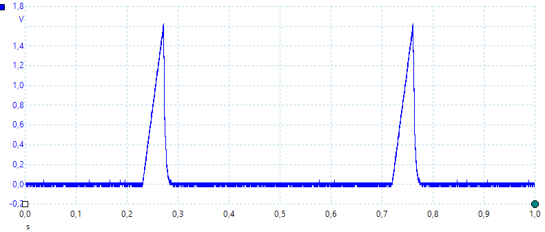
A look at the capacitance measurement waveform.
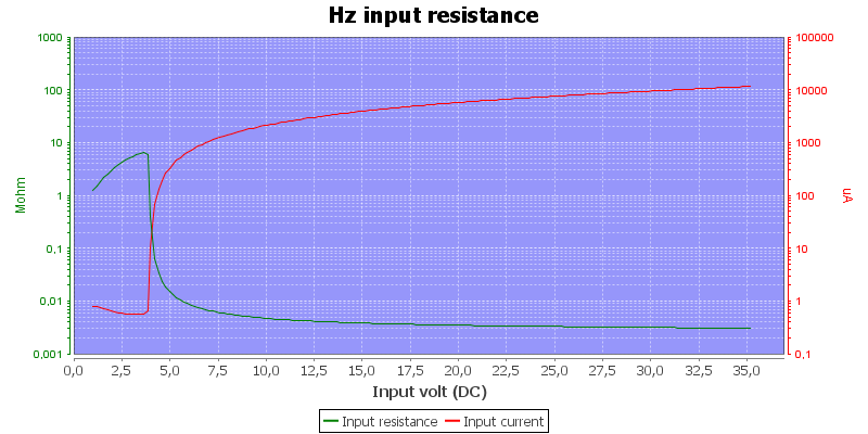
Frequency input resistance.
Actual burden voltage at 6mA is 0.96 volt an internal diode bridge reduces the burden voltage at higher currents.
Actual burden voltage at 600mA is 2.05 volt an internal diode bridge reduces the burden voltage at higher currents.
With high DC voltage present the AC range will not show low AC voltages.
NCV only use buzzer as indication, not light or display.
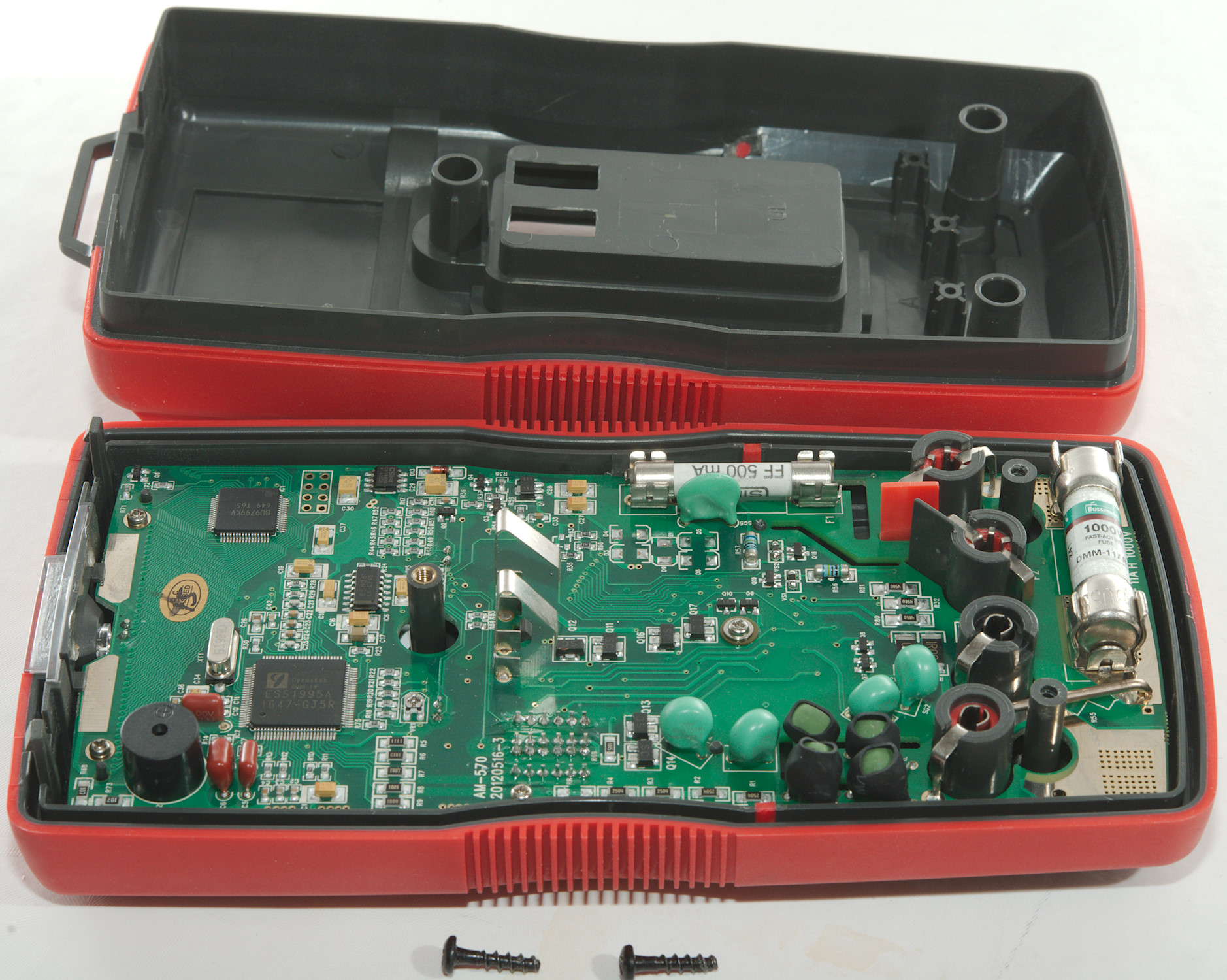
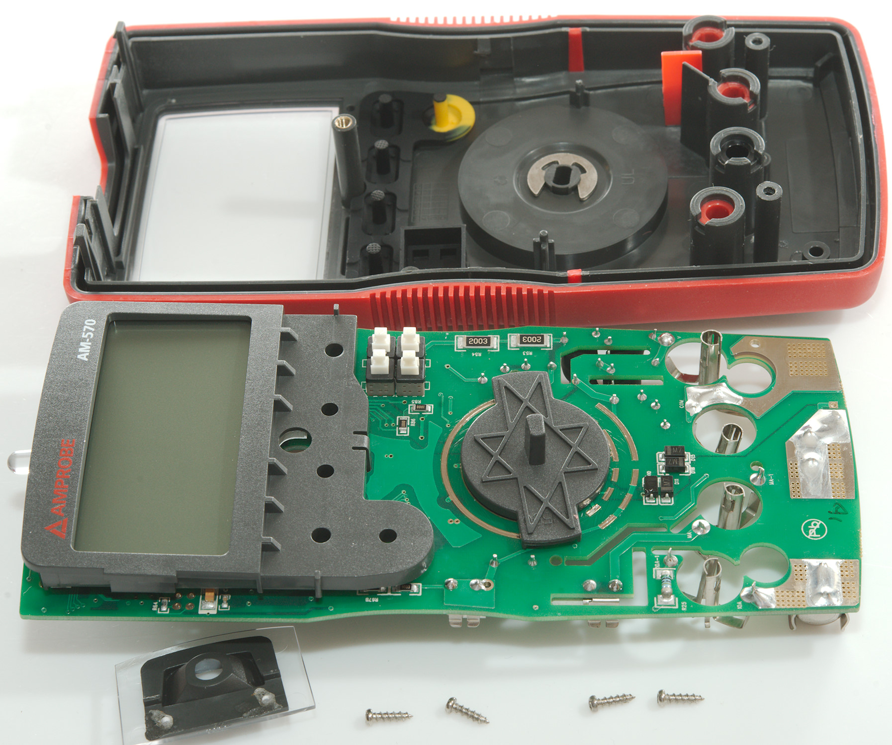
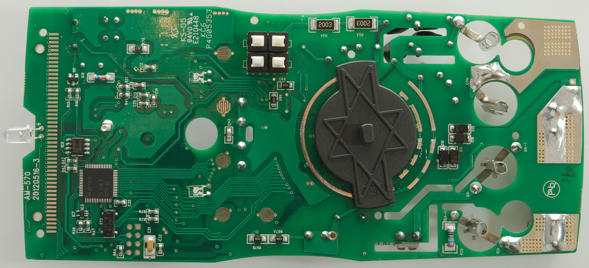
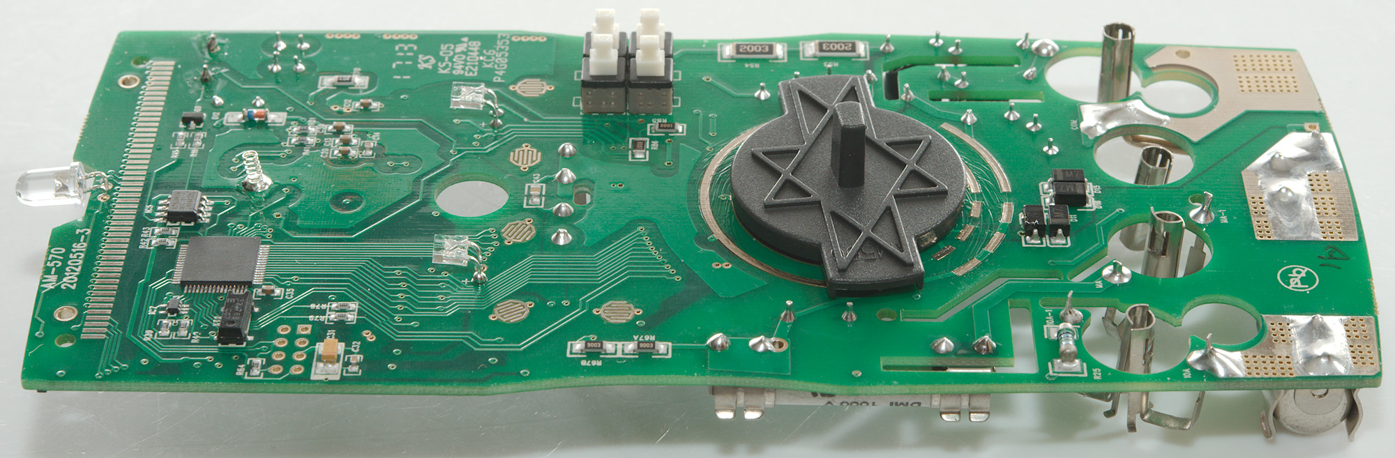
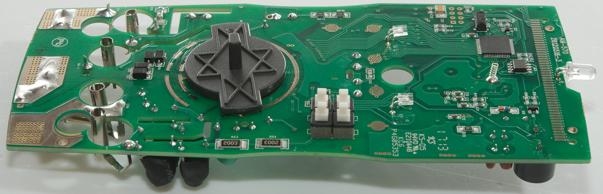
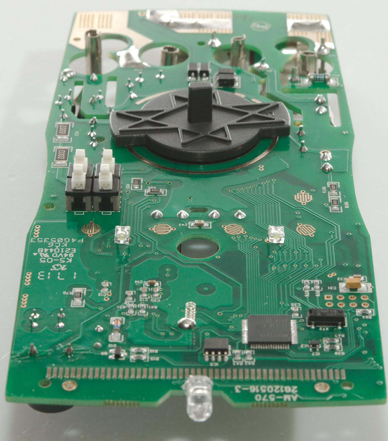
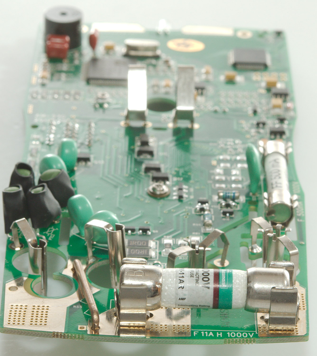
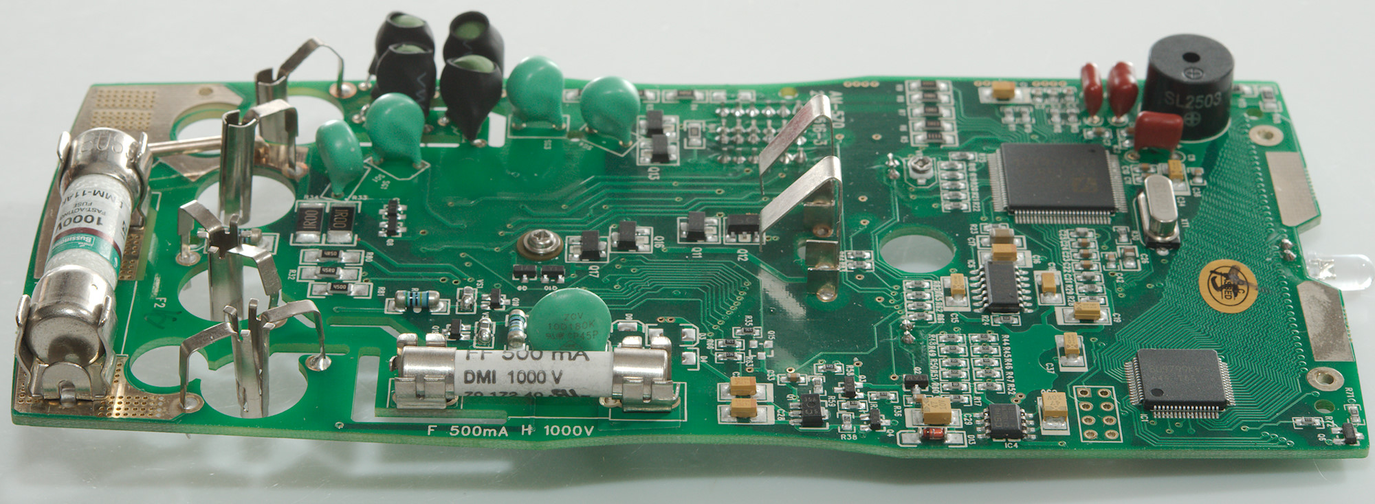
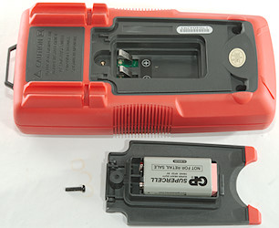
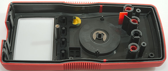
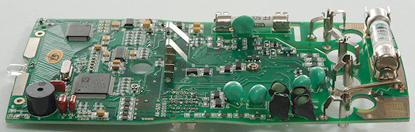
Tear down
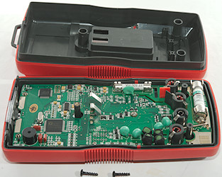
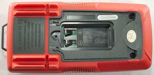
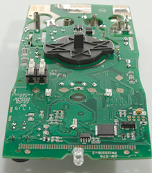
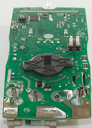
3 screws (One was for the battery cover) and the back could be removed.
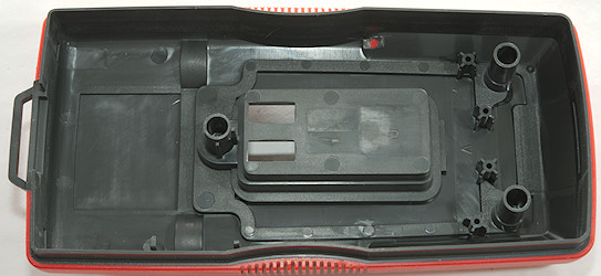
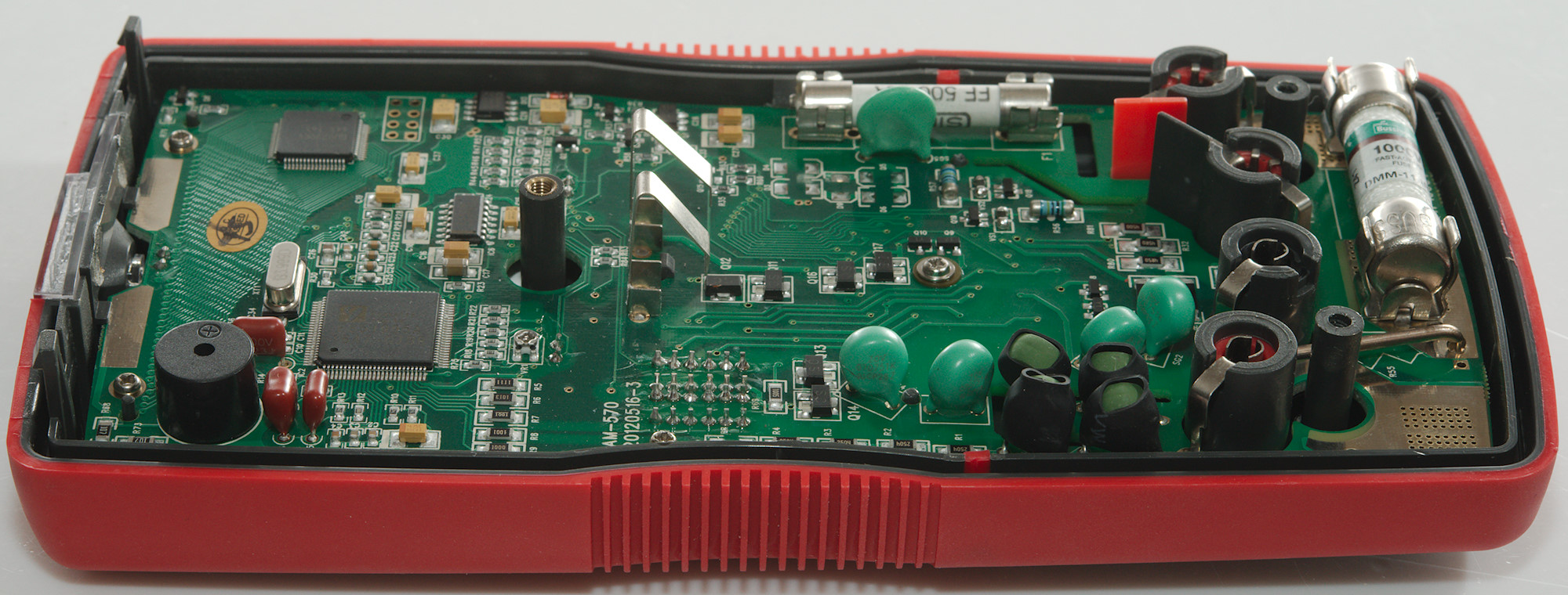
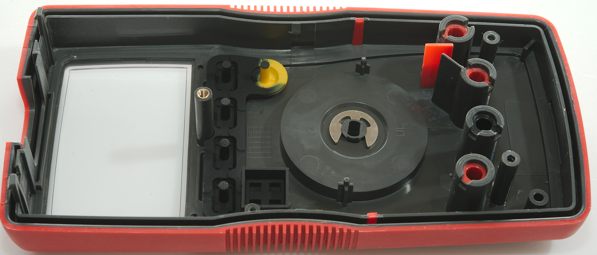
The circuit board is shaped to follow the shape of the box. In addition to the screws there are two clips at to keep the circuit board in place.
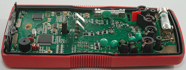
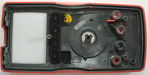
Four screws and I could take the circuit board out, the input terminals was rather difficult to get out.
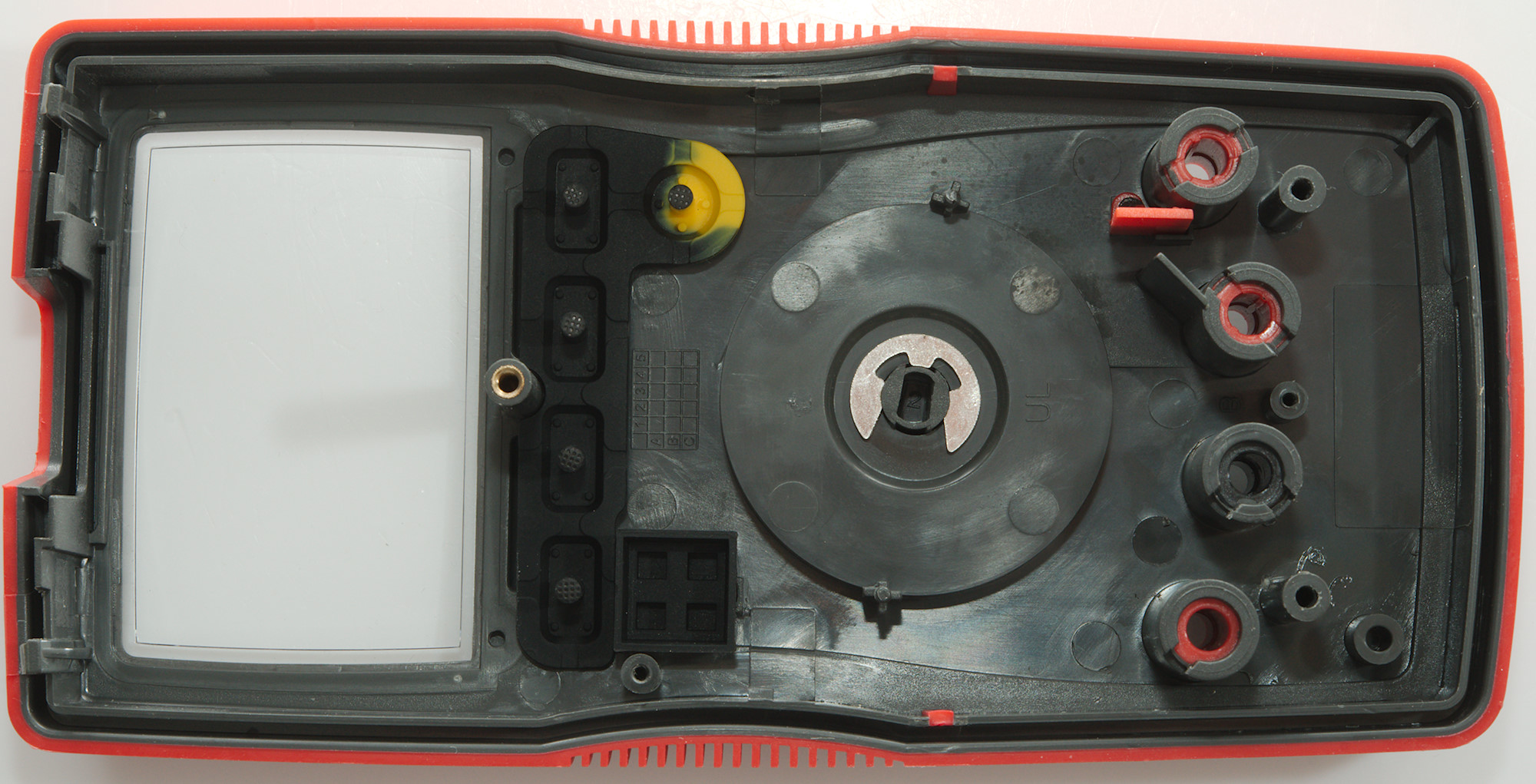
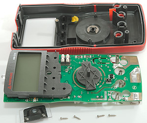
Only the two screws was necessary, the two at the top was only for the display cover.
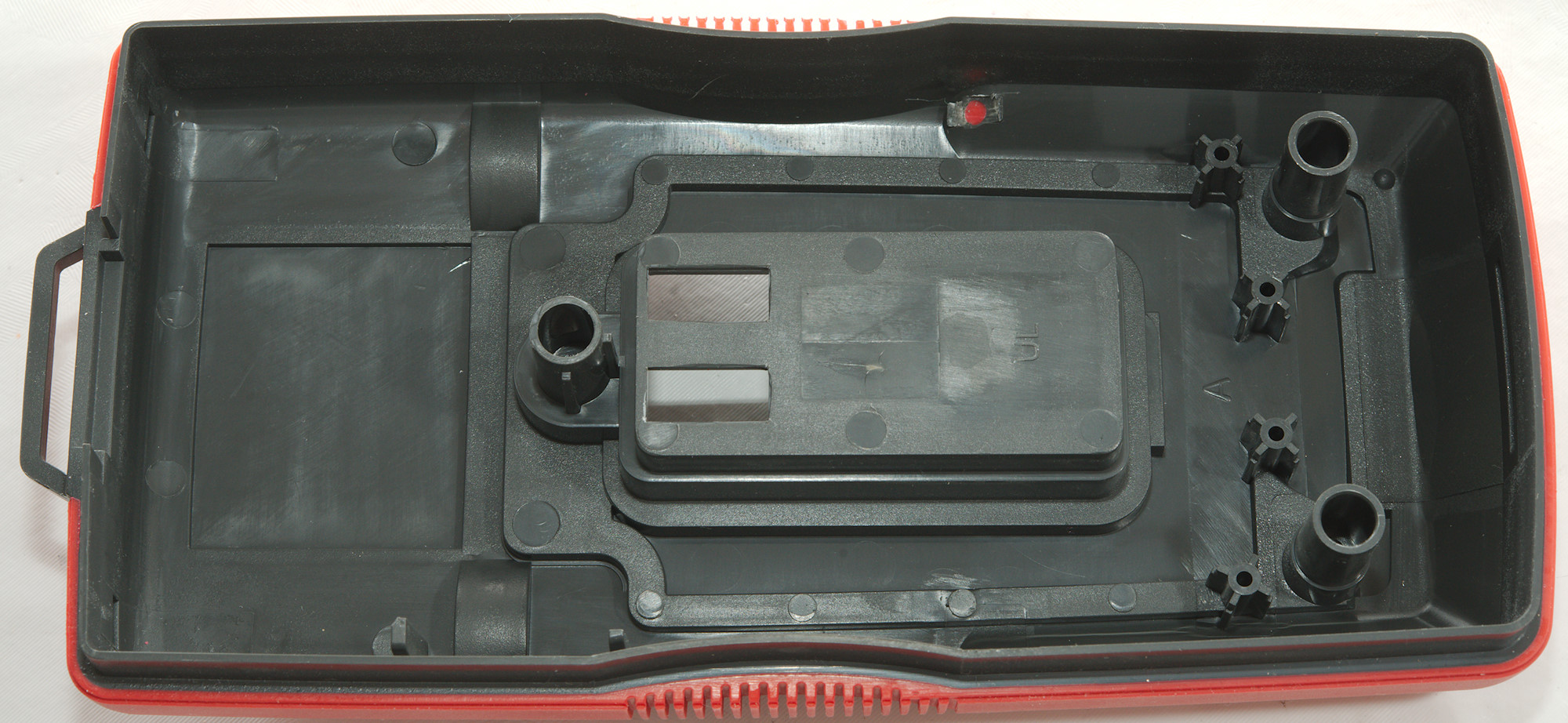
There is some shielding in the plastic for the ampere input. It matches slots in the circuit board.

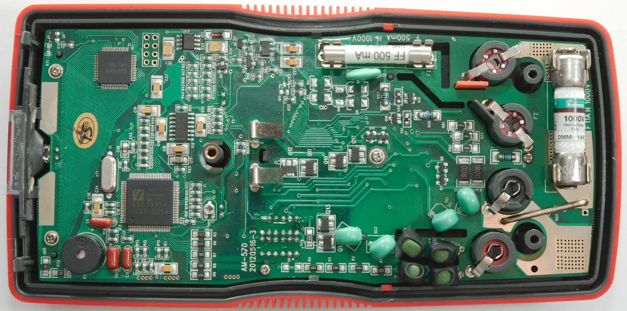
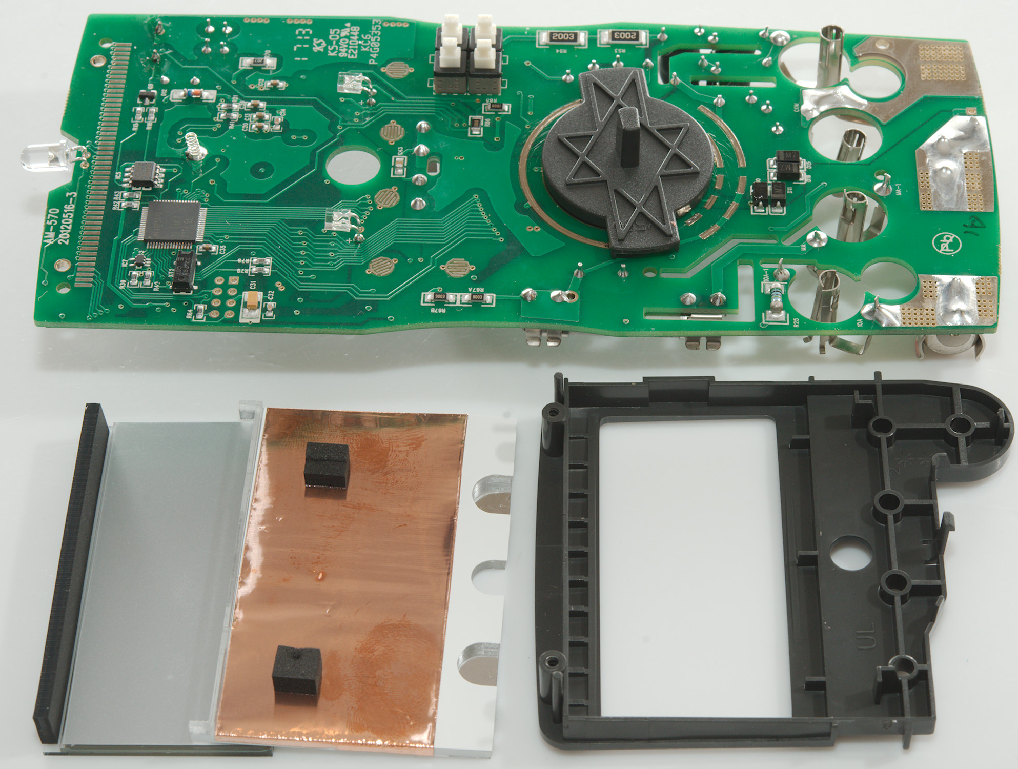
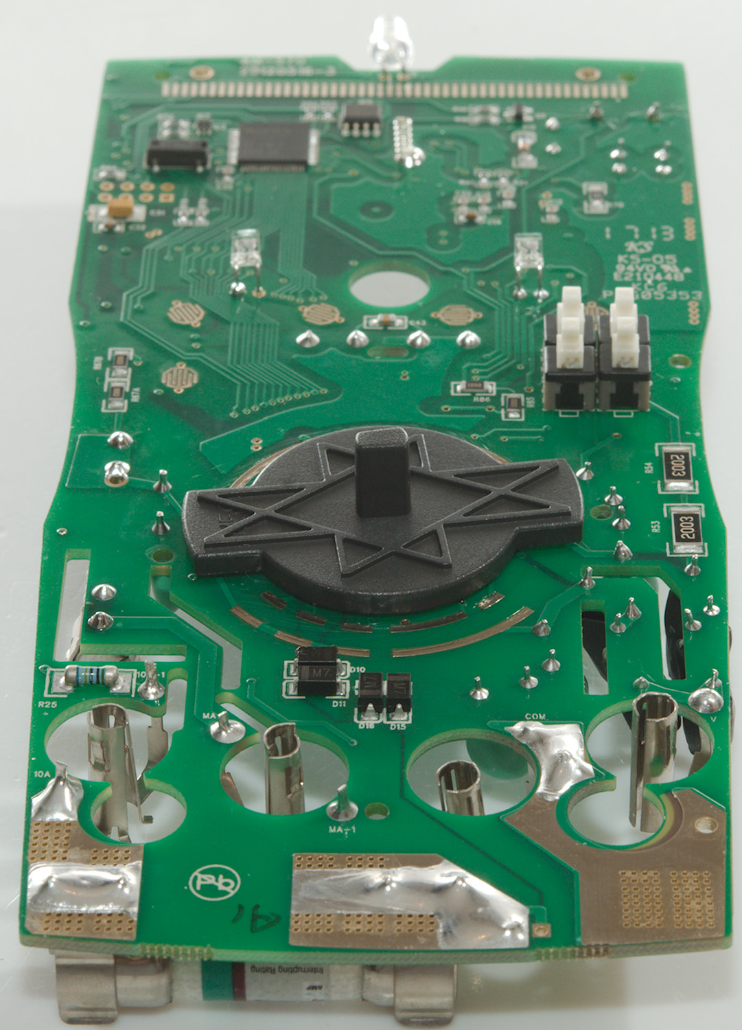
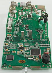
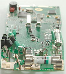
There is some electronic below the display.
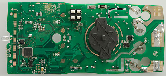
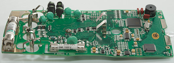
There protection for R80 in the current shunt (D10, D11, D15, D16) is on this side. The 10A sense line has a series resistor (R25 5Mohm). The 400kohm switch is 4 switches and two resistors (R53, R54, 2x200K) in series.
There is two leds for background light to the LCD display.
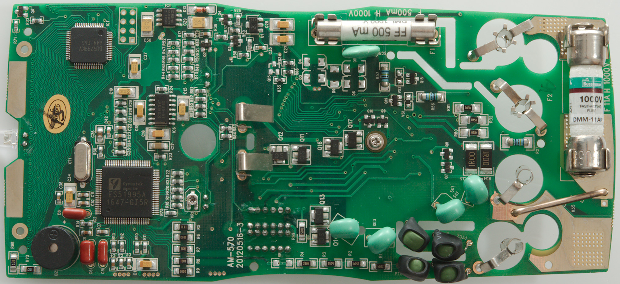
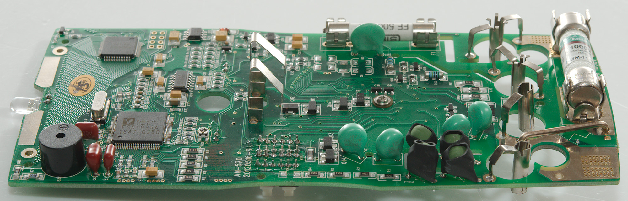
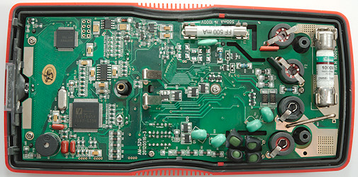
The big chips is a microprocessor (MSP430F5310 with 32K program memory and 6K ram) and there is a EEPROM (IC5: ATMLH838).
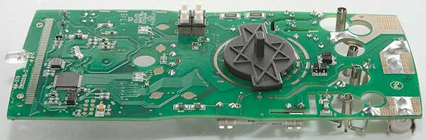
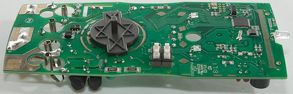
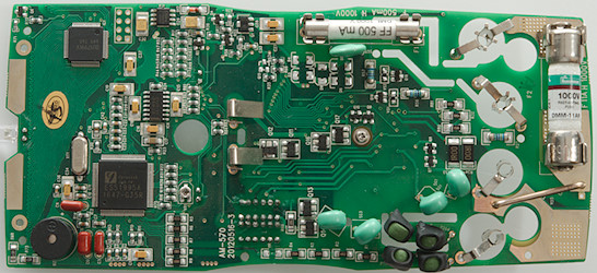
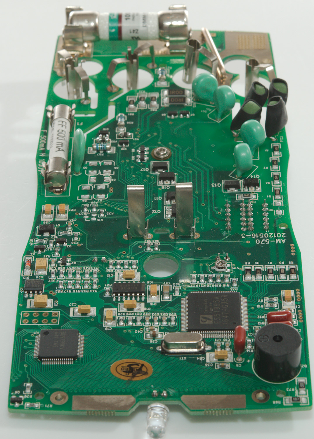
There is a lot of input protection on this meter. Two sets of double PTC's (PTC1, PTC2, PTC3, PTC5) followed by dual MOV's (SG1, SG1, SG3, SG4) and then lots of transistors pairs, some of them with fairly large transistors (Q7, Q8 & Q9, Q10 & Q11, Q12 & Q13, Q14 & Q16, Q17). The MOV (SG5) besides the 0.5A fuse is probable protection for T2 input). The 10Mohm input is made from four resistors (R1, R2, R3, R4: 4x2.5Mohm).
The full current shunt protection (D3, D4, D5, D6, D9) is missing
The actual current shunt is a bit special, it uses a couple of resistors in series and parallel (R33, R34: 2x1ohm in parallel, R80, R32, R81: 4.5ohm, 45ohm, 450ohm in series). This makes the mA current shunt 0.5ohm + 4.5ohm with diodes and explains the very bad burden voltage. In the uA shunt the diodes clamps the 450ohm resistor.
The two large chips are a DMM frontend (IC2: ES51995A: 6000 count) and a LCD driver (IC1: BU9799KV). The frontend has an external True RMS converter (IC6: ES636: 200 segment driver). There is also a charge pump (IC4: CAT550) making a negative voltage from the internal 3.5V that is made with a linear regulator (Q1).
At the top of the circuit board is the NCV antenna
Conclusion
This is a fairly advanced meter with many functions and most of the working perfectly, but I do not like the uA and mA ranges, the burden voltage is way to high and I do not have confidence in the protection, because the diodes are missing (This circuit is from the DMM chip datasheet, there is also a circuit that requires an OpAmp and gives low burden voltage), the meter is also missing the low A range. The NCV is audio only, this is not a good solution.
Except for the above the meter is fairly good with lots of extra functions like: flashlight, Peak, LPF, dual temperature inputs, Low-Z.
Notes
How do I review a DMM
More DMM reviews
About thermocouplers