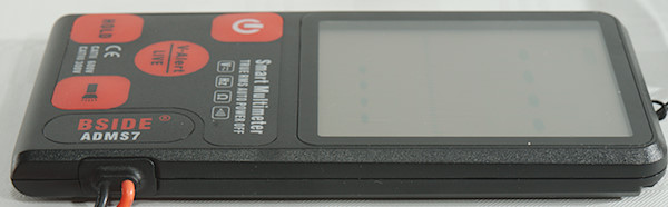
DMM BSide ADMS7
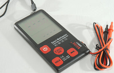
This meter is a very simple meter with most functions automatic. It has a very large and easily readable display.
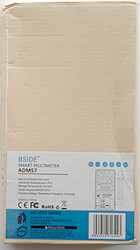
I got it in a brown neutral cardboard box with some stickers on.
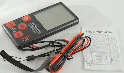
It included the DMM and a instruction sheet.
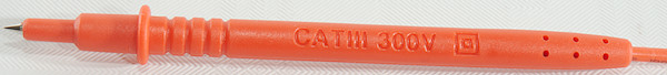
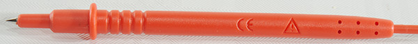
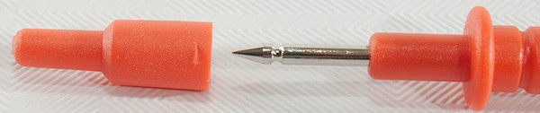
Probes are branded with BSide and has removable tip covers. There is a CAT III 1000V rating on the cover, but none on probe.
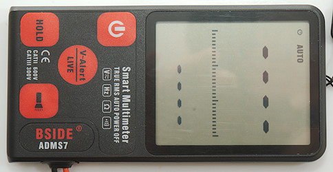
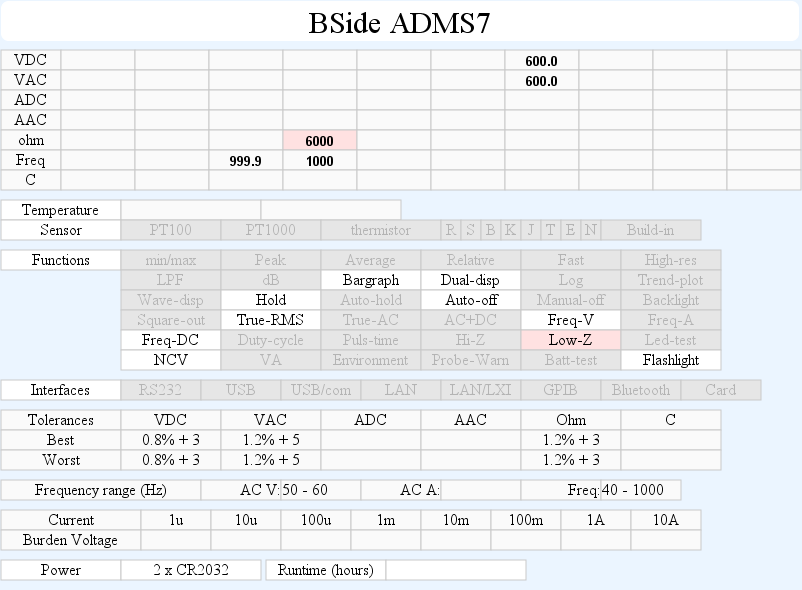
Display
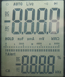
The above picture shows all the segments on the display, not all are used.
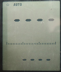
Display when idle, it will show AUTO and some bars.
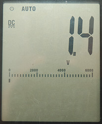
When measuring DC voltage or ohms it will show the value and the range.
The bargraph is scaled up to 6000, this is only valid in ohms, in volts it must be read as 600.0.
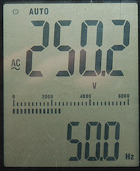
In AC mode the lower display will show frequency.
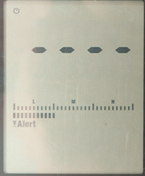
The V-Alert is the usual NCV and used the bargraph to show the electric field strength. There is only 3 steps with voltage, the above picture is the first step, it uses sound in addition to the display.
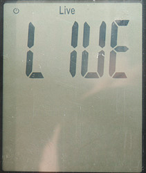
The live function will detect mains voltage with on one connection and then show LIVE, including sound.
Functions
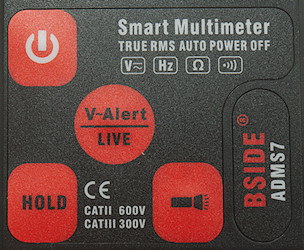
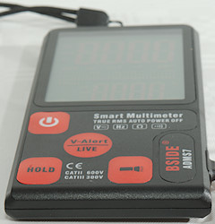
Buttons:
 : A press on this button will turn the meter on or off. Both on and off only requires a short press.
- V-Alert/Live: This button will select the two detection function, it has some sort of history function and may start with either V-Alert or LIVE
- Hold: Freezes the display.
 : A short press will turn on the flashlight.
Input
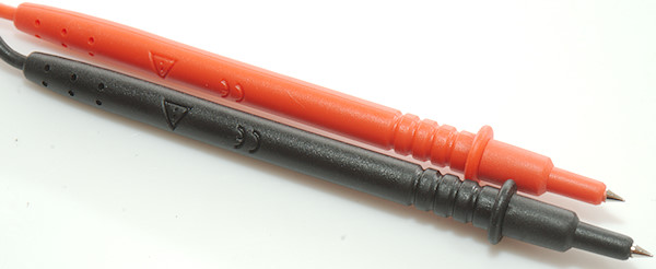
The probes are not replaceable.
Measurements
- Volt and frequency
- Frequency counter do not require a zero crossing.
- At 1Vrms input frequency range is from 36Hz to 550Hz
- At 7Vrms input frequency range is from 36Hz to 1kHz
- 7 VAC is 5% down at 1.2kHz (RMS will not work at this frequency).
- A combined AC+DC voltage is listed as AC with the a total value, but not the RMS value.
- Input impedance is 1Mohm on DC and AC
- Meter will measure DC voltage above 0.3 volt for positive and 0.7V for negative.
- Meter will measure AC voltage above 0.9 volt and be very confused below.
- Rated overload protection is 600V DC or AC
- Current
- The meter cannot measure current.
- Ohm, continuity, diode and capacitance
- Ohm needs about 0.7s to measure 100ohm
- Ohm/Continuity is -0.8V open with -2V spikes) and -0.03mA shorted
- Continuity is slow (About 300ms).
- Continuity beeps when resistance is below 30ohm
- Rated overload protection is 600V DC or AC
- Miscellaneous
- Current consumption of the meter is 2.3mA with backlight it is 32mA (14mA at 4V)
- Current consumption when off is 0.026mA, this means the batteries will last about a year.
- Meter works down to 2.4V where it shows random values, it turns off at about 1.8V, battery symbol show at 3.6V.
- Meter readings are stable until 3.0V
- Flashlight fades with voltage and is very dim at 2.5V
- The meter may need one or two update to show the final value.
- Viewing angle is good
- Display updates around 2 times/sec
- Flashlight turn off after about 30 seconds.
- Will automatic turn power off in about 3 minutes.
- Weight is 112g without accessories, but with batteries.
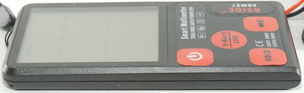
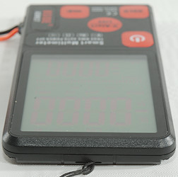
- Size is 136.9 x 73 x 12.7mm.
- Probes
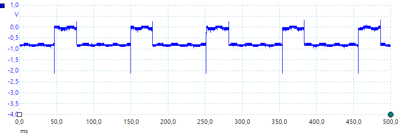
The sense voltage when checking for resistance.
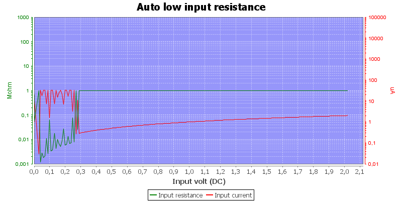
When supplying a external DC voltage it will turn the checking voltage off above 0.3V and show a DC voltage.
The input resistance is 1Mohm
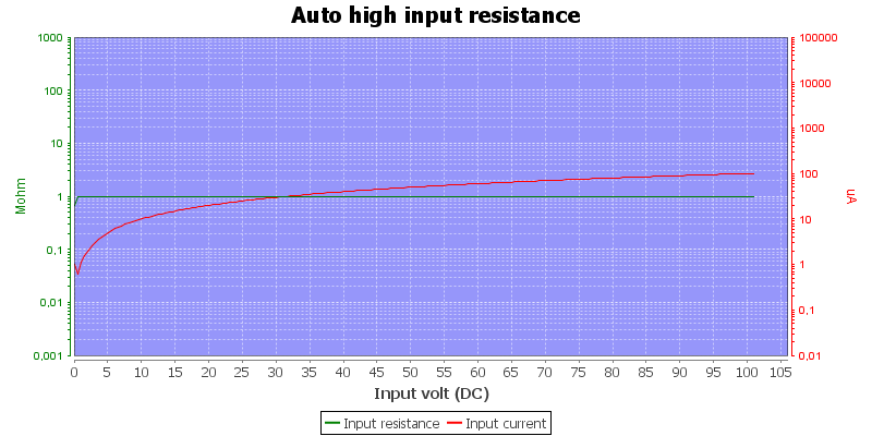
The 1Mohm is the same all the way to 100V.
Ohm has a 6-8ohm error.
It will mark a voltage as AC if it contains DC with some ripple, but it will not necessary show the RMS value.
The 1Mohm input impedance is close to being a Low-Z function.
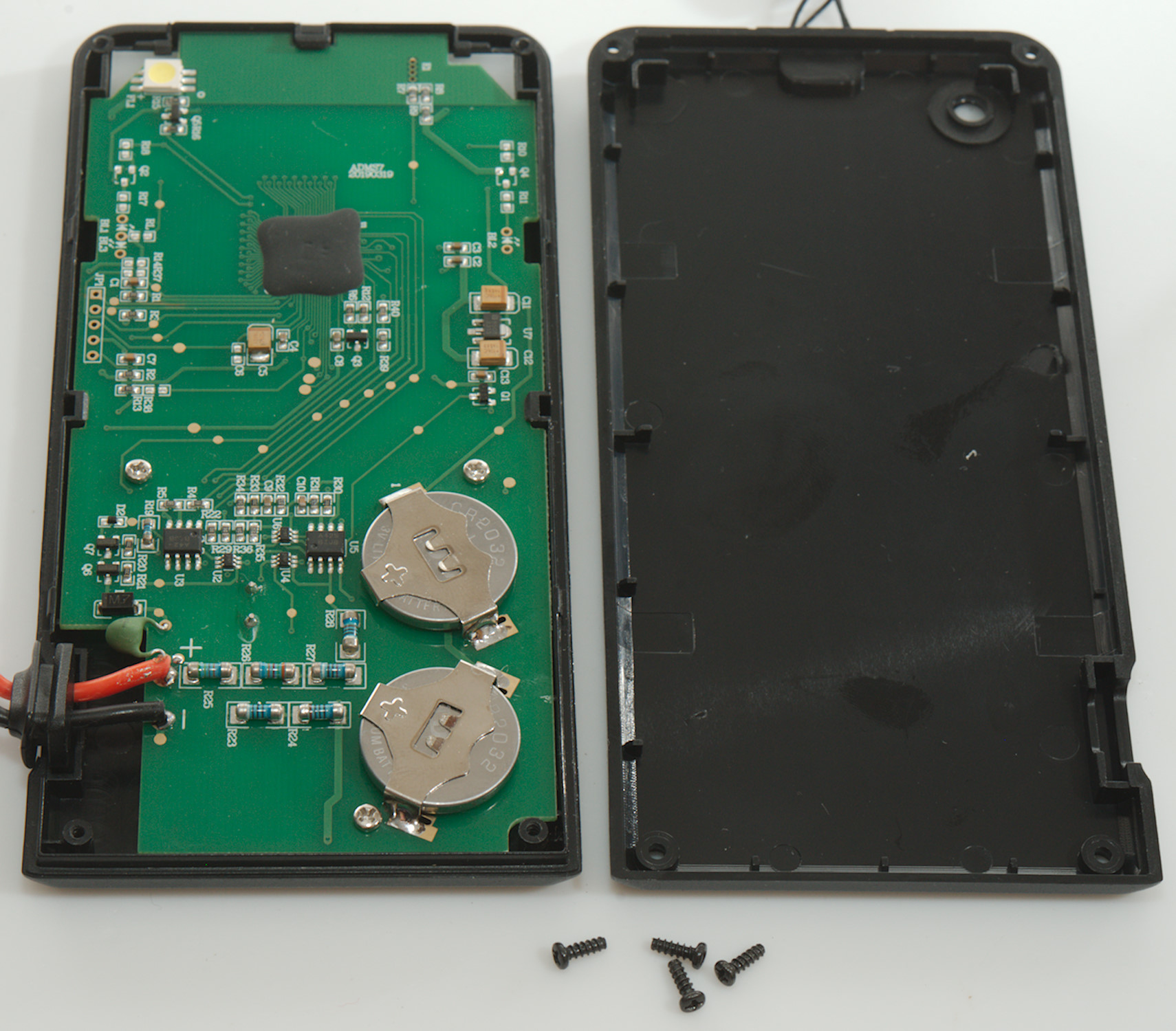
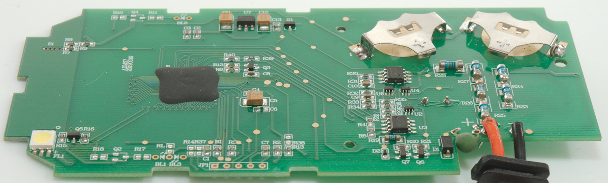
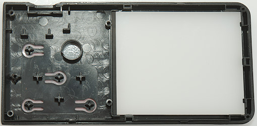
Tear down
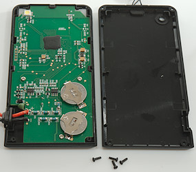
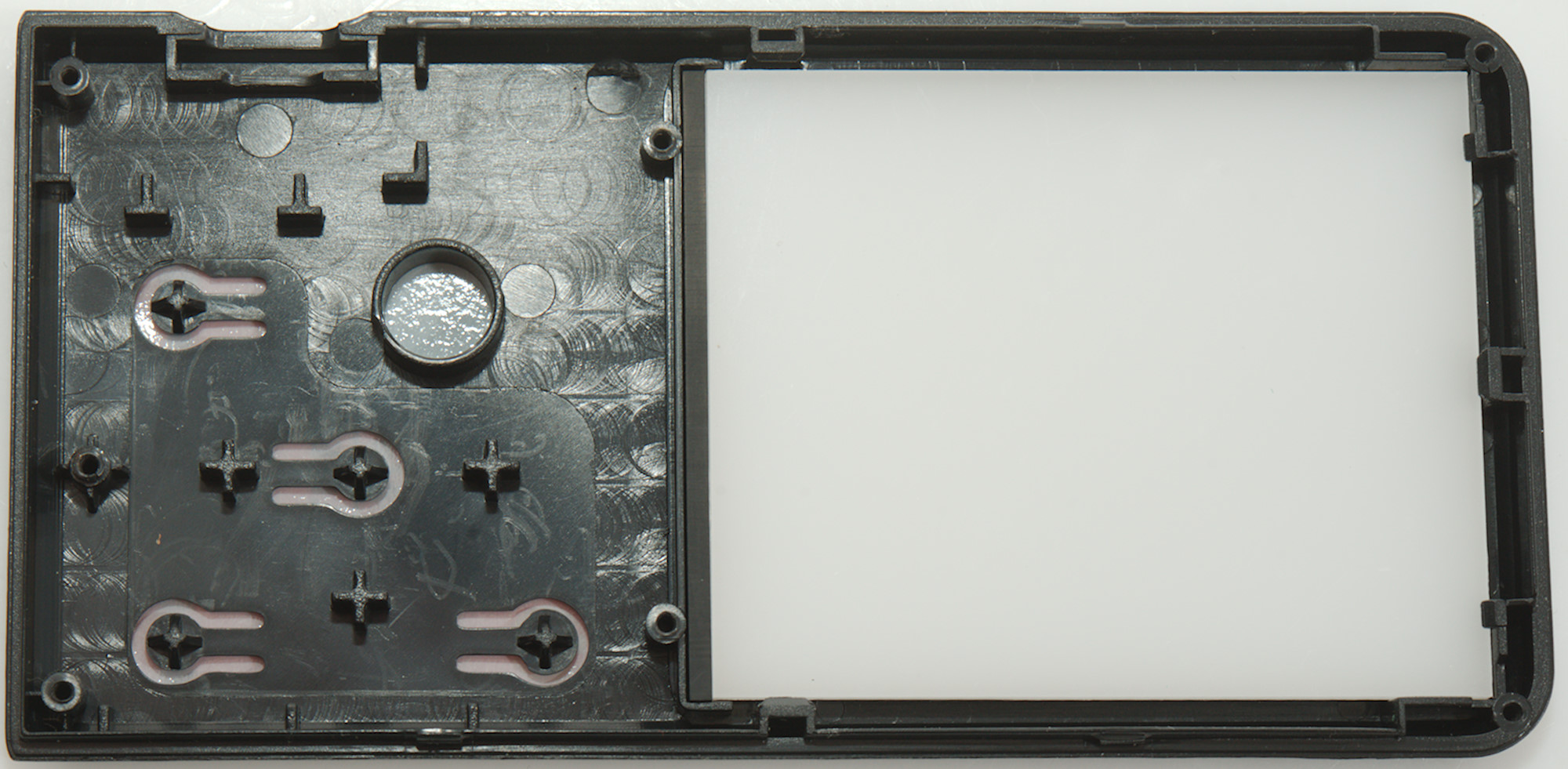
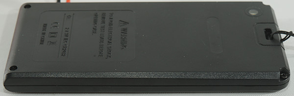
To open the meter I had to remove four screws. The manual specify AAA batteries, but it is CR2032.

The leads uses the typical rubber grommet to provide strain relief and protection from sharp bends.
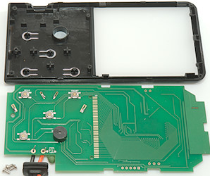
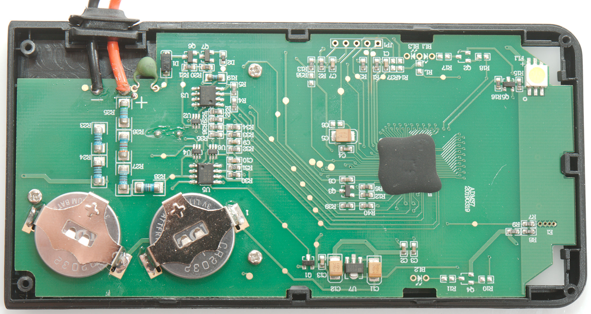
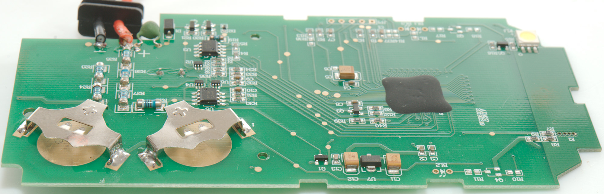
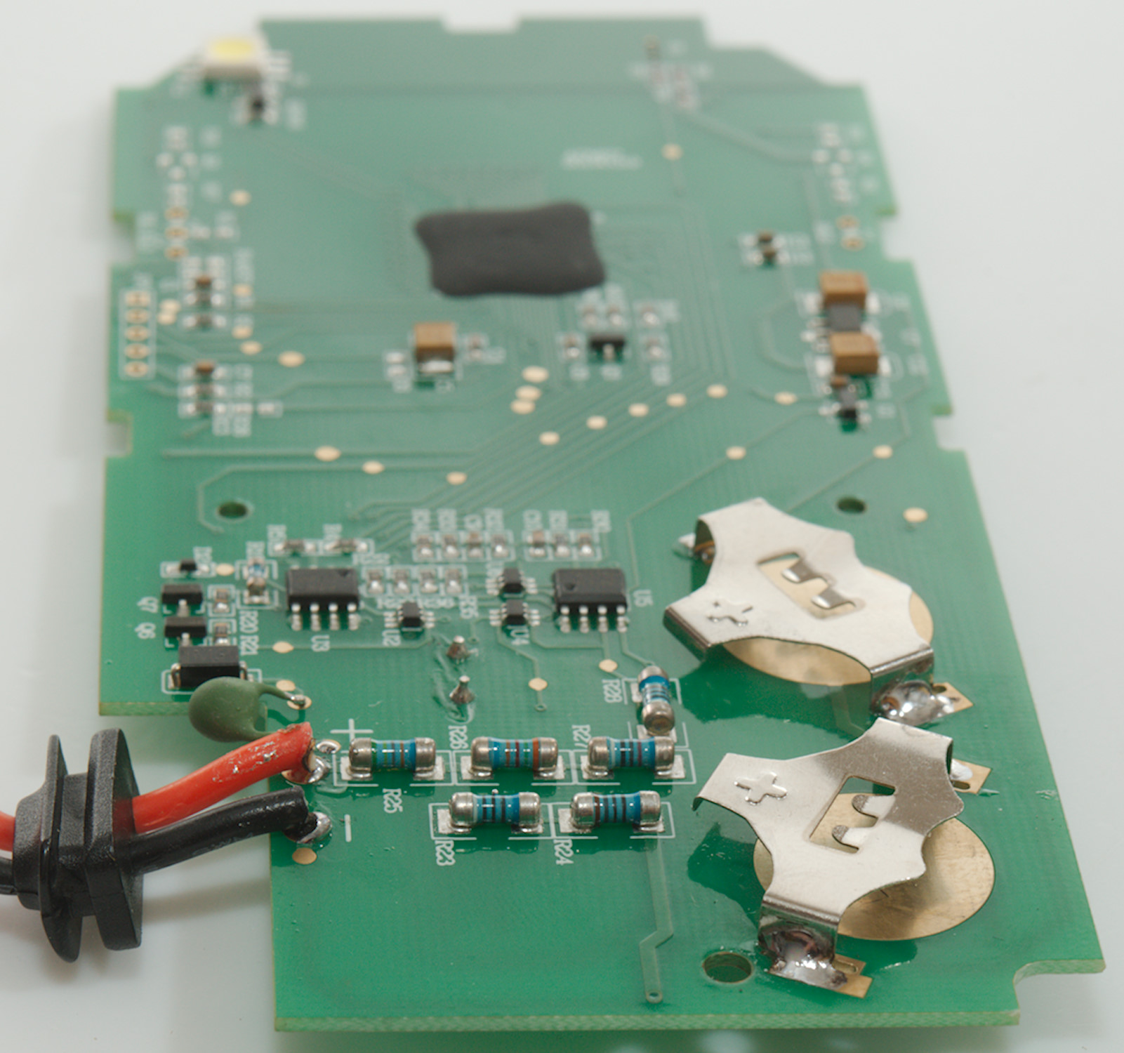
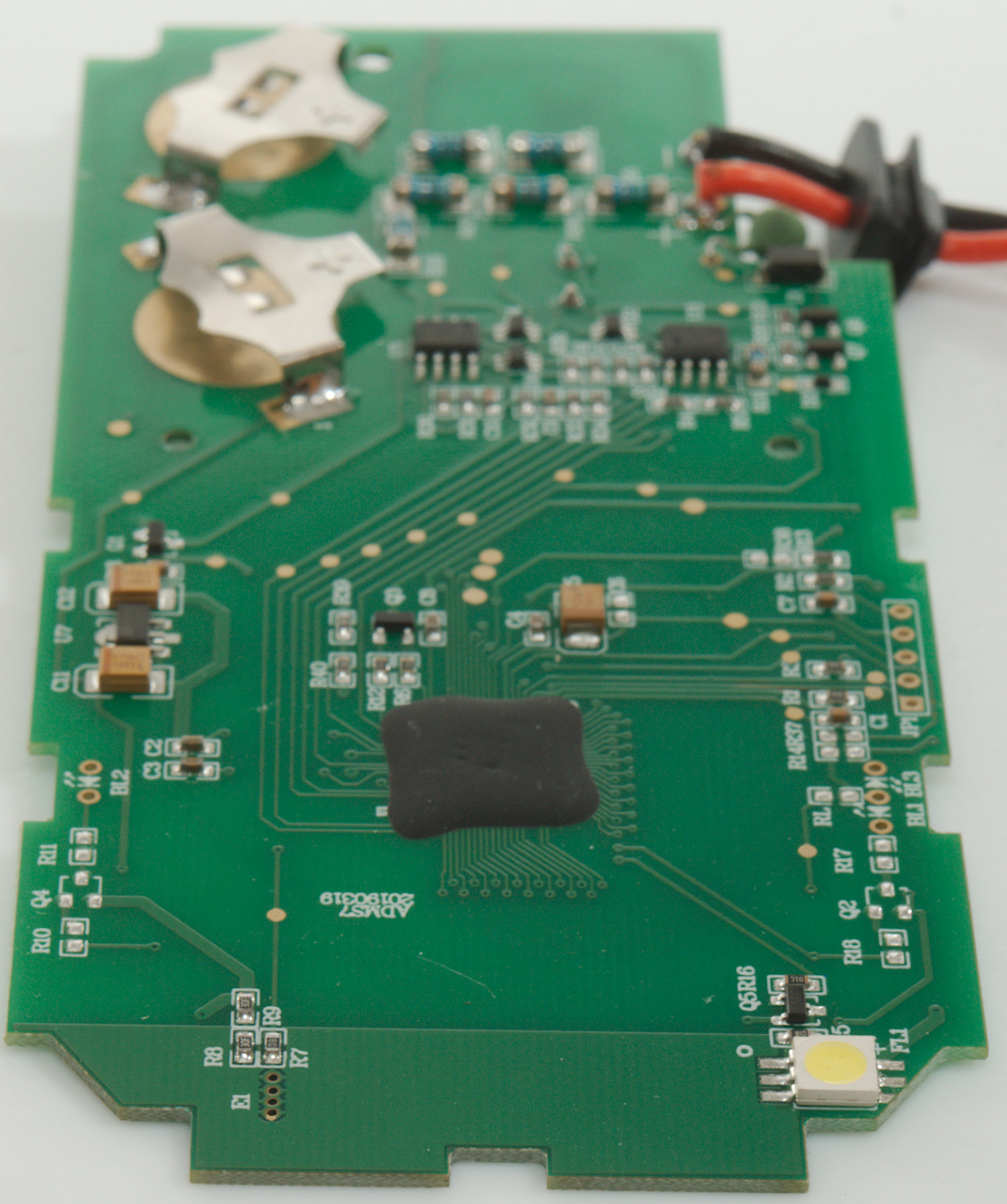
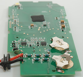
I had to remove 3 more screws to get the circuit board out.
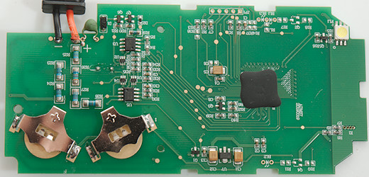
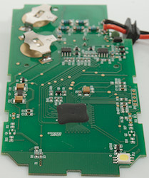
The input has two paths, one through a couple of resistors (R25, R26, R27, R8: 547kOhm, 352kohm, 90kOhm, 9kOhm -> 998kOhm) and another path through a PTC, diode (D1) and some transistors (Q6 & Q7), it looks like the transistors is used to enable and disable the ohm range. There is two types of IC's to handle the automatic range switch, they are MUXes (U2, U4, U6: Probably SN74LVC1G3157) and OpAmps (U3 & U5: Probably LMV358).
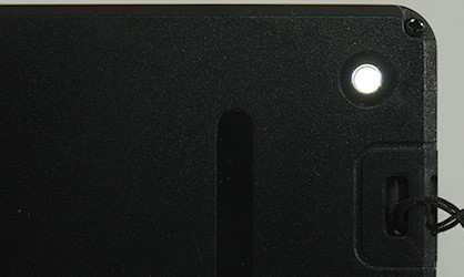
There is a NCV antenna at the top of the board, next to the flashlight led (FL1), that is a square led with a control transistor (Q5) next to it. The power supply chip (U7: 8503-33: 3.3V) is between two decoupling capacitors (C11 & C12).
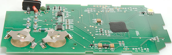
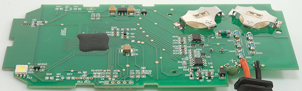
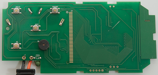
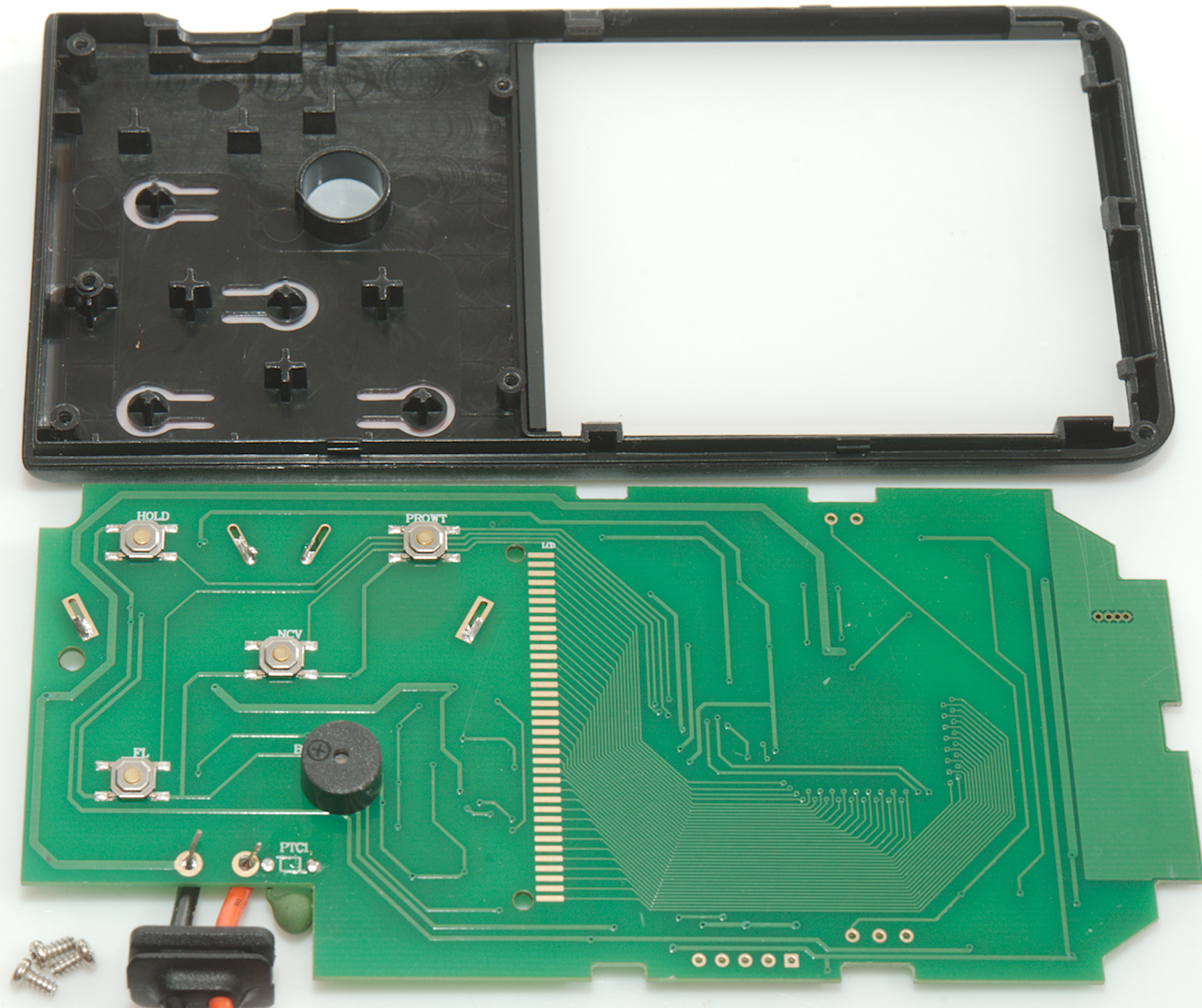
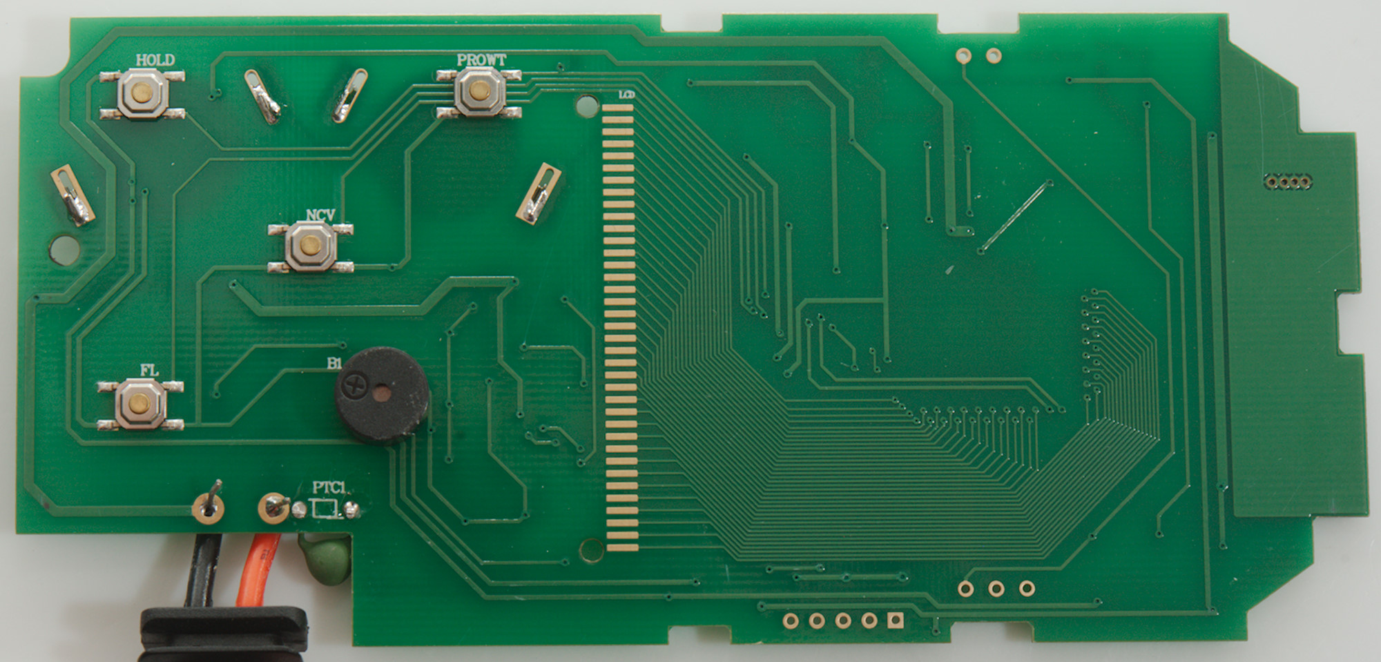
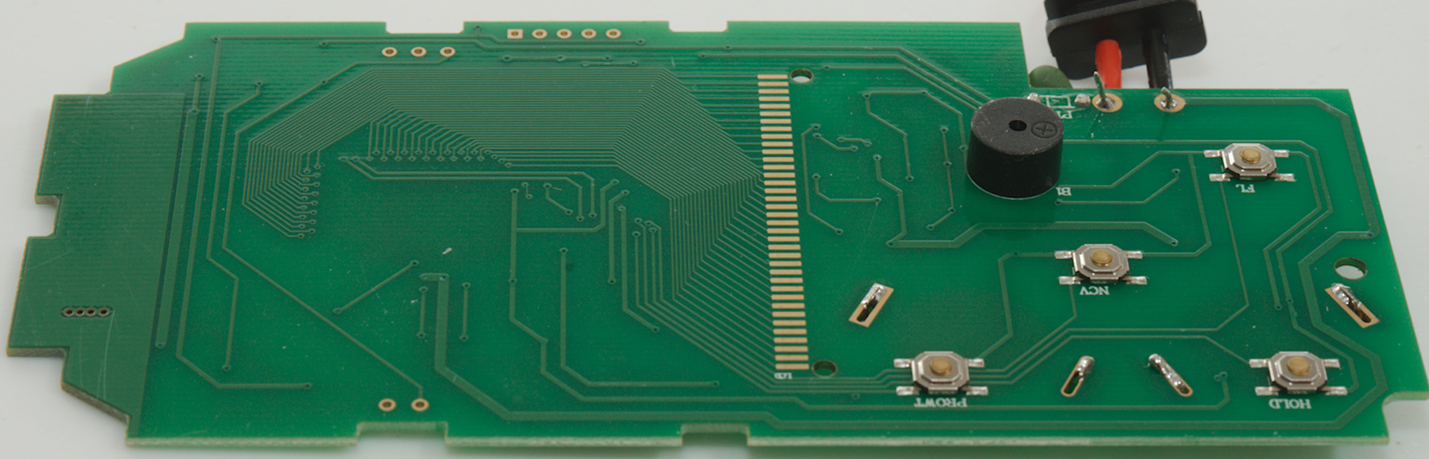
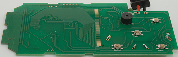
The meter uses real switches and has a buzzer on this side.
Conclusion
As usual the safety is on the low side
I like the large display on the meter, but that is about the only thing.
This is a very simple meter without ranges, it works and may be fine for for a rough and simple check, but it cannot do much more. Because it only has one range VDC, one VAC and one ohm range, it only has decent resolution in a fairly limited range of values. The true RMS is a bit doubtful, when it cannot show a combination of AC+DC correctly. The current consumption when off is way to high.
Notes
How do I review a DMM
More DMM reviews
About thermocouplers