Panasonic BQ-CC75
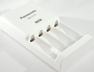
This is a easy to use and slow charger from Panasonic, it has a build-in USB charger.
I did not get the original box with the charger.
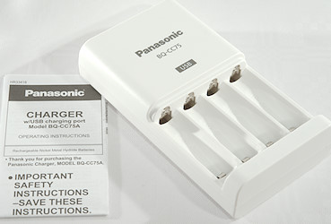
The pack included the charger, mains cable and instruction/safety sheet in a lot of languages.
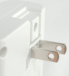
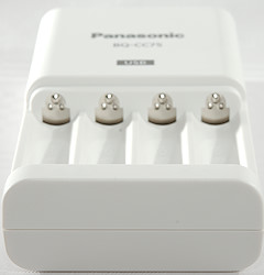
The charger is powered directly from mains and do not have other power options.
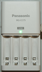
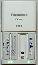
The only user interface is a couple of leds, one for USB and four for charging.
All leds are green and the leds for batteries are green when charging, flash when there is an error and turned off at all other times.
The USB led is green when there is a plug in the USB connector.
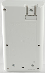
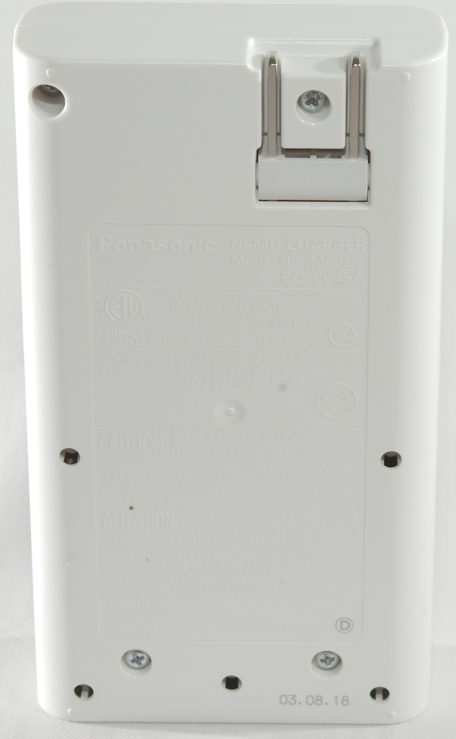
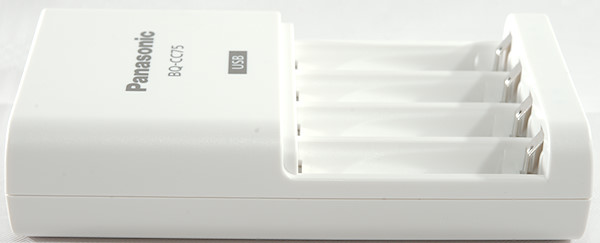
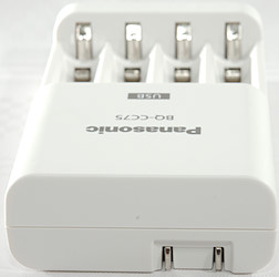
There are some specifications and warnings on the back of the charger, but they are very hard to read. It says BQ-CC75A here.
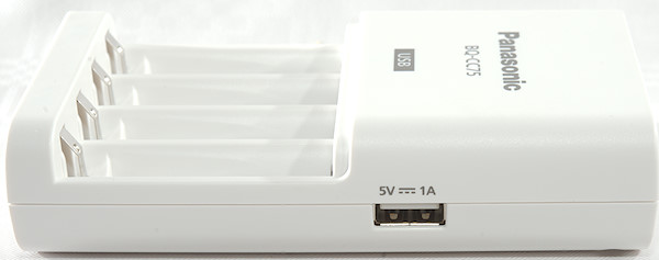
The usb output is clearly marked with voltage and current.
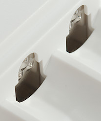
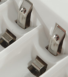
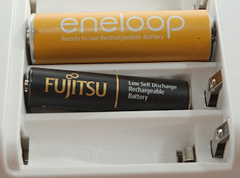
The charger has the typically two level slots used for AA and AAA batteries.
Measurements charger
- When not powered it will discharge the battery with below 0.1mA
- The charger will not charge batteries below about 0.6V
- If the charger detect an error the green led will flash
- The charger use peak currents up to 1.2A
- The charger will timeshare one charge circuit between all four slots.
- Charge will restart charging after power loss, or battery insertion.
- Power consumption when idle is 0.07 Watt
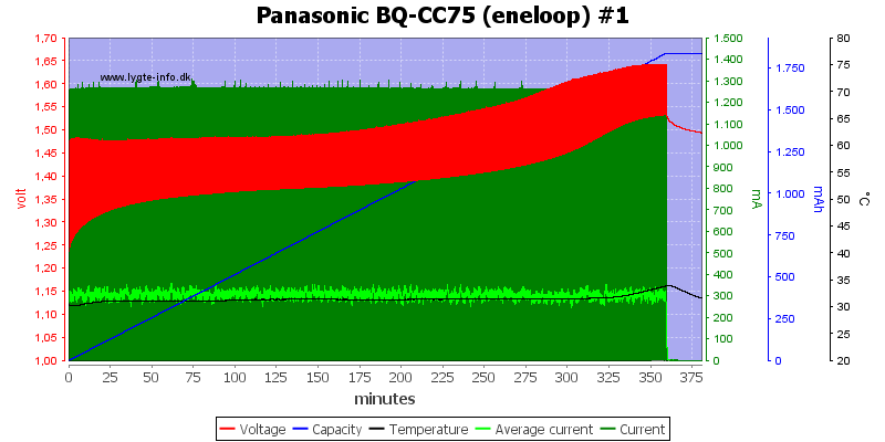
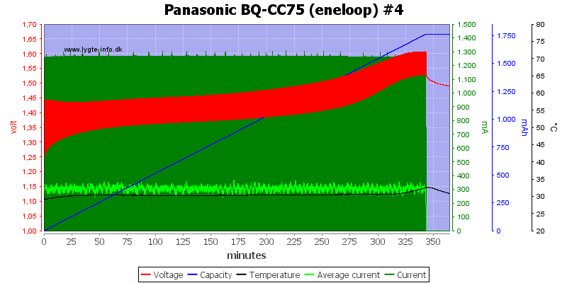
The termination looks like a 0dv/dt or slope detection and is very fast. The actual charge current is 300mA. There is no top-off or trickle charger, this is fine for this type of charge algorithm.
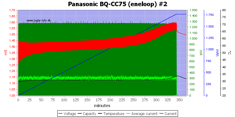

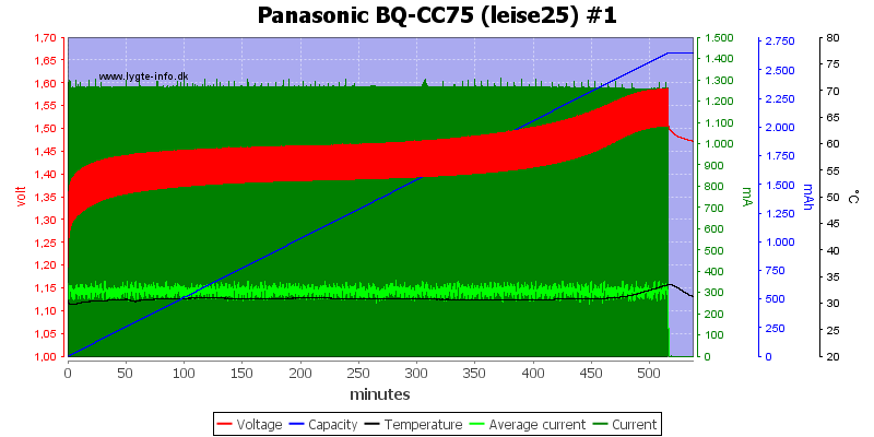
The other slots are similar.
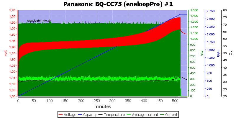
The two high capacity cells are also handled nicely.
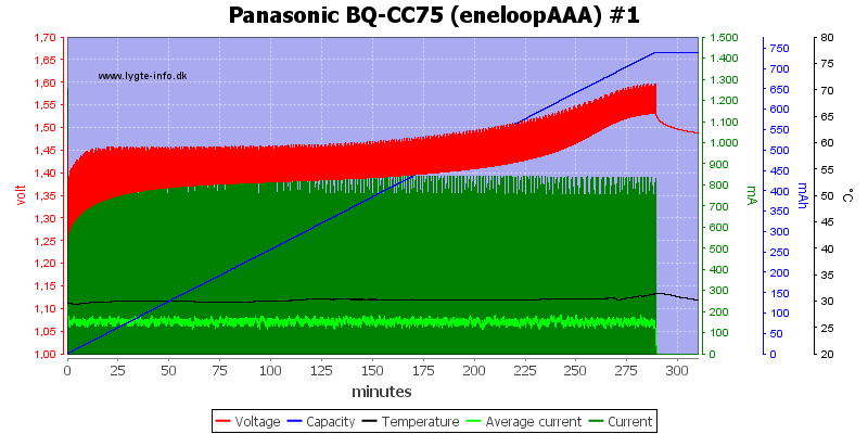
With AAA batteries the current is reduced to about 150mA.
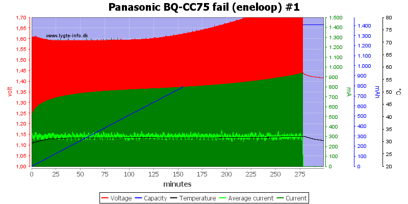
The charger failed a few time, probably because the batteries are old with rather high internal resistance (The red line is very thick).
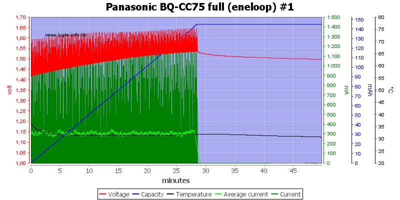
The charger is not exactly fast in detecting a full battery, here it took about 28 minutes.
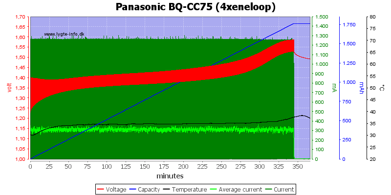
The current is the same with four batteries in the charger.
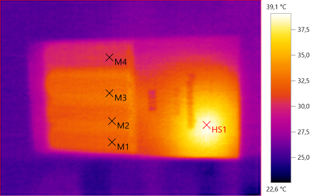
M1: 32.1°C, M2: 32.7°C, M3: 32.8°C, M4: 30.4°C, HS1: 39.1°C
The low charge current means the charger and batteries are fairly cool.
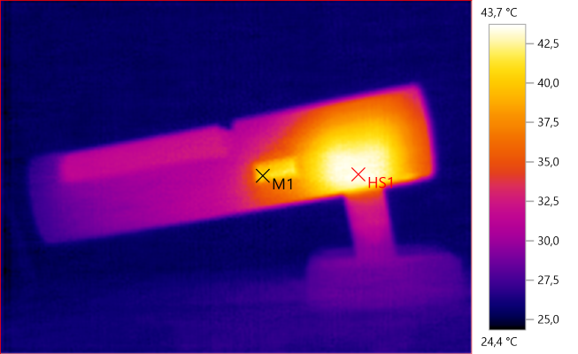
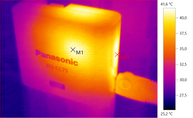
M1: 40.9°C, HS1: 43.7°C
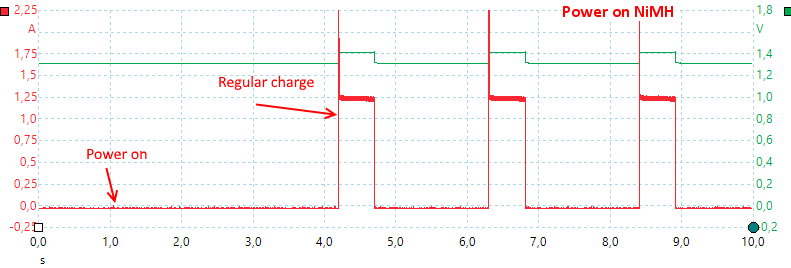
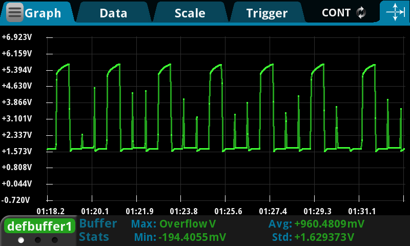
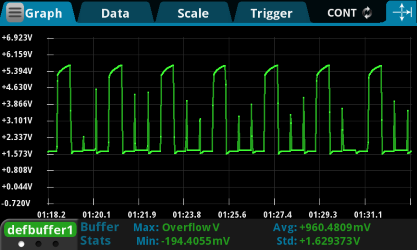
The charger needs a few seconds to start and uses pulses. The current regulation is a bit slow and it starts each pulse with a short high current pulse, I do not expect it will do any damage to the batteries.
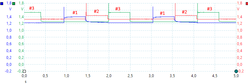
With 3 batteries in the charger the time sharing is easy to see.
USB output
- Power consumption when idle is 0.07 Watt
- USB output is coded as USB charger (DCP)
- USB connector will detect a connected cable physically and turn on the USB indicator.
- When a USB connector is plugged in the battery charger part is disabled.
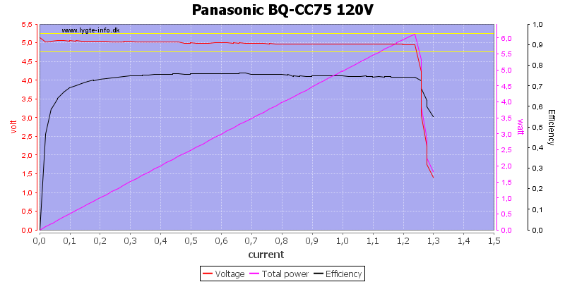
The USB output is rated for 1A and can deliver 1.25A, this is fine.
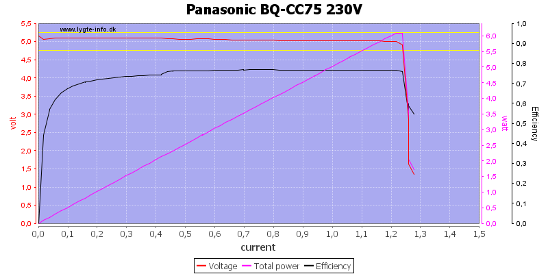
Using 230V do not change it.
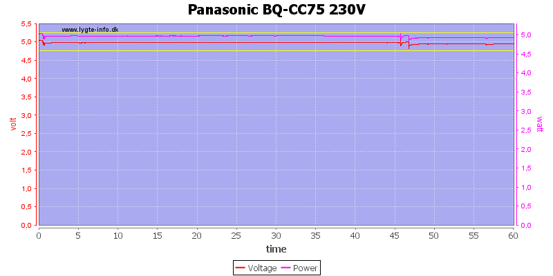
No problems running one hour at 5V 1A, the marks in the curve is because the US mains to EU mains adapter is a bit unstable when I turn the charger around for the IR photos.
The temperature photos below are taken between 30 minutes and 60 minutes into the one hour test.
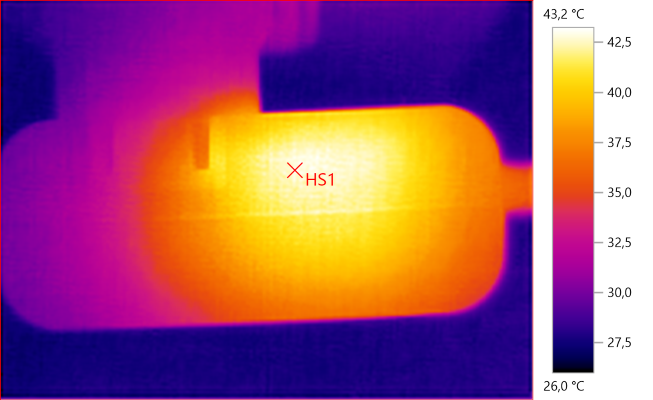
HS1: 43.2°C
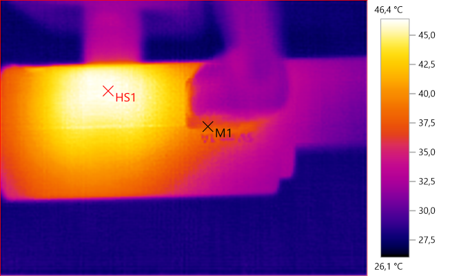
M1: 37.7°C, HS1: 46.4°C
M1: 41.1°C, HS1: 41.6°C
There is not much heat with USB.
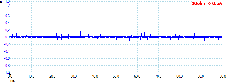
Noise is 14mV rms and 459mVpp
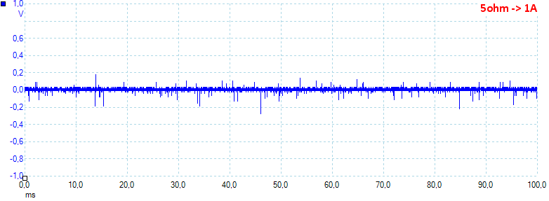
Noise is 21mV rms and 578mVpp.
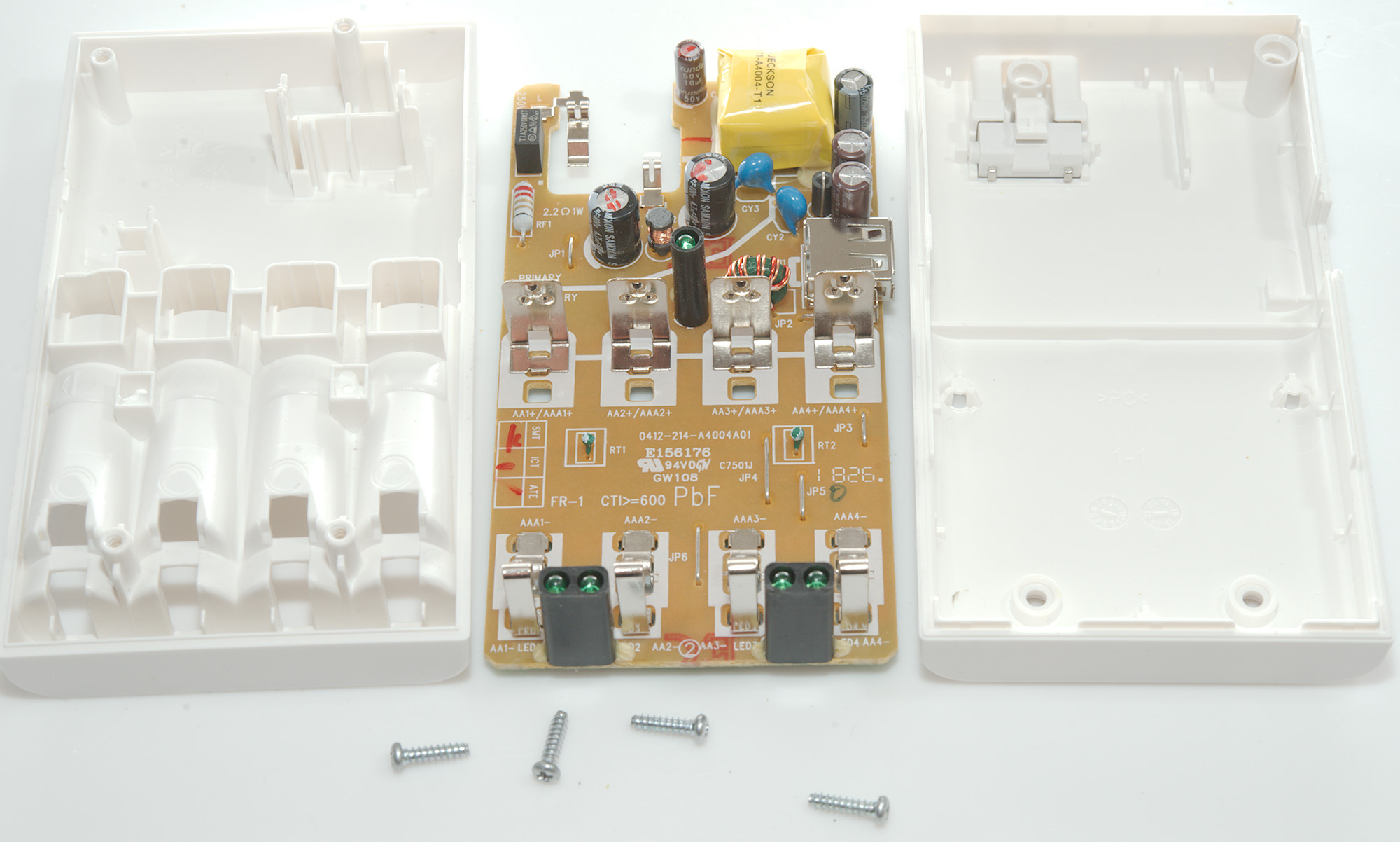
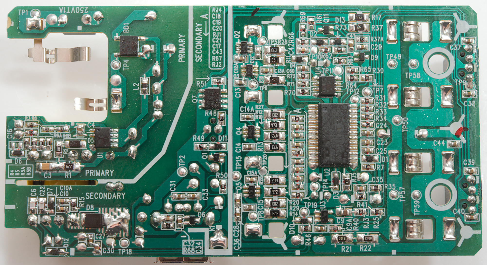
Tear down
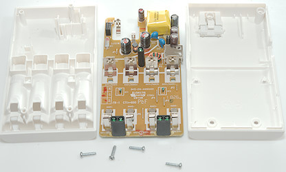
There was a few details I was curious about with the charger and I decided to open it. It was easy, there was only four screws.
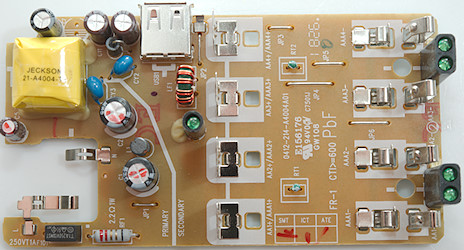
On this side is the mains fuse and a fusible resistor (RF1), two smoothing capacitors (C1 & C2) with a inductor between (L1). There is two safety capacitors in series. There is a common mode inductor (LF1) on the low volt side, it is used for the USB output.

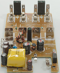

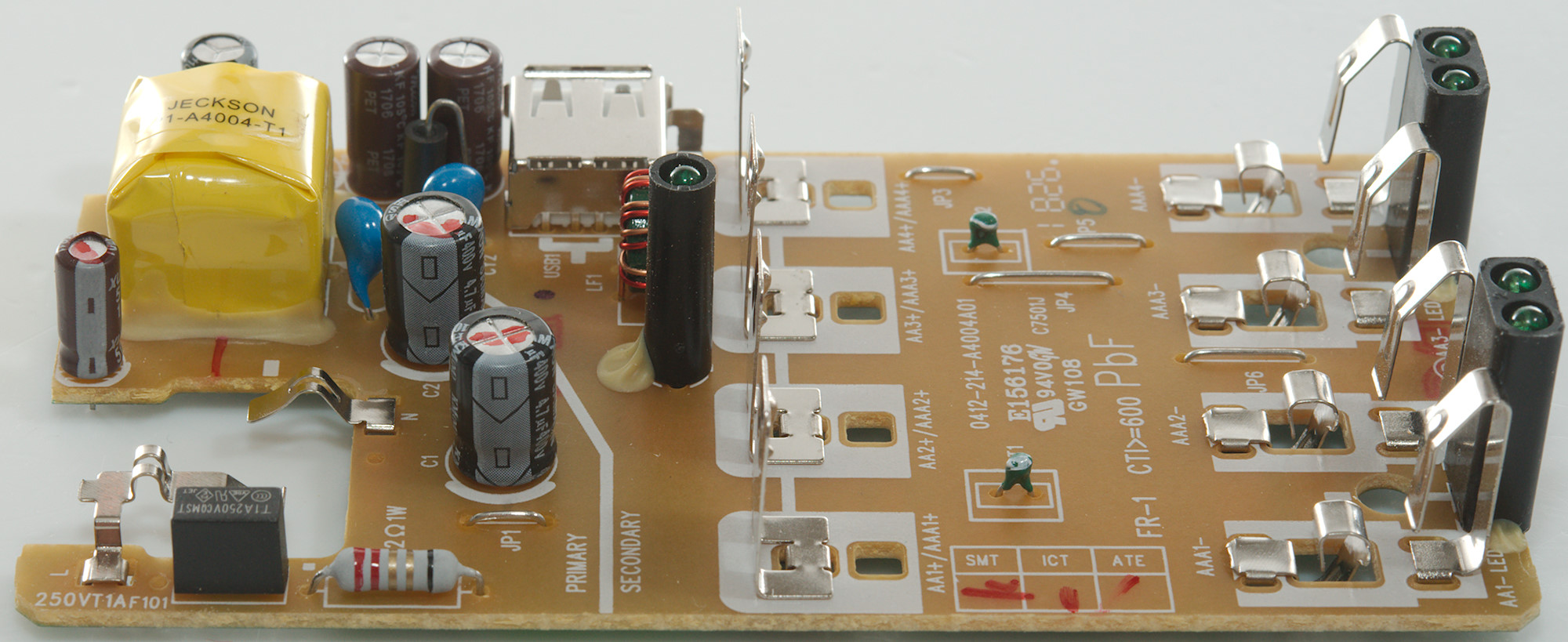
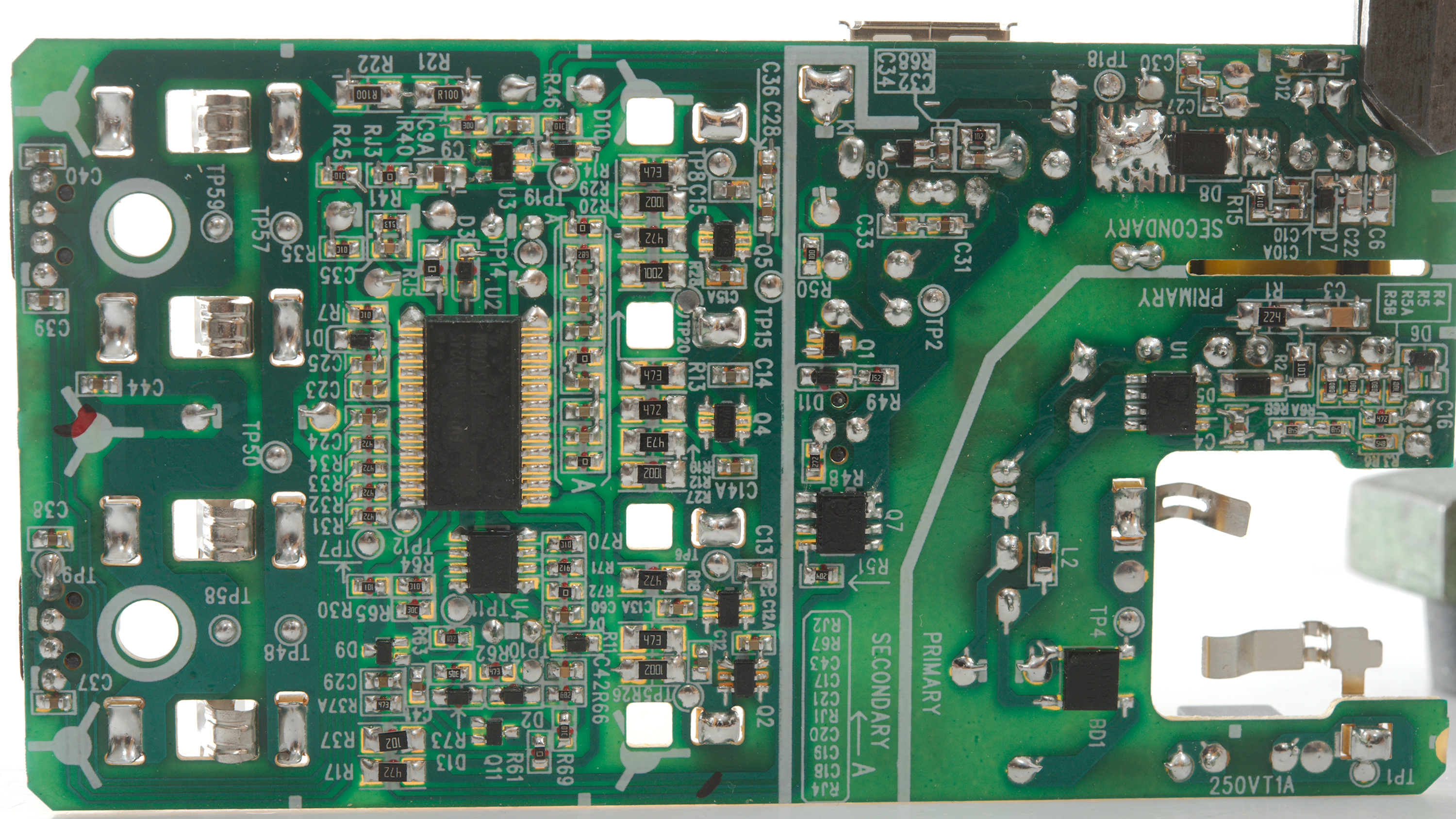
On this side at the mains input is a bridge rectifier (BD1) and a switcher (U1). On the low volt side it there is two low voltage output, one with a high current diode (D8) and one with a low current diode (D12). The high current is for charging and USB output, the low voltage is considerable higher voltage (10-17V).
Power to the charging circuit is controlled by transistor (Q7) and a dual transistor for each slot (Q2, Q3, Q4, Q5)
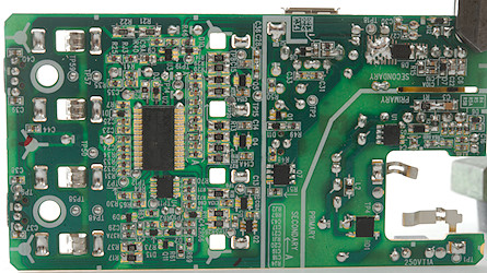
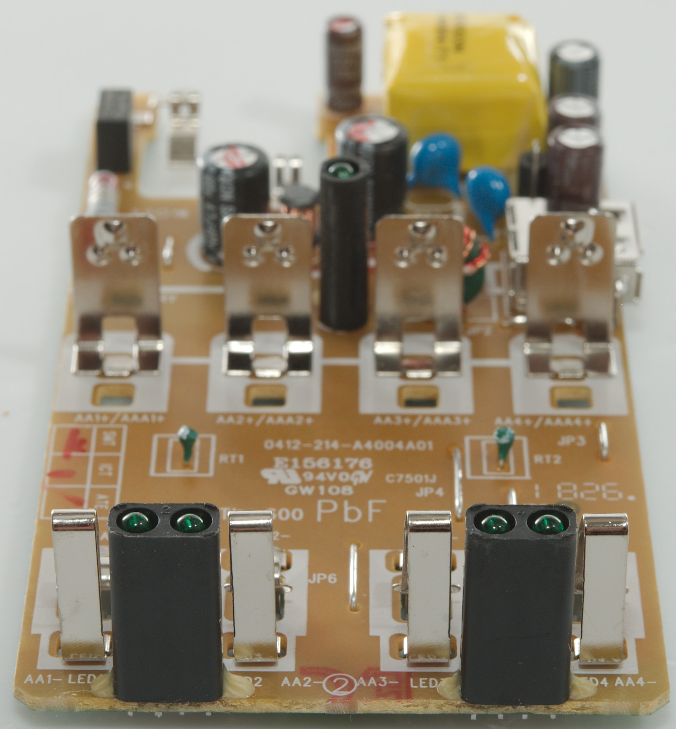
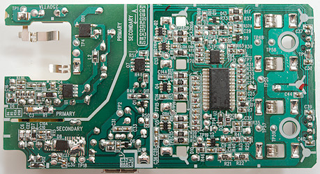
Circuit board with backlight.
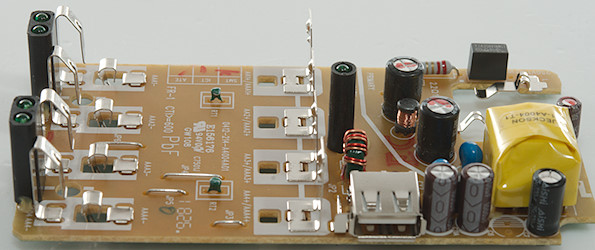
The high current output is up to 5.6V, but will drop in voltage when charging, above I have 3 batteries in the charger. When using the USB output it is regulated to 5.2V. At the USB connector there is a transistor (Q6) to detect connection between USB GND terminal and the metal of the connector.

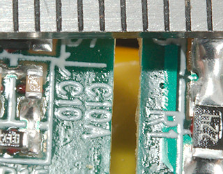
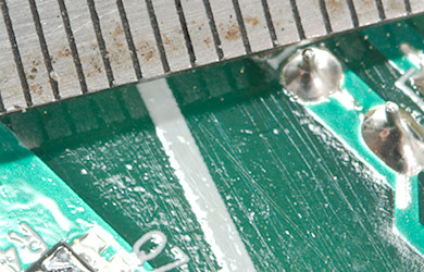
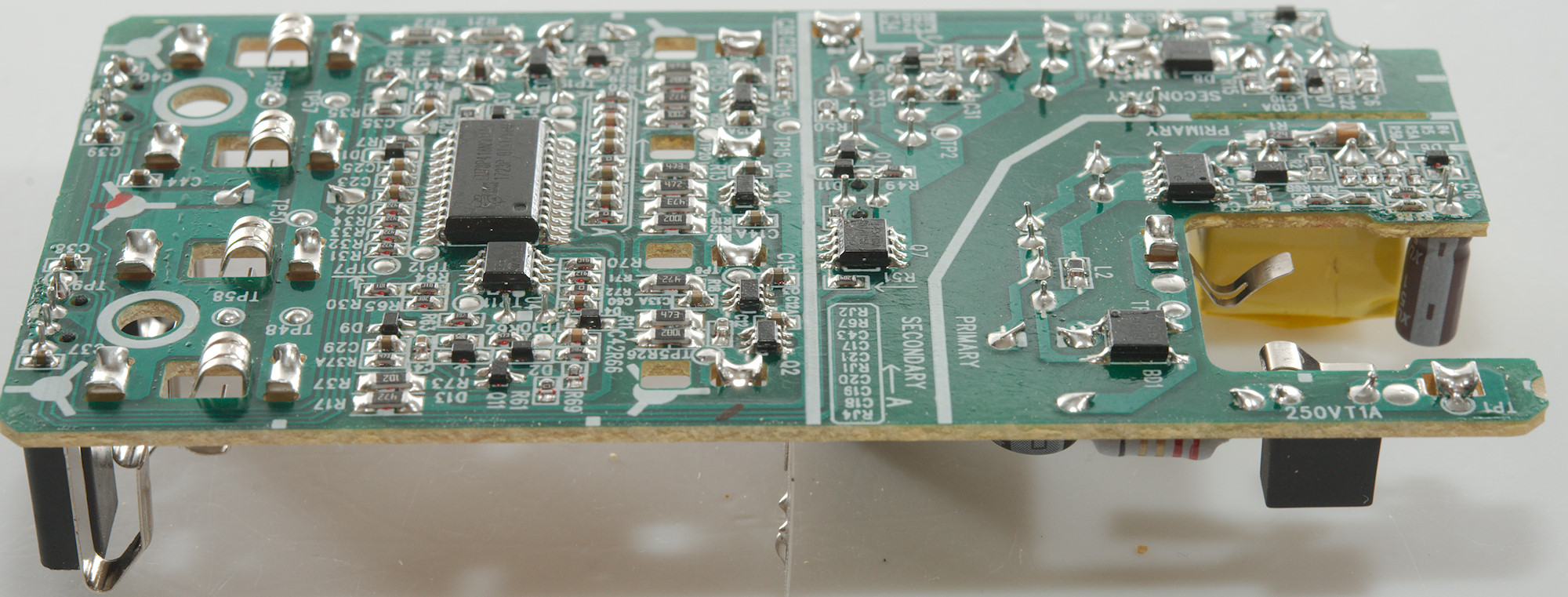
The distance between mains and low volt side is very good.
Testing with 2500 volt and 5000 volt between mains and low volt side, did not show any safety problems with the charger.
Conclusion
The charger is a very good NiMH charger, but slow. It will charge batteries exactly full, not anything more.
USB output also works fine, but 1A is not that much current.
The total output power is rather limited, either it can charge batteries or it can charge a USB device, but not both at the same time.
Notes
The charger was supplied by a reader for review.
Here is an explanation on how I did the above charge curves: How do I test a charger
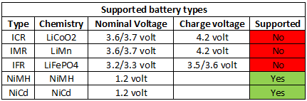
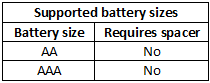
Charger selection table