YZXStudio USB meter ZY1271
Official specifications:
- Input voltage: DC 3.5V-24V
- Input current: +- 3A
- Voltage resolution: 0.0001V (0.1mV)
- Current resolution: 0.0001A
- Cumulative capacity: 0-99999Ah; 0-99999Wh
- Capacity resolution: 0.0001Ah; 0.0001Wh
- Accuracy: Voltage 0.1%+2d; Current 0.2%+2d; Ah capacity 0.5%; Wh capacity 0.5%
- Display: 1.3" 128x104 pixel Colour TFT
- Update rate: Every 0.36s
- Idle current consumption: ~8mA / 6mA (with display dimmed / off)
- Current shunt resistance: 10mOhm
- Overall circuit resistive loss: ~42mOhm (including contact resistance on USB connectors)
- Memory: FRAM, good for 10 billion write cycles
- Memory operation mode: write on every update in cumulative capacity + load balancing technique
I got it from ebay dealer diyelecmall108.
YZXStudio makes a series of usb meters with nearly identical specifications, there is also sometimes software update with improvements. It is possible to install update, but it requires special tools and access to the updated software.
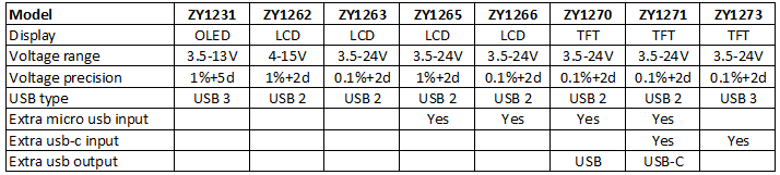
This table compares some of the YZXStudio usb meters, I only include parameters where there is difference.
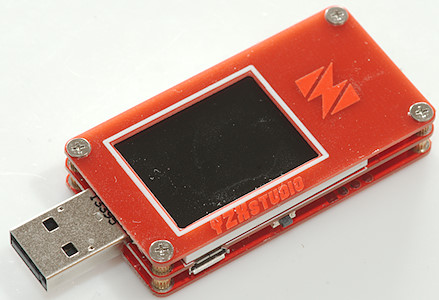
How does it look
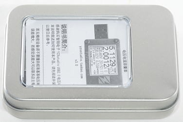
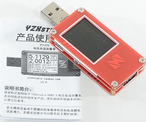
I got it in a small metal box with a Chinese (I assume) manual, because the user interface is basically the same as all other YZXStudio meters I did not have any problems using it.
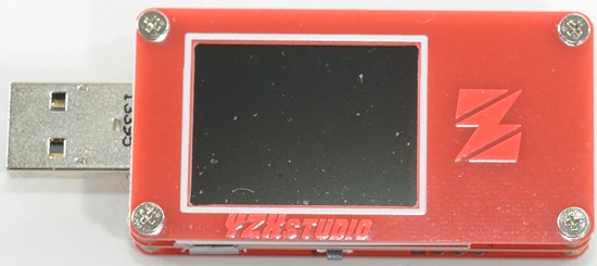
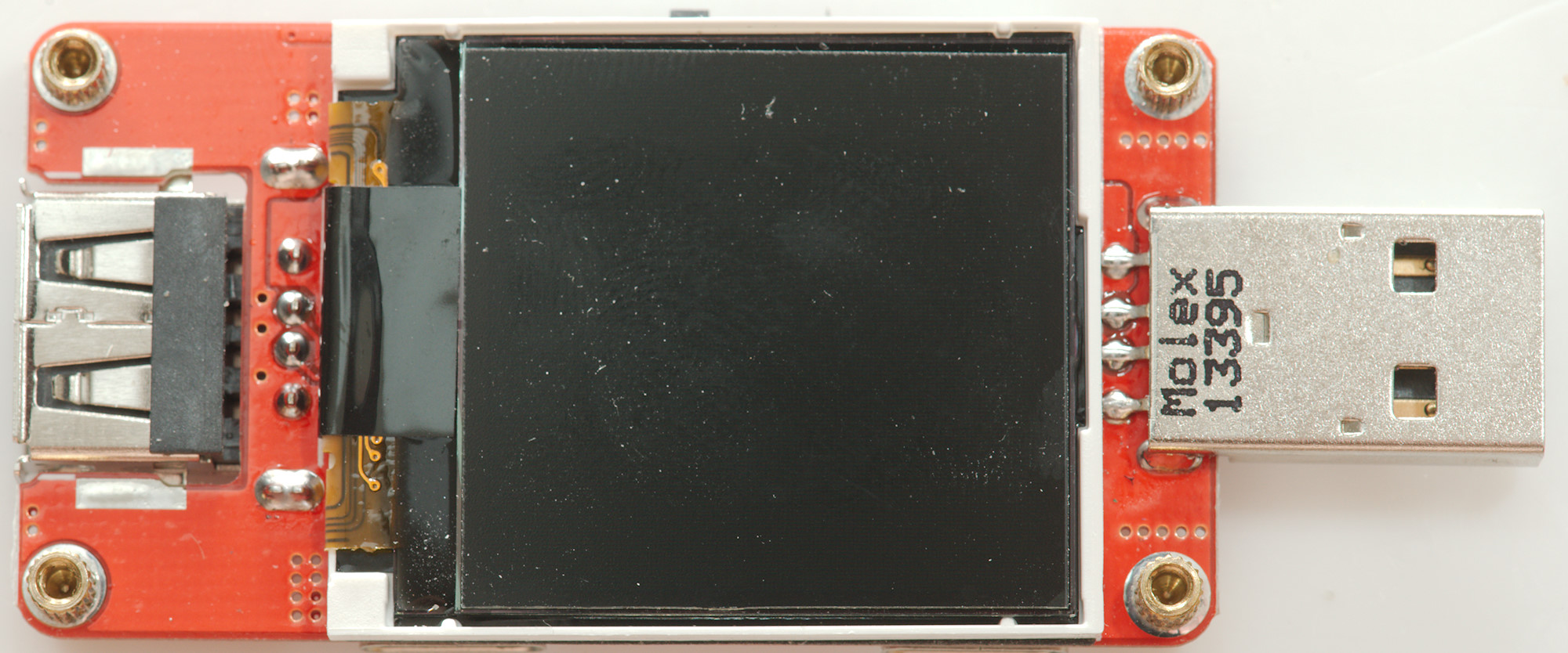
The display is a color screen.
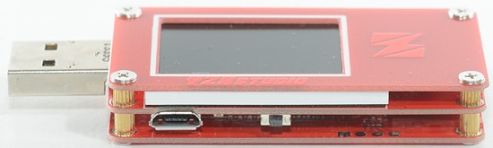
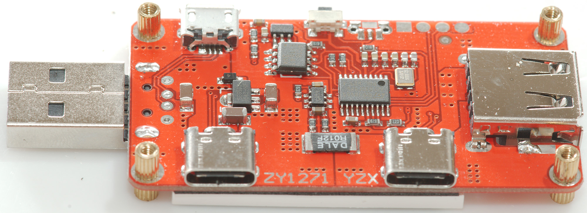
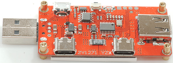
On this side is the button and a micro usb input connector.
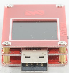
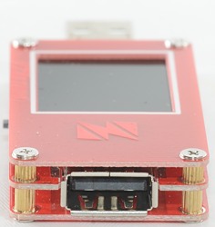
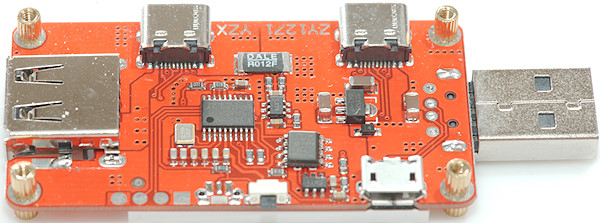
The usb input and usb output connectors.
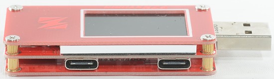
The usb-c connectors, one input and one output. These are directly connected, there is no chip or resistors inside this meter.
usb-c, usb and mini usb data pins are connected, this makes it possible to use it as a converter between the connector types.
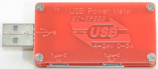
Specifications are marked on the back, but as usual the type is not marked.
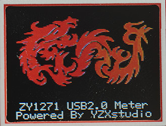
Welcome screen, it is shown when power is applied (it can be disabled).
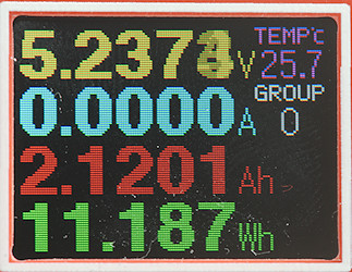
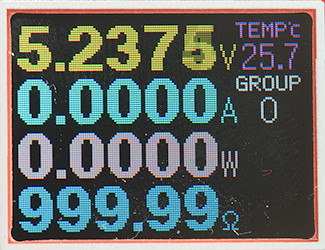
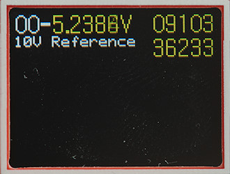
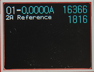
The first screen, it shows V, A, Ah and Wh, the "0" is selected memory bank.
It do also have space for the MCU temperature.
Next screen shows W and ohm, instead of Ah and Wh.
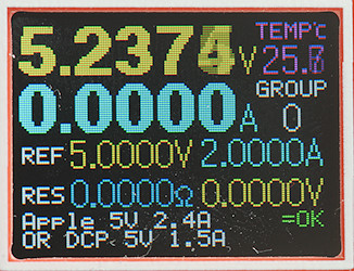
This screen is used to calculate cable resistance, to use it a constant current load is required.
First do a measure without the cable, hold down the button to set the reference. Then add the cable between the usb power source and the usb meter. The display will show the resistance.
It also includes the usb coding, this can sometimes be ambiguous and it will then show more than one coding.
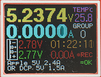
This screen shows usb coding and data pin voltage. It also shows the trickle current threshold and time the current has been above that threshold, only current above this value is summed (Value is configurable). The temperature is the internal MCU temperature.
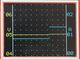
A chart of current and voltage, sample rate can be configured. Scale will move depending on voltage and current, it will not change.
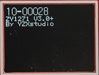
Holding the button down during power on makes it possible to enter the configuration. The first screen in the configuration will show the software version.
It is possible to calibrate the meter.
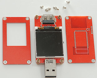
As usual it is easy to open, just remove the 8 screws.

On this side there is only the display.
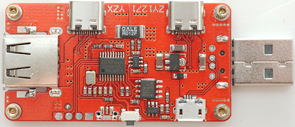
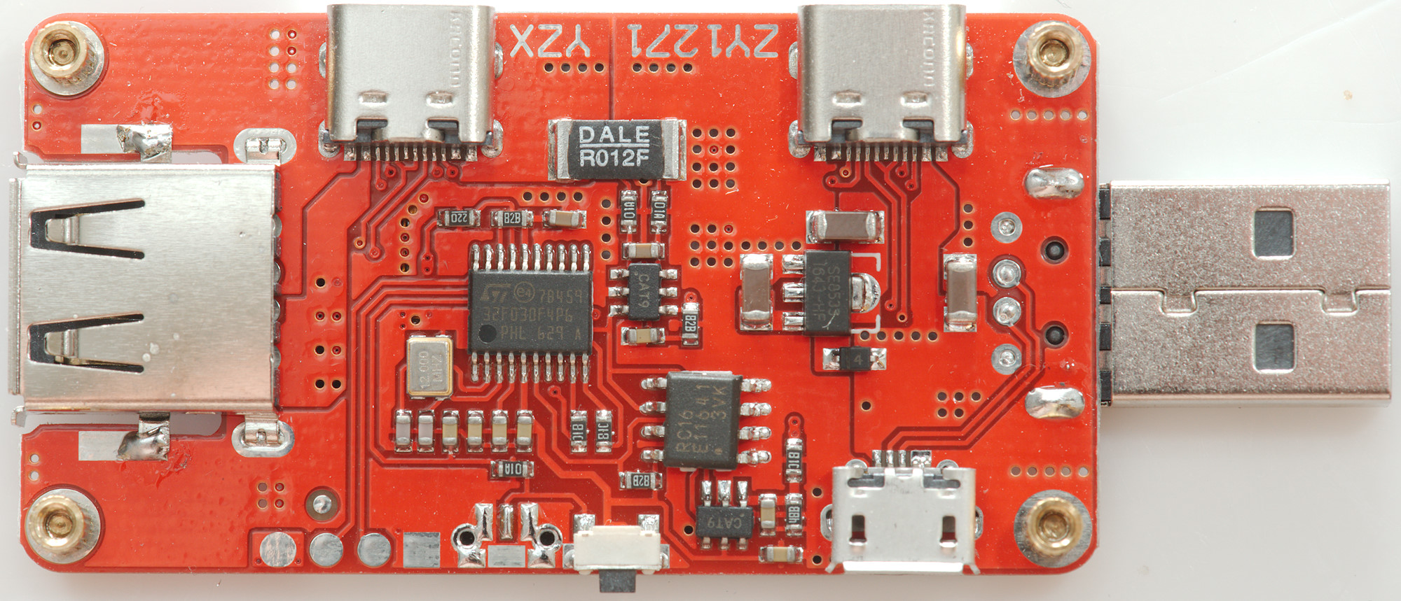
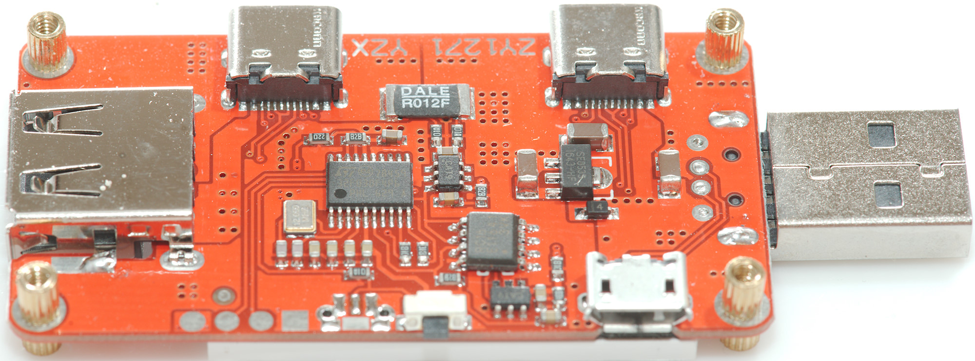
The construction is fairly simple: There is a microcontroller (ST 32F030F4P6), two ADC (Marked CAT9), a FRAM (Marked RC16 / E11641 / 3VVK) and a 3.3 V regulator (SE8533).
The current sense resistor is 12mOhm, the rest of resistance is from tracks on the circuit board and connection resistance.
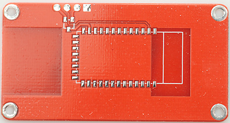
On the bottom circuit board there is space for a Bluetooth module.
Measurements
Measurements are done on usb port.
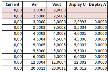
The voltage display is fairly precise with no current flowing (Both voltage and current can be calibrated by the user, I have not changed the calibration).
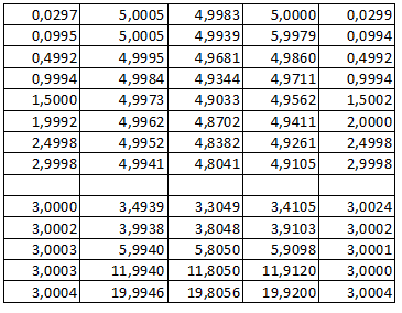
The current display is also fairly precise and will not change with voltage.
- The tested usb meter uses software V3.00
- The voltage readout is within 0.012 volt (Around 5V <0.0003V) when unloaded.
- When loaded the voltage will be closest to the usb input voltage.
- Current is within 0.0002A.
- Remembers Wh and Ah when power is off
- The usb meter uses about 12.8mA current with normal brightness, 8 when dim.
- The internal resistance is about 0.06ohm (This includes both connectors).
- USB data works fine.
- There is no IC or resistor on USB-C
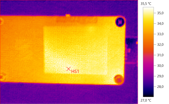
HS1: 35,5°C
The above IR photo was taken after 30minutes with 3A, during that time the voltage and current readout changed less than 0.02%
I have played a bit with the cable resistance function, it uses ohms law and is as precise as possible. How precise that is depends on how stable the voltage is, how stable the current is and how stable the connection resistance is. With my lap grade equipment I can get within a few mOhm (1/1000 ohm), for that test I did not even change usb connection (That alone can be 30mOhm). With more normal equipment I would not expect better than 30-100mOhm. Even with that tolerance it is very useful to get rid of bad (High resistance) usb cables.
Conclusion
This is a very precise usb meter (I am impressed with the calibration) with many interesting functions. With both good precision and external logging in can be used for testing usb equipment.
The larger and always on display makes it easier to read, it is possible to adjust or display the timeout before it goes on low brightness.
The resistance in this device is very low.
The usb-c is fairly simple without any resistors or IC's, this means it will not work stand-alone with all devices. I do miss some voltage/resistor readout for the CC pins.
Notes
For this USB meter I used precise equipment (Keithley: DMM7510, 2280S, Keysight: 34470A).
How do I make the test